FS DCP920 Series User manual

DCP920 SERIES USER MANUAL
Copyright © 2009-2023 FS.COM All Rights Reserved.

DCP920 SERIES USER MANUAL
1. Summary.............................................................................................................................................................................................................................1
2. Equipment Chassis Introduction.................................................................................................................................................................................2
2.1 DCP920 Series Equipment........................................................................................................................................................................................2
3.Equipment Description................................................................................................................................................................................................... 3
3.1 Description of the Front Side of the Chassis.......................................................................................................................................................3
3.2 Description of the Rear Side of the Chassis........................................................................................................................................................ 4
4.WEB Introduction.............................................................................................................................................................................................................. 6
4.1 Login Interface............................................................................................................................................................................................................. 6
4.2 Operation Interface.................................................................................................................................................................................................... 6
4.3 Functional Division..................................................................................................................................................................................................... 8

DCP920 SERIES USER MANUAL
1
1. Summary
DCP920 series is an integrated WDM transmission platform, which meets the application scenario of 4x 100G/8x 100G
business 0~80KM point-to-point transmission without repeater, adopts PAM4 DWDM transmission technology, and has
built-in VOA, TDCM, and DCM to support line-side optical power, automatic adjustment of dispersion. Out-of-band OSC
interface can manage multiple devices, stack and expand capacity; the appearance conforms to the switch form, suitable for
customers in the data industry, reduces the difficulty of system fiber connection, and facilitates service activation and daily
maintenance.

DCP920 SERIES USER MANUAL
2
2. Equipment Chassis Introduction
2.1 DCP920 Series Equipment
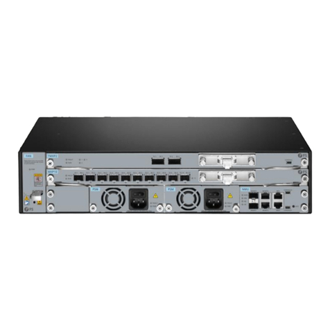
Figure 2-1 DCP920 series equipment diagram
Table 2-1 DCP920 series device features
Feature Description
Slot capacity
DCP920-D04P: 4 module service slots, 4 LC/UPC transmission slots, 2 1+1 backup power supply
slots, and 3 1+1 fan slots.
DCP920-D08P: 8 module service slots, 4 LC/UPC transmission slots, 2 1+1 backup power supply
slots, and 3 1+1 fan slots.
Power supply
Support 1+1 backup AC power supply
Input range:
AC Input:100~240V
Dimensions (HxWxD)486mm(W)x 540mm(D)x 44.5mm(H)(Without hanging ears and front and rear pull rings)
Working environment
Working temperature:-40℃~45℃
Storage temperature:-40℃~80℃
Relative humidity:5%~95%,no condensation.

DCP920 SERIES USER MANUAL
3
3.Equipment Description
3.1 Description of the Front Side of the Chassis
Figure 3-1 DCP920 series front side device diagram
Slot assignment
NMU
1
Optical interface
2
Line interface
3
Figure 3-2 slot allocation of DCP920 series
Function
The functions on the front side of the device are as follows
The main control network port provides the main control WEB monitoring function, and the device optical port provides
the communication function between devices
Provide 4x 100G/8x 100G QSFP28 type interface, which can realize 4x 100G/8x 100G service transmission
Provide transmission service cable access, monitoring optical cable access, expansion interface access
Shrapnel switch
To disassemble and replace the main control card, you need to pull the pull ring, lift up the shrapnel with your fingers, and
pull out the main control card.
Indicator light
Table 3-1 DCP920 series knowledge light description
Indicator type Situation LED status
Running status/Connection statuPanel indicator light s Steady green light
Closed state/Not connected state Extinguished
Interface indicator Unconnected state Both left and right
extinguished

DCP920 SERIES USER MANUAL
4
Link state The green light on the left is always
on, and the yellow light on the right
flashes regularly
Port Table 3-2 DCP920 series interface description
Port name Port type Use
Main control card electrical
port RJ45 Link PC for communication or electrical port
communication between devices
Main control card optical port SFP Link other devices for traffic or supply power to
optical modules
Service optical module port QSFP28 Link service optical module transmits information
data
Service optical transmission
port LC/UPC Link transmission business optical fiber
transmission information data
3.2 Description of the Rear Side of the Chassis
Figure 3-3 DCP920 series rear device diagram
Slot allocation
AC POWER
4
FAN
5
FAN
6
FAN
7
AC POWER
8
Figure 3-4 DCP920 series rear panel function allocation
Function
The functions on the front side of the device are as follows
Equipment power supply
Auxiliary chassis heat dissipation

DCP920 SERIES USER MANUAL
5
Switches
Table 3-3 DCP920 series switch description
Switch type Situation Switch status Method of use
Shrapnel switch Replacement,
removal
Pull the ring, lift up the shrapnel
with your fingers, and pull out the
main control card
Switch
Open state Red switch no light Power switch online dial
Closed state Red switch lights red Power switch network dial down
Port
Table 3-4 DCP920 series switch description
Interface type Situation Switch status Method of use
Shrapnel switch Replacement,
removal
Pull the ring, lift up the shrapnel with
your fingers, and pull out the main
control card
Switch
Open state Red switch no light Turn the power switch up
Closed state Red switch lights red Turn the power switch down

DCP920 SERIES USER MANUAL
6
4.WEB Introduction
The login bar is composed of account number, password, and login options. There is alanguage selection bar at the bottom right,
and the language can be
4.1 Login Interface
changed.
The operation bar is divided into user management panel, function panel, display\setting panel, confirmation
4.2 Operation Interface
panel.
User management panel
Function panel
The function panel consists of system resource, system configuration, alarm record, and device diagnosis. Among them, the system
configuration is divided into power configuration and dispersion configuration; dispersion configuration has manual adjustment and
automatic adjustment.

DCP920 SERIES USER MANUAL
7
Show\Settings panel
It can display the actual device front panel, device information, and setting items.
Confirmation panel
Every time an option is set, a confirmation panel will pop up, click the green confirmation button to implement, and the red cancel
button to cancel.

DCP920 SERIES USER MANUAL
8
System resource
4.3 Functional Division
System resource display items consist of device information and DCP920 series.
Equipment information mainly operates the main functions, such as internal clock, resource allocation, fan control, IP
management, and master control card information display.

DCP920 SERIES USER MANUAL
9
DCP920 series Mainly for data display, display the optical module electrolight, temperature, wavelength, etc., but also display
the equipment electrolight, dispersion compensation value of the main data.
System configuration
It consists of the power configuration and the dispersion configuration, both of which are the setting panel.
Power can be configured manually and automatically, control the optical power of the sending and receiving orientation and
can set the threshold for power alarm.

DCP920 SERIES USER MANUAL
10
The automatic adjustment of dispersion needs to set the length of the optical cable in advance, the length is the length of the
optical cable measured in advance, the fixed dispersion is usually 40 by default, the default value of the factory dispersion range
Manual adjustment needs to know the dispersion adjustment value and input, the frequency interval changes according to
is 800, the default value of the factory dispersion slot is 3, and the remote IP is the IP of the peer device Master control IP
address, after setting, use the adjustment enable to adjust.
the transmission frequency, the normal situation is 100.

DCP920 SERIES USER MANUAL
11
Warning records
By uploading the upgrade file, click Upgrade to upgrade the
Equipment
It consists of event type, date and time, search button, download button, delete button, and data display interface.
Select the event type you want to know, select the time interval you want to know, and click the search button to query the
relevant search results.
upgrade
software.
This manual suits for next models
2
Table of contents
Other FS Network Hardware manuals
Popular Network Hardware manuals by other brands

Extreme Networks
Extreme Networks Universal Compute Platform Appliance 4120C installation guide

D-Link
D-Link MYDLINK DNR-322L Technical specifications

TechnoSpark Systems
TechnoSpark Systems NMEA 2000 Wifi Replicator user manual

binardat
binardat SIG1 user manual

Avocent
Avocent Cyclades ACS 6000 Installation & administrators guide

Bdcom
Bdcom GP3600-08 GPON installation manual