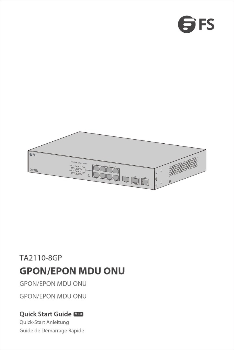
FS T8550-32C User manual

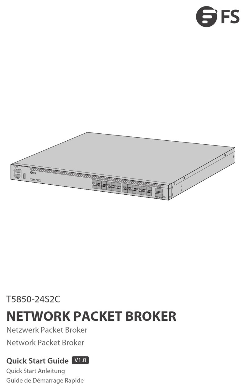
NETWORK PACKET BROKER
NETZWERK-PACKET-BROKER
NETWORK PACKET BROKER
V1.0
Quick Start Guide
Quick Start-Anleitung
Guide de Démarrage Rapide
T8550-32C
25 26 27 28 29 30 31 32
17 18 19 20 21 22 23 24
910 11 12 13 14 15 16
1 2 3 4 5 6 7 8
T8550-32C
ID
MGT
SYS
CON
ETH
100G 40G/100G 100G
Breakout
1 2 3 4

Introduction
T8550-32C
Thank you for choosing T8550-32C Network Packet Broker. This guide is designed to familiarize you
with the layout of the switch and describes how to deploy the switch in your network.
1
EN
Accessories
Power Cord x2 Cat5e Cable x1
Console Cable x1
Grounding Cable x1 Rubber Pad x4
M4 Screw x10
Front Mounting Bracket x2 Slide Rail x2Rear Mounting Bracket x2
T8550-32C
IDMGTSYS
CON
ETH
100G 40G/100G 100G
Breakout
1 2 3 4
12 34 56 78 910 11 12 13 14 15 16 17 18 19 20 21 22 23 24 25 26 27 28 29 30 31 32

Hardware Overview
Front Panel Ports
Front Panel LEDs
Port Description
USB
CON
MGMT
A USB management port.
An RJ45 console port for serial management.
An Ethernet management port.
QSFP28 QSFP28 ports for 40/100G transceivers.
2
EN
T8550-32C
IDMGTSYS
CON
ETH
100G 40G/100G 100G
Breakout 1 2 3 4
1 2 3 4 5 6 7 8 9 10 11 12 13 14 15 16 17 18 19 20 21 22 23 24 25 26 27 28 29 30 31 32
QSFP28
CON
USB
MGMT
T8550-32C
IDMGTSYS
CON
ETH
100G 40G/100G 100G
Breakout 1 2 3 4
1 2 3 4 5 6 7 8 9 10 11 12 13 14 15 16 17 18 19 20 21 22 23 24 25 26 27 28 29 30 31 32
QSFP28
Breakout
IDSYS MGMT

Back Panel
Installation Requirements
Do not operate it in an area that exceeds an ambient temperature of 45°C.
The installation site should be well ventilated.
Be sure that the Network Packet Broker is level and stable to avoid any hazardous conditions.
Do not install the equipment in a dusty environment.
The installation site must be free from leaking or dripping water, heavy dew, and humidity.
3
EN
ID
ID indication function enable.
Blue
On
Off
On
On
On
On
Blinking
Blinking
On
Off
Green
Green
ID indication function disable.
The system is normal running.
The system occur alarm or error.
No power or System is not run or abnormality.
SYS Amber
Off
Port not link.Off
Port link.
Port not link.
LED State Description
QSFP28
Breakout
Loop Blinking
Off
One or more 100G/40G ports are breakout.
None of the 100G/40G port is breakout.
Green
Amber
100G/40G port link.
10G/1G port link.
10G/1G packets receiving or transmitting.
100G/40G packets receiving or transmitting.
MGMT
4 Fans
PS1PS2
Power
Grounding Point
Power
25 26 27 28
1227 28 25 26 27 28
T8550-32C
IDMGTSYS
CON
ETH
100G
910 11 12
1 2 3 4 5 6 7 8
T8550-32C
IDMGTSYS
CON
ETH
100G

Mounting the Network Packet Broker
Rack Mounting
1. Install the front mounting brackets and the slide rails on the network packet broker.
2. Fix the rear mounting brackets onto the rack.
3. Push it gently onto the rack along the slide rail, and fix the other end of front mounting brackets
upon the front hold strip of rack using screw and its matching nut.
4
EN
25 26 27 28 25 26 27 28
25 26 27 28 25 26 27 28
28 25 26 27 28
40G/100G 100G
Breakout
1 2 3 4
25 26 27 28 29 30 31 32
17 18 19 20 21 22 23 24
12 13 14 15 16
40G/100G 100G
Breakout
1 2 3 4
25 26 27 28
25 26 27 28 25 26 27 28
25 26 27 28 25 26 27 28
T8550-32C
IDMGTSYS
CON
ETH
100G 40G/100G
17 18 19 20
910 11 12 13 14 15 16
1 2 3 4 5 6 7 8
T8550-32C
IDMGTSYS
CON
ETH
100G 40G/100G

1. Connect one end of the grounding cable to a proper earth ground, such as the rack in which the
network packet broker is mounted.
2. Secure the grounding lug to the grounding point on the back panel of the network packet broker
with the washers and screws.
Grounding the Network Packet Broker
5
EN
CAUTION: The earth connection cannot be removed unless all connections are
disconnected.
PS2
PS2
25 26 27 28 25 26 27
T8550-32C
IDMGT
SYS
CON
ETH
100G
1 2 3 4 5 6 7
T8550-32C
IDMGTSYS
CON
ETH
100G
25 26 27 28 25 26 27 28
28 25 26 27 28
100G
Breakout
1 2 3 4
25 26 27 28 29 30 31 32
20 21 22 23 24
100G
Breakout
1 2 3 4

1. Plug the AC power cord into the power port on the back panel of the Network Packet Broker.
2. Connect the other end of the power cord to an AC power source.
Connecting the Power
6
EN
WARNING: Do not install power cords while the power is on.
1. Plug the compatible QSFP28 transceiver into the QSFP28 port.
2. Connect a fiber optic cable to the fiber transceivers. Then connect the other end of the cable to
other fiber devices.
Connecting the QSFP28 Ports
PS1
PS1
25 26 27 28 25 26 27 28
25 26 27 28 25 26 27 28
25 26 27 28 25 26 27 28
27 28
40G/100G 100G
Breakout
1 2 3 4
25 26 27 28 29 30 31 32
17 18 19 20 21 22 23 24
910 11 12 13 14 15 16
8
40G/100G 100G
Breakout
1 2 3 4

1. Connect the DB9 female connector of the console cable to RS-232 serial port on the computer.
2. Insert the RJ45 connector into the RJ45 console port on the front of the network packet broker.
Connecting the Console Port
1. Connect one end of a standard RJ45 Ethernet cable to a computer.
2. Connect the other end of the cable to the MGMT port on the front panel of the network packet
broker.
Connecting the MGMT Port
7
EN
17 18 19 20
910 11 12 13 14 15 16
1 2 3 4 5 6 7 8
T8550-32C
IDMGTSYS
CON
ETH
100G 40G/100G
910 11
1 2 3 4 5 6 7 8
T8550-32C
IDMGTSYS
CON
ETH
100G

Configuring the Network Packet Broker
Step 1: Connect your computer to any Ethernet port of the Network Packet Broker using the network
cable.
Step 2: Set up the IP configuration on your computer. The IP address of your computer should be set in
the same subnet address of the Network Packet Broker. The IP address is 192.168.1.x ("x" is any
number from 2 to 254).
Step 3: Open a web browser window. Enter the default IP address of the Network Packet Broker
http://192.168.1.1 in the address bar and press enter.
Step 4: When the login page appears choose the language that you prefer and enter the username and
password. The default username is admin. The default password is admin.
Step 5: Click Login to display the web-based configuration page.
Configuring the Network Packet Broker Using the Web-based Interface
8
EN
Login
Username
Enter username
Password
Enter password
English中文
Login
25 26 27 28 29 30 31 32
20 21 22 23 24
100G
Breakout
1 2 3 4
25 26 27 28 29 30 31 32
17 18 19 20 21 22 23 24
11 12 13 14 15 16
40G/100G 100G
Breakout
1 2 3 4

Step 1: Connect a computer to the Network Packet Broker's console port using the supplied console
cable.
Step 2: Start the terminal simulation software such as HyperTerminal on the computer.
Step 3: Configure the terminal simulation with the following parameters:
115200 bits per second
8 data bits
1 stop bit
no flow control
Step 4: Enter the username and password. The default username is admin. The default password is
admin.
You are now ready to configure the Network Packet Broker. Refer to the Network Packet Broker
Reference Guide online for further information.
Configuring the Network Packet Broker Using the Console Port
Troubleshooting
1. Check the physical port connections.
2. Check the loading process information displayed on the super terminal.
3. Make sure physical connections are correct and there are no input errors in the loading process.
Loading Failure Processing
If system password is lost or forgotten, the following method can be used to reset password:
1. Enter uBoot operation mode.
2. Input boot_flash_nopass command to start system in uBoot mode.
User Password Lost
1. Check the power cable connections at the Network Packet Broker and the power source.
2. Make sure that all cables are used correctly and comply with the Ethernet specications.
Power LED Working Abnormally
9
EN
CAUTION: After using boot_flash_nopass command, system will clear up the
startup-cong les; before starting this operation, the startup-cong les will be stored in
flash:/startup-config.conf.old file.

Hyper Terminal Displaying Abnormally
1. Make sure the power supply is normal and the console cable is properly connected.
2. Check if the console cable is the right type.
3. Check if the control cable driver is properly installed on the computer.
4. Ensure the parameters of the Hyper Terminal are correct.
Online Resources
Download
Help Center
Contact Us
https://www.fs.com/products_support.html
https://www.fs.com/service/fs_support.html
https://www.fs.com/contact_us.html
Product Warranty
1
10
EN
Return: If you want to return item(s), information on how to return can be found at
https://www.fs.com/policies/day_return_policy.html
Warranty: This product enjoys 1 years limited warranty against defect in materials or
workmanship. For more details about warranty, please check at
https://www.fs.com/policies/warranty.html

11
Einführung
T8550-32C
Vielen Dank, dass Sie sich für den T8550-32C Network Packet Broker entschieden haben. Dieses
Handbuch soll Sie mit dem Aufbau des Switches vertraut machen und beschreibt, wie Sie den Switch
in Ihrem Netzwerk einsetzen.
Zubehör
2x Netzkabel
1x Erdungskabel
2x Vordere Montagehalterung
1x Cat5e-Kabel
4x Gummipuffer
2x Gleitschiene
1x Konsolenkabel
10x M4-Schraube
2x Hintere Montagehalterung
DE
T8550-32C
IDMGTSYS
CON
ETH
100G 40G/100G 100G
Breakout
1 2 3 4
12 34 56 78 910 11 12 13 14 15 16 17 18 19 20 21 22 23 24 25 26 27 28 29 30 31 32

12
Hardware-Übersicht
Ports an der Frontplatte
LEDs an der Frontplatte
Port Beschreibung
USB
CON
MGMT
Ein USB-Verwaltungsport.
Ein RJ45-Console-Port für die serielle Verwaltung.
Ein Ethernet-Verwaltungsport.
QSFP28 QSFP28-Ports für 40/100G Transceivers.
DE
T8550-32C
IDMGTSYS
CON
ETH
100G 40G/100G 100G
Breakout 1 2 3 4
1 2 3 4 5 6 7 8 9 10 11 12 13 14 15 16 17 18 19 20 21 22 23 24 25 26 27 28 29 30 31 32
QSFP28
CON
USB
MGMT
T8550-32C
IDMGTSYS
CON
ETH
100G 40G/100G 100G
Breakout 1 2 3 4
1 2 3 4 5 6 7 8 9 10 11 12 13 14 15 16 17 18 19 20 21 22 23 24 25 26 27 28 29 30 31 32
QSFP28
Breakout
IDSYS MGMT

13
ID
ID-Anzeigefunktion aktiviert.
Blau
Ein
Aus
Ein
Ein
Ein
Ein
Blinkt
Blinkt
Ein
Aus
Grün
Grün
Die ID-Anzeigefunktion ist deaktiviert.
Das System funktioniert normal.
Das System zeigt einen Alarm oder Fehler an.
Kein Strom, System läuft nicht oder Störung.
SYS Bernstein
Aus
Port nicht verbunden.Aus
Port verbunden.
Port nicht verbunden.
LED Status Beschreibung
QSFP28
Breakout
Blinkt Loop
Aus
Ein oder mehrere 100G/40G-Ports sind Breakouts.
Keiner der 100G/40G-Ports ist ein Breakout.
Grün
Bernstein
100G/40G-Port verbunden.
10G/1G-Port verbunden.
10G/1G-Pakete empfangen oder senden.
100G/40G-Pakete werden empfangen oder gesendet.
MGMT
Rückwand
Installationsanforderungen
Betreiben Sie das Gerät nicht in einem Bereich, in dem die Umgebungstemperatur 45°C übersteigt.
Der Installationsort sollte gut belüftet sein.
Vergewissern Sie sich, dass der Network Packet Broker eben und stabil ist, um gefährliche
Bedingungen zu vermeiden.
Installieren Sie das Gerät nicht in einer staubigen Umgebung.
Der Installationsort muss frei von austretendem oder tropfendem Wasser, starkem Tau und
Feuchtigkeit sein.
4 Lüfter
PS1PS2
Doppelte Leistung
Erdungspunkt
Doppelte Leistung
DE
25 26 27 28
1227 28 25 26 27 28
T8550-32C
IDMGTSYS
CON
ETH
100G
910 11 12
1 2 3 4 5 6 7 8
T8550-32C
IDMGTSYS
CON
ETH
100G

14
Montage des Network Packet Broker
Rack-Montage
1. Bringen Sie die vorderen Montagehalterungen und die Gleitschienen am Network Packet Broker an.
2. Befestigen Sie die hinteren Montagehalterungen am Rack.
3. Schieben Sie ihn entlang der Gleitschiene vorsichtig auf das Rack und befestigen Sie das andere
Ende der vorderen Montagewinkel mit einer Schraube und der dazugehörigen Mutter an der
vorderen Halteleiste des Racks.
DE
25 26 27 28 25 26 27 28
25 26 27 28 25 26 27 28
28 25 26 27 28
40G/100G 100G
Breakout
1 2 3 4
25 26 27 28 29 30 31 32
17 18 19 20 21 22 23 24
12 13 14 15 16
40G/100G 100G
Breakout
1 2 3 4
25 26 27 28
25 26 27 28 25 26 27 28
25 26 27 28 25 26 27 28
T8550-32C
IDMGTSYS
CON
ETH
100G 40G/100G
17 18 19 20
910 11 12 13 14 15 16
1 2 3 4 5 6 7 8
T8550-32C
IDMGTSYS
CON
ETH
100G 40G/100G

15
PS2
PS2
25 26 27 28 25 26 27
T8550-32C
IDMGT
SYS
CON
ETH
100G
1 2 3 4 5 6 7
T8550-32C
IDMGTSYS
CON
ETH
100G
1. Schließen Sie ein Ende des Erdungskabels an eine geeignete Erdung an, z. B. an das Rack, in dem
der Network Packet Broker montiert ist.
2. Befestigen Sie die Erdungslasche mit den Unterlegscheiben und Schrauben am Erdungspunkt auf
der Rückseite des Network Packet Brokers.
Erdung des Network Packet Brokers
ACHTUNG: Die Erdverbindung kann entfernt werden, erst wenn alle andere Verbind-
ungen entfernt sind.
DE
25 26 27 28 25 26 27 28
28 25 26 27 28
100G
Breakout
1 2 3 4
25 26 27 28 29 30 31 32
20 21 22 23 24
100G
Breakout
1 2 3 4

16
PS1
PS1
25 26 27 28 25 26 27 28
25 26 27 28 25 26 27 28
25 26 27 28 25 26 27 28
27 28
40G/100G 100G
Breakout
1 2 3 4
25 26 27 28 29 30 31 32
17 18 19 20 21 22 23 24
910 11 12 13 14 15 16
8
40G/100G 100G
Breakout
1 2 3 4
1. Schließen Sie das Netzkabel an den Netzanschluss auf der Rückseite des Network Packet Brokers an.
2. Schließen Sie das andere Ende des Netzkabels an eine Netzstromquelle an.
Anschließen der Stromversorgung
WARNUNG: Schließen Sie das Netzkabel nicht an, während das Gerät eingeschaltet ist.
1. Stecken Sie den kompatiblen QSFP28-Transceiver in den QSFP28-Port.
2. Schließen Sie ein Glasfaserkabel an die Glasfaser-Transceiver an. Verbinden Sie dann das andere
Ende des Kabels mit anderen Glasfasergeräten.
Anschließen der QSFP28-Ports
DE

17
17 18 19 20
910 11 12 13 14 15 16
1 2 3 4 5 6 7 8
T8550-32C
IDMGTSYS
CON
ETH
100G 40G/100G
1. Verbinden Sie die DB9-Buchse des Konsolenkabels mit dem seriellen RS-232-Port des Computers.
2. Stecken Sie den RJ45-Stecker in den RJ45-Console-Ports an der Vorderseite des Network Packet
Brokers.
Anschließen des Console-Ports
1. Schließen Sie ein Ende eines Standard-RJ45-Ethernetkabels an einen Computer an.
2. Schließen Sie das andere Ende des Kabels an den MGMT-Port an der Vorderseite des Network
Packet Brokers an.
Anschließen des MGMT-Ports
DE
910 11
1 2 3 4 5 6 7 8
T8550-32C
IDMGTSYS
CON
ETH
100G

18
25 26 27 28 29 30 31 32
20 21 22 23 24
100G
Breakout
1 2 3 4
Konfigurieren des Netzwerk-Packet-Brokers
Schritt 1: Verbinden Sie Ihren Computer über das Netzwerkkabel mit einem beliebigen Ethernet-Port
des Network Packet Brokers.
Schritt 2: Richten Sie die IP-Konfiguration auf Ihrem Computer ein. Die IP-Adresse Ihres Computers
sollte auf die gleiche Subnetzadresse wie die des Network Packet Brokers eingestellt sein. Die
IP-Adresse lautet 192.168.1.x ("x" ist eine beliebige Zahl zwischen 2 und 254).
Schritt 3: Öffnen Sie ein Webbrowser-Fenster. Geben Sie die Standard-IP-Adresse des Network Packet
Brokers http://192.168.1.1 in die Adressleiste ein und drücken Sie die Eingabetaste.
Schritt 4: Wenn die Anmeldeseite erscheint, wählen Sie die von Ihnen bevorzugte Sprache und geben
Sie den Benutzernamen und das Passwort ein. Der Standard-Benutzername ist admin. Das
Standardpasswort lautet admin.
Schritt 5: Klicken Sie auf Login, um die webbasierte Konfigurationsseite anzuzeigen.
Konfigurieren des Netzwerk-Packet-Brokers über die webbasierte
Schnittstelle
Login
Username
Enter username
Password
Enter password
English中文
Login
DE
25 26 27 28 29 30 31 32
17 18 19 20 21 22 23 24
11 12 13 14 15 16
40G/100G 100G
Breakout
1 2 3 4

19
Schritt 1: Schließen Sie einen Computer über das mitgelieferte Konsolenkabel an den Console-Port
des Network Packet Brokers an.
Schritt 2: Starten Sie die Terminalsimulationssoftware wie z.B. HyperTerminal auf dem Computer.
Schritt 3: Richten Sie die Terminalsimulation mit den folgenden Parametern ein:
115200 Bits pro Sekunde
8 Datenbits
1 Stoppbit
keine Flusskontrolle
Schritt 4: Geben Sie den Benutzernamen und das Passwort ein. Der Standard-Benutzername ist
admin. Das Standardpasswort ist admin.
Sie sind nun bereit, den Network Packet Broker zu konfigurieren. Weitere Informationen finden Sie
online im Network Packet Broker Reference Guide.
Konfigurieren des Network Packet Brokers über den Console-Port
Fehlersuche
1. Überprüfen Sie die physischen Portverbindungen.
2. Überprüfen Sie die auf dem Superterminal angezeigten Informationen zum Ladevorgang.
3. Vergewissern Sie sich, dass die physischen Verbindungen korrekt sind und keine Eingabefehler
beim Ladevorgang vorliegen.
Verarbeitung von Ladefehlern
Wenn Sie das Systempasswort verloren oder vergessen haben, können Sie es mit der folgenden
Methode zurücksetzen:
1. Rufen Sie den uBoot-Betriebsmodus auf.
2. Geben Sie den Befehl boot_flash_nopass ein, um das System im uBoot-Modus zu starten.
Benutzerkennwort verloren
ACHTUNG: Nach der Verwendung des Befehls boot_flash_nopass, löscht das System die
Startup-Congles; vor diesem Vorgang werden die Startup-Congles in der Datei
flash:/startup-config.conf.old gespeichert.
DE
Table of contents
Languages:
Other FS Network Hardware manuals