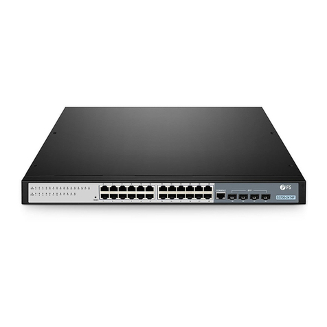
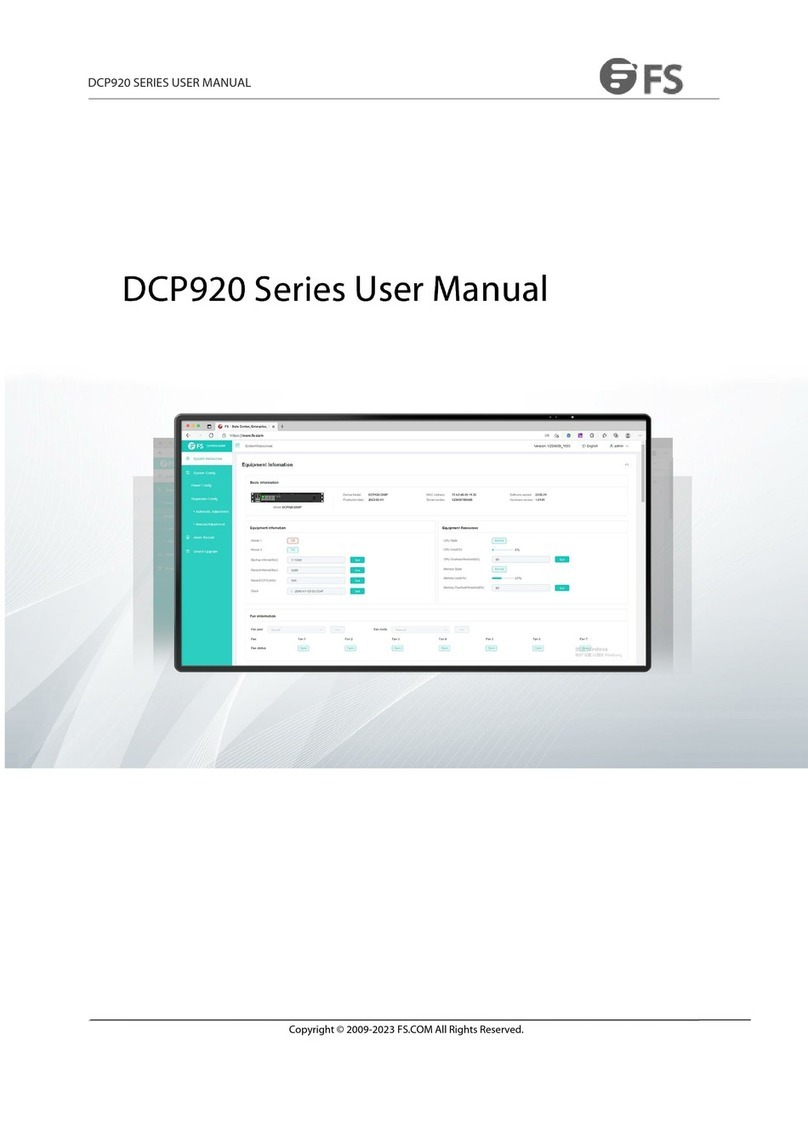
FS ONU2110-8GP User manual

GPON/EPON MDU ONU
ONU2110-8GP
GPON/EPON MDU ONU
GPON/EPON MDU ONU
V1.0
Quick Start Guide
Quick-Start Anleitung
Guide de Démarrage Rapide
ONU2110-8GP
Link/Act/Speed
Link/Act/Speed
SYS
PON
Reset
100M
1 3 5 7
7
9PON CLI
531
8642
9
POE
1000M
PWR 24 6 8
POE

1
Introduction
Thank you for choosing ONU2110-8GP GPON. This guide is designed to familiarize you with the
layout of the GPON and describes how to deploy it in your network.
ONU2110-8GP
Accessories
Mounting Bracket x2
M3 Screw x8Plastic Pad x4
Power Cord x1CLI Cable x1
POE
7
9PON CLI
53
1
8642
ONU2110-8GP
Link/Act/Speed
Link/Act/Speed
SYS
PON
Reset
100M
13579
1000M
PWR 2 4 6 8
POE
Stick ONU Module x1
EN

2
Front Panel
Hardware Overview
LED State Description
PWR
SYS
On
Blinking
Power indicator: If the device is powered on,
the indicator is on.
System indicator: If the device is started,
the system indicator ickers.
No.
1
LEDs
1 3
2
POE
7
9PON CLI
531
86
42
ONU2110-8GP
Link/Act/Speed
Link/Act/Speed
SYS
PON
Reset
100M
1357 9
1000M
PWR 2 4 6 8
POE
5 6 7 8 9 10
4
Optional(Not Included)
Screwdriver Static-proof wristband Bolt
Ethernet Cable
EN

3
LED State DescriptionNo.
O
Solid Yellow
O
O
On
Solid Green
Link/Act/Speed indicator of each port: 10/100M.
Link/Act/Speed indicator of each port: 1000M.
No signal transmission.
The PD is connected and the PoE power supply
is normal.
Gigabit TX
(1-8)
Solid Orange
Solid Green
POE
GSFP
(9)
2
3
The PD is not connected or PoE power is not provided.
Link/Act/Speed indicator of GSFP port: 1000M.
No signal transmission.
If the PON port is connected normally,
the indicator is on.
4
5PON
Button Description
Reset Keep the device power-on and press the button for about 6 seconds,
and the system default settings will be restored.
No.
6
Buttons
Port Description
Gigabit TX ports Forwards the 1000M Ethernet electric signals.
No.
7
GSFP port Forwards the 1000M Ethernet optical signals.8
PON port Connect to OLT through optical splitter.9
CLI port Console port. Connect to a computer or a terminal for
monitoring and conguring the device.
10
Ports
EN

4
Back Panel
Description
Grounding point.
AC power socket: AC100-240V.
No.
1
2
100-240V AC 50/60HZ
12
EN

5
Installation Requirements
Site Environment
Make sure that the installation site is well-ventilated and the heat of electrical devices
is well-discharged.
Make sure the temperature of installation site is maintained at 0-50°C.
Follow the electrostatic discharge prevention procedure.
Put the chassis at a place where cool air can blow o the heat inside the chassis.
Safety Recommendations
Keep clean and dust-free during or after the installation.
Put the cover of the GPON at a safe place.
Put tools at a right place where they will not easily fall down.
Pay attention to the dress code when installing. Avoid damage to the GPON caused
by improperly dressed.
Put on the protective glasses if the installation environment may cause damage to eyes.
Avoid improper operations that may cause personal injury or damage to the equipment.
Safety Principles for Live Working
Put o ornaments.
Pull out the AC power cord and close the direct-current power before operating on the chassis
or working beside the power supply.
Do not touch the power the when power is on.
Connect the device and the power socket correctly.
Only professionals are allowed to operate and maintain the device.
If you operate devices under live working, please follow the safety principles:
EN
TA2110-8GP
Link/Act/Speed
Link/Act/Speed
SYS
PON
Reset
100M
13579
POE
1000M
SYS 2468
POE

6
EN
Desk Mounting
Installation
Put the GPON on a smooth and safe desk directly.
Rack Mounting
1. Fix the mounting bracket to both sides of the GPON with screws.
ONU2110-8GP
Link/Act/Speed
Link/Act/Speed
SYS
PON
Reset
100M
1357
7
9PON CLI
5
31
8642
9
POE
1000M
PWR 2468
POE
Link/Act/Speed
Reset
7
9PON CLI
5
31
86
42
1000M
TA2110-8GP
TA2110-8GP

7
PWR SYS
1
24 6 8 10 12 14 1618 2022 24 26
PoE
28
2 5 7 9 11 13 1517 1921 23 25 27
Link/Act
Link/Act
RESET
S2800S-24T4F-P PoE+
2
143
PWR SYS
1
24 6 8 10 12 14 1618 2022 24 26
PoE
28
2 5 7 9 11 13 1517 1921 23 25 27
Link/Act
Link/Act
RESET
S2800S-24T4F-P PoE+
2
143
EN
Connecting the CLI Port
1. Insert the corresponding end of the CLI cable into the CLI port of the GPON.
2. Insert the other end of the CLI cable into the corresponding port of a computer host.
2. Mount the GPON on a rack by xing the mounting bracket to the rack.
Link/Act/Speed
Link/Act/Speed
SYS
PON
Reset
100M
1357
7
9PON CLI
531
8
6
42
9
POE
1000M
SYS 2468
POE
Link/Act/Speed
Link/Act/Speed
SYS
PON
Reset
100M
1357
7
9PON CLI
531
86
42
9
POE
1000M
SYS 2468
POE
8
Connecting the GSFP Port
1. Insert a GSFP optical module into the GSFP port of the GPON.
2. Connect the optical module to a switch or other Ethernet terminal devices with a ber cable.
Connecting Gigabit Ethernet TX Port
Connect the TX port of the GPON to a switch or other Ethernet terminal devices with a direct-through
or cross Ethernet cable.
465 87 109 1211 1413 1615 2019 2221 2423
18
17
SFP
ONU2110-8GP
Link/Act/Speed
Link/Act/Speed
SYS
PON
Reset
100M
1357
7
9PON CLI
531
8642
9
POE
1000M
PWR 24 6 8
POE
465 87 109 1211 1413 1615 2019 2221 2423
18
17
SFP
ONU2110-8GP
Link/Act/Speed
Link/Act/Speed
SYS
PON
Reset
100M
1357
7
9PON CLI
531
8642
9
POE
1000M
PWR 24 6 8
POE
EN

9
EN
Troubleshooting
If the GPON access device is too hot, check whether the air outlet and air inlet are clean.
If the GPON access device cannot be started and the Power indicator is o, check the power.
If the port of the GPON access device cannot be linked, check whether the cable is correctly
connected and whether the peer connection is normal.
If the CLI port does not work after the system is started up, check whether the CLI port is set to
a baud rate of 9600 bps, 8 data bits, no sum check bit, one stop bit and no trac control.
Connecting PON Port
1. Insert a Stick ONU module into the PON port of the GPON.
2. Connect the Stick ONU module to an optical splitter with a single-mode SC optical ber cable.
3. Then connect the splitter to an OLT with a ber cable.
P1 P3 P5 P7
CLI G1 G3 G1 G3 G5 G7
MGMT
OLT3610-08GP4S
ALM
G4 G8 T4 P4 P8
G1SYS G5 T1 P1 P5
P1
P2
T1 T2 T3 T4
ONU2110-8GP
Link/Act/Speed
Link/Act/Speed
SYS
PON
Reset
100M
1 3 5 7
7
9PON CLI
5
31
8642
9
POE
1000M
PWR 2 4 6 8
POE

Online Resources
Download
Help Center
Contact Us
https://www.fs.com/products_support.html
https://www.fs.com/service/fs_support.html
https://www.fs.com/contact_us.html
Product Warranty
FS ensures our customers that any damage or faulty items due to our workmanship, we will oer a
free return within 30 days from the day you receive your goods. This excludes any custom made items
or tailored solutions.
Warranty: The GPON enjoys 1 year limited warranty against defect in materials or
workmanship. For more details about warranty, please check at:
https://www.fs.com/policies/warranty.html
Return: If you want to return item(s), information on how to return can be found at:
https://www.fs.com/policies/day_return_policy.html
1
10
EN

11
Einführung
Vielen Dank, dass Sie sich für ONU2110-8GP GPON entschieden haben. Diese Anleitung soll Sie mit
dem Aufbau vom GPON vertraut machen und beschreibt, wie Sie es in Ihrem Netzwerk einsetzen
können.
ONU2110-8GP
Zubehör
Montagehalterung x2
M3-Schraube x8Kunststopad x4
Netzkabel x1CLI-Kabel x1
POE
7
9PON CLI
53
1
8642
ONU2110-8GP
Link/Act/Speed
Link/Act/Speed
SYS
PON
Reset
100M
13579
1000M
PWR 2 4 6 8
POE
ONU-Stick-Modul x1
DE

12
Vorderseite
Hardware-Übersicht
LED Status Beschreibung
PWR
SYS
An
Blinkt
Stromanzeige: Wenn das Gerät eingeschaltet ist,
leuchtet die Anzeige.
Systemanzeige: Wenn das Gerät gestartet wird,
blinkt die Systemanzeige.
Nr.
1
LEDs
1 3
2
POE
7
9PON CLI
531
8642
ONU2110-8GP
Link/Act/Speed
Link/Act/Speed
SYS
PON
Reset
100M
13579
1000M
PWR 24 6 8
POE
56 7 8 9 10
4
Optional (nicht im Lieferumfang enthalten)
Schraubendreher Statiksicheres Handgelenkband Bolzen
Ethernet-Kabel
DE

13
LED Status Beschreibung
Nr.
Aus
Durchgehend
Gelb
Aus
Aus
An
Durchgehend
Grün
Link/Act/Speed-Anzeige für jeden Port: 10/100M.
Link/Act/Speed-Anzeige für jeden Port: 1000M.
Keine Signalübertragung.
Der PD ist angeschlossen und die PoE-Stromversorgung
ist normal.
Gigabit TX
(1-8)
Durchgehend
Orange
Durchgehend
Grün
POE
GSFP
(9)
2
3
Der PD ist nicht angeschlossen oder PoE-Strom ist nicht
vorhanden.
Link/Act/Speed-Anzeige des GSFP-Ports: 1000M.
Keine Signalübertragung.
Wenn der PON-Port normal angeschlossen ist,
leuchtet die Anzeige.
4
5PON
Taste Beschreibung
Reset
Lassen Sie das Gerät eingeschaltet und drücken Sie die Taste ca.
6 Sekunden lang, dann werden die Standardeinstellungen des
Systems wiederhergestellt.
Nr.
6
Tasten
Port Beschreibung
Gigabit TX ports Leitet die elektrischen 1000M-Ethernet-Signale weiter.
Nr.
7
GSFP-Port Leitet die optischen 1000M-Ethernet-Signale weiter.8
PON-Port Verbindung zum OLT über einen optischen Splitter.9
CLI-Port Console-Port. Anschluss an einen Computer oder ein Terminal
zur Überwachung und Konguration des Geräts.
10
Ports
DE

14
Back Panel
Beschreibung
Erdungspunkt
AC-Steckdose: AC100-240V.
Nr.
1
2
100-240V AC 50/60HZ
12
DE

15
Installationsvoraussetzungen
Standortumgebung
Stellen Sie sicher, dass der Installationsort gut belüftet ist und die Wärme der elektrischen Geräte
gut abgeleitet wird.
Achten Sie darauf, dass die Temperatur am Installationsort zwischen 0°C und 50°C liegt.
Beachten Sie das Verfahren zur Vermeidung elektrostatischer Entladungen.
Stellen Sie das Gehäuse an einem Ort auf, an dem kühle Luft die Wärme im Inneren des Gehäuses
abführen kann.
Sicherheitsempfehlungen
Halten Sie das Gerät während und nach der Installation sauber und staubfrei.
Legen Sie die Abdeckung des GPON an einen sicheren Ort.
Legen Sie die Werkzeuge an einem Ort ab, an dem sie nicht leicht herunterfallen können.
Achten Sie bei der Installation auf die Kleiderordnung. Vermeiden Sie Schäden am GPON,
die durch unsachgemäße Kleidung verursacht werden.
Setzen Sie eine Schutzbrille auf, wenn die Installationsumgebung zu Augenschäden führen kann.
Vermeiden Sie unsachgemäße Arbeiten, die zu Verletzungen oder Schäden an der Ausrüstung
führen können.
Sicherheitsgrundsätze für Arbeiten unter Spannung
Legen Sie Schmuck ab.
Stecken Sie den Netzstecker aus und schalten Sie die Gleichstromversorgung ab, bevor Sie am
Gehäuse oder neben dem Netzteil arbeiten.
Berühren Sie das Netzgerät nicht, wenn es eingeschaltet ist.
Schließen Sie das Gerät an die Steckdose richtig an.
Nur Fachleute dürfen das Gerät bedienen und warten.
Wenn Sie Geräte unter Spannung bedienen, beachten Sie bitte die Sicherheitsgrundsätze:
DE
TA2110-8GP
Link/Act/Speed
Link/Act/Speed
SYS
PON
Reset
100M
1357 9
POE
1000M
SYS 2468
POE
16
DE
Montage auf einem Tisch
Installation
Stellen Sie den GPON direkt auf einen glatten und sicheren Tisch.
Rack-Montage
1. Befestigen Sie die Halterung mit Schrauben an beiden Seiten des GPONs.
ONU2110-8GP
Link/Act/Speed
Link/Act/Speed
SYS
PON
Reset
100M
1357
7
9PON CLI
5
31
8642
9
POE
1000M
PWR 2468
POE
Link/Act/Speed
Reset
7
9PON CLI
5
31
86
42
1000M
TA2110-8GP
TA2110-8GP

17
PWR SYS
1
24 6 8 10 12 14 1618 2022 24 26
PoE
28
2 5 7 9 11 13 1517 1921 23 25 27
Link/Act
Link/Act
RESET
S2800S-24T4F-P PoE+
2
143
PWR SYS
1
24 6 8 10 12 14 1618 2022 24 26
PoE
28
2 5 7 9 11 13 1517 1921 23 25 27
Link/Act
Link/Act
RESET
S2800S-24T4F-P PoE+
2
143
DE
Anschließen des CLI-Ports
1. Stecken Sie das entsprechende Ende des CLI-Kabels in den CLI-Port des GPON.
2. Stecken Sie das andere Ende des CLI-Kabels in den entsprechenden Anschluss eines
Computer-Hosts.
2. Montieren Sie den GPON auf einem Rack, indem Sie die Montagehalterung am Rack befestigen.
Link/Act/Speed
Link/Act/Speed
SYS
PON
Reset
100M
1357
7
9PON CLI
531
86
42
9
POE
1000M
SYS 2468
POE
Link/Act/Speed
Link/Act/Speed
SYS
PON
Reset
100M
1357
7
9PON CLI
531
8
6
42
9
POE
1000M
SYS 2468
POE

18
Anschließen des GSFP-Ports
1. Stecken Sie ein optisches GSFP-Modul in den GSFP-Port des GPON.
2. Schließen Sie das optische Modul mit einem Glasfaserkabel an einen Switch oder andere
Ethernet-Endgeräte an.
Anschließen des Gigabit-Ethernet-TX-Ports
Verbinden Sie den TX-Port des GPON mit einem Switch oder anderen Ethernet-Endgeräten mit einem
Direct-Through- oder Cross-Ethernet-Kabel.
465 87 109 1211 1413 1615 2019 2221 2423
18
17
SFP
ONU2110-8GP
Link/Act/Speed
Link/Act/Speed
SYS
PON
Reset
100M
1357
7
9PON CLI
531
8642
9
POE
1000M
PWR 24 6 8
POE
465 87 109 1211 1413 1615 2019 2221 2423
18
17
SFP
ONU2110-8GP
Link/Act/Speed
Link/Act/Speed
SYS
PON
Reset
100M
1357
7
9PON CLI
531
8642
9
POE
1000M
PWR 24 6 8
POE
DE

P1 P3 P5 P7
CLI G1 G3 G1 G3 G5 G7
MGMT
OLT3610-08GP4S
ALM
G4 G8 T4 P4 P8
G1SYS G5 T1 P1 P5
P1
P2
T1 T2 T3 T4
ONU2110-8GP
Link/Act/Speed
Link/Act/Speed
SYS
PON
Reset
100M
1 3 5 7
7
9PON CLI
5
31
8642
9
POE
1000M
PWR 2 4 6 8
POE
19
DE
Fehlersuche
Wenn das GPON-Zugangsgerät zu heiß ist, prüfen Sie, ob der Luftaustritt und der Lufteintritt
sauber sind.
Wenn das GPON-Zugangsgerät nicht gestartet werden kann und die Betriebsanzeige nicht
leuchtet, überprüfen Sie die Stromversorgung.
Wenn der Port des GPON-Zugangsgeräts nicht verbunden werden kann, prüfen Sie, ob das Kabel
richtig angeschlossen ist und ob die Peer-Verbindung normal ist.
Wenn der CLI-Port nach dem Hochfahren des Systems nicht funktioniert, prüfen Sie,
ob der CLI-Port auf eine Baudrate von 9600 bps, 8 Datenbits, kein Summenprüfbit, ein Stoppbit
und keine Datenverkehrskontrolle eingestellt ist.
Anschließen des PON-Ports
1. Stecken Sie ein ONU-Stick-Modul in den PON-Port des GPON.
2. Verbinden Sie das ONU-Stick-Modul mit einem optischen Splitter über ein
Singlemode-SC-Glasfaserkabel.
3. Verbinden Sie dann den Splitter über ein Glasfaserkabel mit einem OLT.
Table of contents
Languages:
Other FS Network Hardware manuals
Popular Network Hardware manuals by other brands

Sunrise
Sunrise CONNECT BOX 3 Quick install guide

LaCie
LaCie D2 BLU-RAY XL Quick install guide

Huawei
Huawei V600R019C00 Product description

HP
HP X1600 - StorageWorks Network Storage System 5.4TB SAS Model NAS... installation instructions

AXIOMTEK
AXIOMTEK NA345 Series user manual

Russound
Russound BGB2 instruction manual