FCC ID: 2ALMLPBSC
This device complies with Part 15 of the FCC Rules.Operation is subject to the following two conditions:
(1) this device may not cause harmful interference and
(2) this device must accept any interference received, including interference that may cause undesired operation of the device.
This equipment has been tested and found to comply with the limits for a Class B digital device, pursuant to part 15 of the FCC
rules. These limits are designed to provide reasonable protection against harmful interference in a residential installation.
This equipment generates, uses and can radiate radio frequency energy and, if not installed and used in accordance with the
instructions, may cause harmful interference to radio communications. However, there is no guarantee that interference will not
occur in a particular installation. If this equipment does cause harmful interference to radio or television reception, which can be
determined by turning the equipment off and on, the user is encouraged to try to correct the interference by one or more of the
following measures:
-Reorient or relocate the receiving antenna.
-Increase the separation between the equipment and receiver.
-Connect the equipment into an outlet on a circuit different from that to which the receiver is connected.
-Consult the dealer or an experienced radio/TV technician for help.
You are cautioned that changes or modifications not expressly approved by the part responsible for compliance could void the
user’s authority to operate the equipment.
FCC RF Radiation Exposure Statement:
1. This Transmitter must not be co-located or operating in conjunction with any other antenna or transmitter.
2. For body worn operation, this device has been tested and meets FCC RF exposure guidelines. When used with an accessory
that contains metal may not ensure compliance with FCC RF exposure guidelines.
FCC Statement
IC: 22650-PBSC
This device contains licence-exempt transmitter(s)/receiver(s) that comply with Innovation, Science and Economic Development
Canada’s licence-exempt RSS(s). Operation is subject to the following two conditions:
1. This device may not cause interference, and
2. This device must accept any interference, including interference that may cause undesired operation of the device.
L’émetteur/récepteur exempt de licence contenu dans le présent appareil est conforme aux CNR d’Innovation, Sciences et
Développement économique Canada applicables aux appareils radio exempts de licence. L’exploitation est autorisée aux deux
conditions suivantes :
1. l'appareil ne doit pas produire de brouillage, et.
2. l'utilisateur de l'appareil doit accepter tout brouillage radioelectrique subi, meme si le brouillage est susceptible d'en
compromettre le fonctionnement.
Caution: Exposure to Radio Frequency Radiation
1. To comply with the Canadian RF exposure compliance requirements, this device and its antenna must not be co-located or
operating in conjunction with any other antenna or transmitter.
2. For body worn operation, this device has been tested and meets RF exposure guidelines when used with an accessory that
contains no metal. Use of other accessories may not ensure compliance with RF exposure guidelines.
Attention: exposition au rayonnement radiofréquence
1. Pour se conformer aux exigences de conformité RF canadienne l'exposition, cet appareil et son antenne ne doivent pas être
co-localisés ou fonctionnant en conjonction avec une autre antenne ou transmetteur.
2. Pour une utilisation sur le corps, cet appareil a été testé et respecte les directives sur l'exposition aux RF lorsqu'il est utilisé avec
un accessoire sans métal. L'utilisation d'autres accessoires peut ne pas garantir la conformité aux directives d'exposition aux RF.
LP0002低功率射頻器材技術規範_章節3.8.2
取得審驗證明之低功率射頻器材,非經核准,公司、商號或使用者均不得擅自變更頻率、加大功率或變更原設計之特性及功能。
低功率射頻器材之使用不得影響飛航安全及干擾合法通信;經發現有干擾現象時,應立即停用,並改善至無干擾時方得繼續使用。
前述合法通信,指依電信管理法規定作業之無線電通信。低功率射頻器材須忍受合法通信或工業、科學及醫療用電波輻射性電機設
備之干擾。
IC Statement
NCC警語
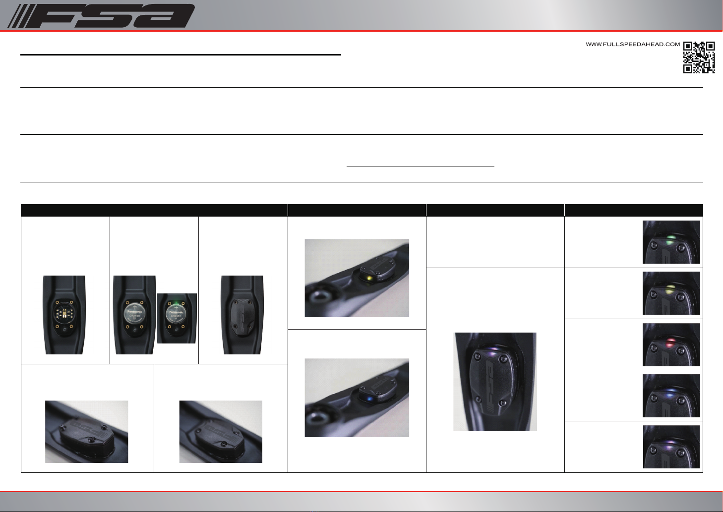
RISK OF EXPLOSION IF BATTERY IS REPLACED BY AN INCORRECT TYPE. DISPOSE OF USED
BATTERIES ACCORDING TO THE INSTRUCTIONS.
I
C
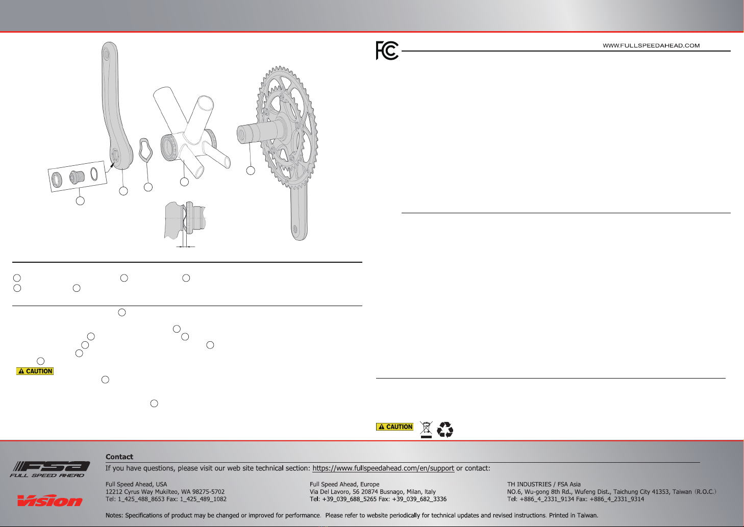
68mm Bottom Bracket Shell
Do not tighten crank bolt over 418 kgf.cm / 41 Nm / 363 in.lbs. Try to avoid completely flattening the wave
spring washer ③. Clearance between non-drive arm and bearing shield should be 1.5 - 2.0mm. If the
clearance is not within 1.5 - 2.0mm after applying correct torque, DO NOT tighten the crank bolt further.
Recheck installation procedure and order of assembled parts. Otherwise may cause bolt tighten torque
reduced, evevn left crank loose ④Always use a calibrated torque wrench to tighten crank bolt. Stripping
or breakage due to installing without a torque wrench is NOT covered under manufacturing warranty.
Follow the assembly order in the illustration:
Crankset Installation
1. Ensure the Bottom Bracket Shell ①is compatible.
(Note : Follow the BB installation instruction for BB will be installed).
2. Apply a thin layer of grease on the spindle surfaces ②which contact bearing.
3. Insert the drive crank ②into the right side of BB shell ①.
4. Place Wave Washer ③onto the Spindle. Install Left Crank Arm ④onto the axle.
5. Ensure crank bolt ⑤is pre-installed on axle. Using a torque wrench with 10mm allen key tighten the Crank
Bolt ⑤to 388-418 kgf.cm / 38-41 Nm / 336-363 in.lbs.
Note: After complete crankset installation the initial rotation torque 5 kgf.cm / 0.5 Nm / 4.4 in.lbs (inclusive) is normal and
safe to use!
2
21
3
3
4
4
5
5
1
1
23
45
Right Crank x1 Wave Spring Washer x1
Left Crank x1 Crank Bolt Assembly for Left crank x1
Components
3
4
2
1
5
Clearance between non-drive arm 1.5 – 2.0 mm