Wiring Installation Tips
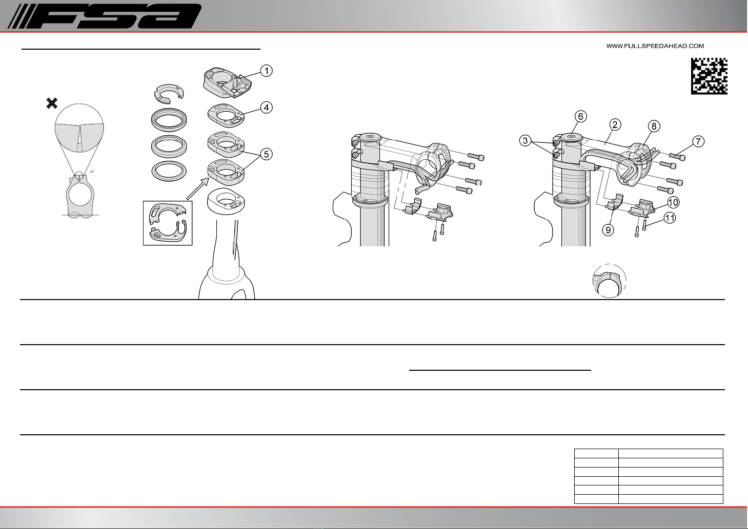
1. Before proceedingto installation,all Brake/HydraulicHose /electronicwiring/shouldbe run through the handlebar andNS SMR StemBody ②orSpacer andSpacers,SMR headset④⑤ .(Fig. B)
2. SMR Stemshave two optionsforcable routing. When usinghandlebars withinternal routingports, the housings andelectronicwirescan be routedthroughthe StemBody ②.Alternativly,the housings andelectronic
wirescan be routedbeneath the Stem Body andthrough the cover ⑩andSpacers ⑨.
3. Front brake housings can only be internally routedfordiscbrakes. Compatible forkshave aninternal routingport on the steerertube (Fig. B).All otherfront brake housings must be routedexternally.
4.Dependingonstemlength you may needto install upto 3x Cable CoverSpacers ⑨.
5. Installation isgreatly improvedwhen usingaguide cable to gently pull the housingorelectronicwiresthrough the stemfromeitherdirection.
StemInstallation to ForkSteerer Tube
1. Measure diameterofsteerertube to be certain it iscorrect size forSMR steminstallation.It soften requiredthat the steerertube be cut to length andshouldbe performedby aqualifiedbicycle technician.Ensure the
steerertube isclean andfree ofburrsorchips before installingstemonto steerertube.
Note:Carbon steerertubesshouldextendthrough the stemcompletely forproperclamppressure.It isrecommendedto have minimum2mm steerertube extendedabove the stem.
2. Install fork through the Stem Body ②,place the spacers overthe fork andthen accordingto yourdemandplace left/right spacers ,(,④⑤④⑤are detachable,figA).
3. Headset shouldbe installedperheadset manufacturer sinstructions.
4.Apply small amount ofFSA Dynamicinstallation compoundon Carbon steerertube.Install the ExpanderAssembly (not shown) perExpanderAssembly instructionsbelow.
5. Apply grease to stemfixingbolts ③.Tighten the boltsto 60 kgf.cm /6Nm/53 in.lbs. oftorque by alternatingbetween bolts1/4turn at atime so both boltsreach propertorque simultaneously.
Do not go above maximumtorque ratingprintedon the stem.Ifyoursteererclamplookslike Fig. C it may be overtorquedorinstalledincorrectly.Iftwo FixingBolts ③go overthe maximumtorque,can
cause cracksin carbon steerertube.Check stemforslippage on the steerertube before proceeding.
Expander Assembly Installation
The ExpanderAssembly isdesignedto work with Carbon SteererTubes. Do not apply grease on the Carbon SteererorExpanderAssembly.
1. Install the Stemontothe Carbon Steerer.Tighten the SteererClampBoltsfingertight only.②③
2. Adjust ExpanderAssembly soit contactsthe innerwallsofthe steerertube but isstill able to slide inside.Install the pre-adjustedExpanderAssembly.Tighten the ExpanderAssembly with a5mm hex wrenchto 50
kgf.cm /5Nm/45 in.lbs. oftorque.Note:The ExpanderAssembly must be complete assembledandadjustedtofit tightly into the Carbon Steererbefore installation.
3. Tighten the TopCap ⑥with a6mm hex wrench to until properbearingpreload isachieved. Note:Properbearingpreloadisapparent when there isno “knock”(fore /aft orup/down free play) in the headset
assembly,while the bearings rotate freely (free steeringmotion).
Check thealignment ofStemtothe front wheelbefore final torque isappliedto the SteererClampBolts, loosen andadjust ifrequired. Be sureall boltsare tightenedto recommendedtorque.
Handlebar Installation to Stem
1. Apply FSA DynamicInstallation Compoundon handlebarclamparea. Insert handlebarbetween NS SMR StemBody andface plate②⑧Pre-tighten Face Plate Fixingbolts ⑦.
2. Apply grease to faceplate boltsandtighten the upperboltsto atorque 60kgf.cm /6Nm/53 in.lbs Alternately tighten TOP stemboltsuntil there isno gap between faceplate andstembody.(Fig. D).
3. Tighten the lowerboltsto atorque 60kgf.cm/6Nm/53 in.lbs 1/4turn at atime totighten faceplate evenly.
Do not go above maximumtorque ratingprintedon the stem.Check handlebar forslippage before each ride toensure safe operation.Contact FSA forTroubleshootinginformation.
Be sure to choose the correct stemto fit the steertube andhandlebar forwhich it isto be installed. Installingthe stemon an incorrect steerertube,orhandlebar clampdiametermay cause damage to product,or
cause an accident resultingin injury ordeath.
lFSA NS SMR stemsare designedto work with 1 1/8”steertubes.(Apply small amount ofFSA Dynamicinstallation compoundon steerertube andstem)
lFSA Road andMTBstemsare available to fit 31.8mm Handlebarclamponly.
Measure Fork Steerertube andhandlebar clamp areabefore installingstem.Use an accurate measuringdevice such as acaliperormicrometer.Installingstemonto an undersizedsteertube orhandlebar can cause stemor
bar to slipcausingloss ofcontrol ofbicycle;resultingin an accident,damage tobicycle,injury ordeath.Use FSA DynamicAssembly Paste between stem,steerertube,andhandlebar to reduce chancesofslippage.
Consult fork andhandlebarmanufacturerforexact diameterspecification.Ifmanufacturerspecificationsare unavailable,general guidelinesare as follows:
Headset andFork must be installedbefore steminstallation.Headset andFork installation requiresspecializedknowledge,tools,andexperience.General mechanical aptitude may not be sufficient to properly install these
components. It isrecommendedthat the headset andfork be installedby aqualifiedbicycletechnician.Improperinstallation canresult in failure ofheadset,fork,stem,andcause personal injury ordeath.
Handlebar ClampAreaDimensions:
lΦ31.8mm + 0.15/-.00mm
lΦ26.0mm + 0.15/-.00mm
lΦ25.4mm + 0.15/-.00mm
l11/8”Φ28.6mm +.01 /-.00mm
l11/4”Φ31.8mm +.01 /-.00mm
l1.5”Φ38.1mm +.01 /-.00mm