FSC 737NG User manual

2
B737 TILLER PRO - REAL FORCE FEEDBACK

TABLE OF CONTENTS
CHAPTER 1. OVERVIEW................................................................. 4
1.1 BOX CONTENT AND FEATURES ................................................4
CHAPTER 2. INSTALLATION ....................................................... 6
2.1 HARDWARE INSTALLATION.......................................................6
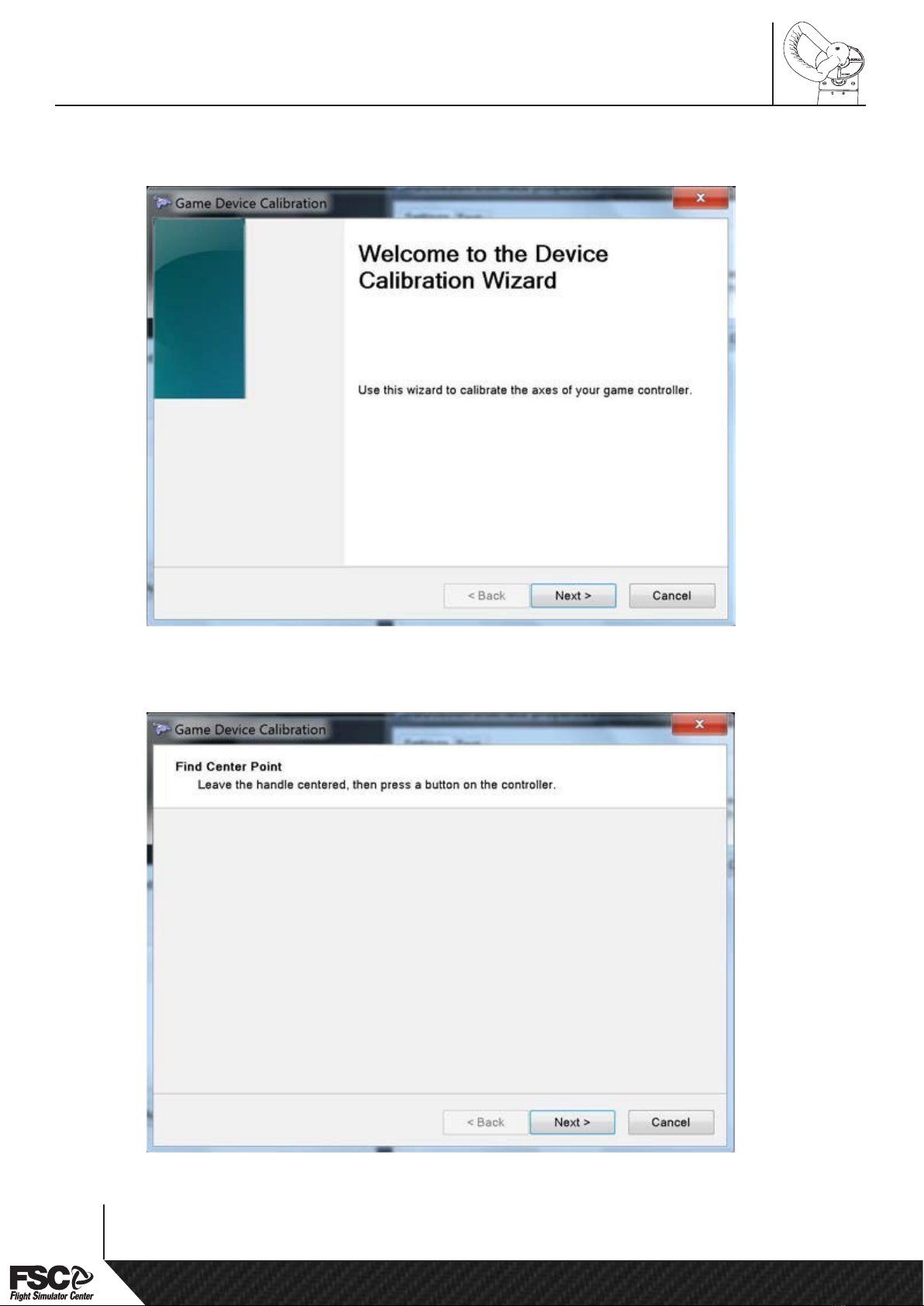
2.2 SOFTWARE SETTINGS AND CALIBRATION..............................7
CHAPTER 3. SETUP .......................................................................... 14
3.1 ADJUSTING THE REACTION FORCE AND RETURN TO
ZERO SPEED...................................................................................... 14
APPENDIX A
A1 DIMENSION AND WEIGHT .............................................................15
APPENDIX B
B1 SCHEMATICS ...................................................................................17
APPENDIX C
C1 DRILLING TEMPLATE......................................................................18
APPENDIX D
D1 POTENTIOMETER REPLACEMENT................................................19
APPENDIX E
E1 MECHANICAL RE-ALIGNMENT / LOOSING THE KEYLESS
LOCKING DEVICE .................................................................................21
HOW TO CONTACT SUPPORT ...........................................................22
DISCLAIMER
All product names, logos, and brands are property of their respective owners.
www.fsc.it
Installation and Operation Manual
3

CHAPTER 1. OVERVIEW
1.1 BOX CONTENT AND FEATURES
FSC 737NG TILLER PRO provides greater control of the aircraft during taxi operations.
FSC 737NG TILLER PRO kit (CPT side SKU.289147shown), is composed by the following items:
ment Division of Professional Show SpA - 35010 LIMENA (PD) - ITALY
1
2
3
45
6
7
8
A
B
C
D
E
1. 737NG Tiller pro (Built-in USB Interface)
2. Countersunk hex head screws (M5x30)
3. Indicator plates, white and black (CPT or F/O)
4. Phillips + at screws (M4x16)
5. Feather key (spare)
6. Spare/adjustment Washers (3 mm/each
thickness)
7. Steering tiller handle (CPT or F/O)
8. Handle Allen Screw (M5x20) + split washer
A) USB Cable
B) Drilling template
C) Usb key with documentation
D) Plug for custom USB interface
E) Allen Keys
4
B737 TILLER PRO - REAL FORCE FEEDBACK

A) USB Cable
B) Drilling template
C) Usb key with documentation
D) Plug for custom USB interface
E) Allen Keys
The FSC 737NG TILLER PRO kit is a no-compromise, reliable solution built for intensive use and
ultimate realism, and provides very exible features, letting to use it in a huge variety of situations
and with most simulation software currently available:
• Solid body built with precision CNC machined parts, made of aluminium, Ergal aircraft alloy
and special steels. Designed and tested to withstand over 500.000 actuations
• With a system of springs and double torque cam mechanism the reaction force is always
controlled, matching in realism the original hydraulic one
• Adjustable reaction force
• Smooth and harmless return to zero, through the use of a 0-MAX adjustable damper
• USB plug and play connection (no driver required)
• Easy access to electronic components
• Both black and white rotary engraved indicator plates provided, to suit your cockpit style
www.fsc.it
Installation and Operation Manual
5

CHAPTER 2. INSTALLATION
2.1 HARDWARE INSTALLATION
FSC 737NG TILLER PRO provides greater control of the aircraft during taxi operations.
B
7
4
2 3
8
5 6
1
Fig.1 - Drilling template (B)- (see Chapter
1.1) + spirit level.
Fig.2 – Tiller body (1) on side panel.
Fig.3 – Assembly sequence (2 to 8) (see Chapter 1.1 for items detail).
(not needed for FSC shell sides)
6
B737 TILLER PRO - REAL FORCE FEEDBACK

(not needed for FSC shell sides)
2.2 SOFTWARE SETTINGS AND CALIBRATION
Generic Game Controller settings (to be calibrated before conguring FSUIPC or XPLANE)
Plug the usb cable into PC. Press “START” menù and type “Joy.cpl”
(Fig.1)
Click on “Properties” and calibrate.
(Fig.2)
www.fsc.it
Installation and Operation Manual
7

Conrm wizard with NEXT button
(Fig.3)
Find center point and conrm with NEXT button
(Fig. 4)
8
B737 TILLER PRO - REAL FORCE FEEDBACK

XPLANE ONLY: One Tiller AXIS
From “Settings” menu, select “Joystick, Keys & equipment”, select “axis” tab, move tiller to discover
the axis, then assign it from the dropbox to “ Nose-wheel steering tiller”.
FSX/P3D ONLY : NO Tiller AXIS, together with Rudder AXIS
FSX/P3D With FSUIPC: One Tiller AXIS
From “add ons” menu, select “FSUIPC”, select “Axis assignment” tab, move the tiller to discover
the axis, then under “type of action required” select the radio button “send direct to FSUIPC
calibration”, select”Steering Tiller” from dropbox menu.
10
B737 TILLER PRO - REAL FORCE FEEDBACK

From “Joystick calibration” tab, select “Pan axes (etc)” page.
From “Steering Tiller(direct!)” move the tiller to discover min,center & max values then press “Set”
buttons to conrm values..
Magenta FBW with XPLANE/FSX/P3d: Two separate Tiller AXIS
From FBW main page press “Calibrate” move Tiller to discover the axis. Near the axis press “Sel” to
select and calibrate.
www.fsc.it
Installation and Operation Manual
11

Under the calibration page select “Assign” button to assign the Axis “Tiller” or “Tiller F/O”.
12
B737 TILLER PRO - REAL FORCE FEEDBACK

Tiller direction: rotating the handle downward the “out” indicator must slide to the left, if not,
select “Inverted” (arrow 1).
Press “Recalibrate” (arrow 2) and move the tiller left and right slowly to calibrate the axis.
Look at the input and output values (arrow 3): the “in” value above indicate the raw values from
joystick interface, the “out” value below indicates the calculated range of values to send to
simulator according to calibration ltered by “Tiller response Curve”.
Release the handle to center the tiller, and press “Set Center” (arrow 4) How to change Response
Curve:
Drag with mouse:
“Null” (arrow 5) to change null zone value (right to enlarge), “Width”(arrow 6) for width zone,
“Max” (arrow 7) for % max excursion.
The Output Axis will move between “Null” and “Wdth”, with deection from 0% to “Max”
% of calibrated value (arrow 3, “out”)
Then click:
“Default” (arrow 8) for straight response,
“Curve” (arrow 9) for progressive response (like in the picture).
You can draw your own curve directly with your mouse pointer (arrow 10). To end calibration
process, click “Lock Calibration” (arrow 11).
www.fsc.it
Installation and Operation Manual
13

CHAPTER 3. SETUP
3.1 ADJUSTING THE REACTION FORCE AND RETURN TO ZERO SPEED
Reaction force adjustment (unit is factory-calibrated to optimal feeling)
Return to zero speed adjustment ( every Tiller is factory-calibrated to optimal feeling )
CAUTION - Turn the screw few degrees at a time.
ADJUSTABLE
DAMPING
ADJUSTABLE
FORCE
FEEDBACK
2.0>6.2 Kg
14
B737 TILLER PRO - REAL FORCE FEEDBACK

03
02
01
REV.
NDISEGNO:
Data
FOGLIO
PROGETTO:
0,2
0,8
1,6
MASSIMO GRADO DI
RUGOSITA' AMMESSA
SCALA
0,5 / /0,3
0,20,15
0,1
0,05
1,2 23
0,8
0,5
0,3
0,2
0,1
345
21,2
0,8
0,5
0,2
PRECISO
MEDIO
GROSSOLANO
Progettista/Designer
APPROVATO
EMISSIONEDESCRIZIONE
REV.
Questo disegno è di proprietà della
Professional Show S.p.A.
Via Praimbole, 15
35010 LIMENA (PD)
Ph: +39.049.8657111
La riproduzione e divulgazione,
anche parziale, è vietata ai sensi
delle norme vigenti.
UNI EN ISO 22768
SE NON DIVERSAMENTE SPECIFICATO:
TUTTE LE PIEGHE SONO A 90
ALTEZZA SALDATURE 0,7 VOLTE LO SPESSORE MINIMO DEL
MATERIALE
QUANTITA'
SVILUPPO mm
PESO Kg
SUPERFICIALE
TRATTAMENTO
MATERIALE
TOLLERANZE GENERICHE PER QUOTE DI LAVORAZIONE ( UNI 5307-63 )
segnare con una croce il grado di precisione indicato per questo particolare
GRADO DI PRECISIONE < 6 6 - 30 30 - 120 120 - 315 315 - 1000 1000 - 20002000 - 4000 > 4000
RIMUOVERE EVENTUALI
BAVE DI LAVORAZIONE
3,2
A2
14/03/2023
1 di 1
1:2
Luca Pranovi
289146-00 Tiller passivo 737 rev1
236. 5
1 0 2
3 0 1
9 0
1 8 3
APPENDIX A - A1 DIMENSION AND WEIGHT
*Dimensions in metric units (mm). Weight is 4 Kgs / 8.6 lbs
www.fsc.it
Installation and Operation Manual
15

03
02
01
REV.
NDISEGNO:
Data
FOGLIO
PROGETTO:
0,2
0,8
1,6
MASSIMO GRADO DI
RUGOSITA' AMMESSA
SCALA
0,5 / /
0,3
0,2
0,15
0,1
0,05
1,2 2 3
0,80,5
0,30,20,1
34521,2
0,80,5
0,2
PRECISO
MEDIO
GROSSOLANO
Progettista/Designer
APPROVATO
EMISSIONEDESCRIZIONE
REV.
Questo disegno è di proprietà della
Professional Show S.p.A.
Via Praimbole, 15
35010 LIMENA (PD)
Ph: +39.049.8657111
La riproduzione e divulgazione,
anche parziale, è vietata ai sensi
delle norme vigenti.
UNI EN ISO 22768
SE NON DIVERSAMENTE SPECIFICATO:
TUTTE LE PIEGHE SONO A 90
ALTEZZA SALDATURE 0,7 VOLTE LO SPESSORE MINIMO DEL
MATERIALE
QUANTITA'
SVILUPPO mm
PESO Kg
SUPERFICIALE
TRATTAMENTO
MATERIALE
TOLLERANZE GENERICHE PER QUOTE DI LAVORAZIONE ( UNI 5307-63 )
segnare con una croce il grado di precisione indicato per questo particolare
GRADO DI PRECISIONE < 6 6 - 30 30 - 120 120 - 315 315 - 1000 1000 - 2000 2000 - 4000 > 4000
RIMUOVERE EVENTUALI
BAVE DI LAVORAZIONE
3,2
A2
14/03/2023
2 di 2
1:2
Luca Pranovi
289146-00 Tiller passivo 737 rev1
22. 5 22. 5
4 5
36. 5 41. 5
7 8
N°4 M5 mounting
threaded holes
Damping regulation
Force regulation
16
B737 TILLER PRO - REAL FORCE FEEDBACK

0 1 2 3 4 5 6 7 8 9 10
APPENDIX C - C1 DRILLING TEMPLATE
*This template is 1:1 scale. Please check with provided reference scale before drilling.
18
B737 TILLER PRO - REAL FORCE FEEDBACK

4
6
5
2 mm Metric
5/64 inches SAE
7
FOR CORRECT CALIBRATION,
POTENTIOMETER GEAR
MUST BE ALIGNED AS IN FIGURE
90,00 Deg
Please check potentiometer mechanical calibration (see Chapter 2.2 for procedure and Fig.5 for raw
data value reading).
Pot is mechanically centered when X Axis value is as close to 2048 as possible
20
B737 TILLER PRO - REAL FORCE FEEDBACK
Other manuals for 737NG
1
Table of contents
Popular Educational Equipment manuals by other brands

Enabling Devices
Enabling Devices Switch & Glow user guide

Pitsco Education
Pitsco Education Wind Gen Plus Kit user guide

Nienhuis
Nienhuis TURN OVER NATURE instructions

Ambu
Ambu Airway Management Trainer Directions for use

Aircatglobal
Aircatglobal VirtualFly VERNIO manual

ADEEPT
ADEEPT Ultimate Sensor Kit for Raspberry Pi manual