manuals.online logo
Brands
  1. Home
  2. •
  3. Brands
  4. •
  5. FSH
  6. •
  7. Lock
  8. •
  9. FSH FEM3500 User manual

FSH FEM3500 User manual

FEM3500/FEM3500D/FEM3500M/FEM3500DM
Electromagnetic Lock
Electro-Magnetic Lock Description:
Power setting and Input
Wiring connections:
The FEM3500 is an unmonitored single magnetic lock and FEM3500D is an unmonitored double magnetic
lock with dual 12 or 24 volt settings. There are no Lock or Door status sensors on these units. For wiring
instruction refer to figure 2.
The FEM3500M is a monitored single magnetic lock and the FEM3500DM is a monitored double
magnetic lock with 12 or 24 volt settings. Each magnetic lock has a built-in Hall crystal for remote
monitoring of Lock status (open or closed) through relay contacts rated at 24 VDC, 1.0 A max on
visible high luminosity backlight indicator position on the aluminum housing and a Door Status
Sensors (DSS) for remote monitoring of Door status through reed switch contact. For wiring
instruction refer to Figure 1.
The (+) lead of the power source is connected to Pins 1 (VDC +) of the terminal block and the (-) lead
is connected to Pin 2 (-). The operating switch or controlling contacts must be installed between the
power source and the magnetic lock to reduce operating time of the magnetic lock to a minimum. The
electromagnetic lock requires a filtered and regulated DC Power Source for optimal performance.
Remove the wiring cavity cover plate and check the position of the two shunts located on the PCB. A
single shunt across pins 2 and 3 will set the operating voltage to 24 volts. A shunt between pins 1 to
2 and a shunt between pins 3 to 4 sets the operating voltage to 12 volts.
These voltage shunts must be set correctly before 12 VDC or 24 VDC power is supplied to the
Electromagnetic Lock to prevent damage to the unit.
12341234
-
_
LED LIGHT PANEL
RBG
RBG
HIC
VDC CNC NO
C
NC
NO
+ 12/ 24 VDC
12/ 24 VDC
LED
GREEN
BLACK
RED
RBG
GREEN
BLACK
RED
DSS WIRING: BLUE, BLUE
(
NORMALLY OPEN
)
DSS contact rating: 30 VDC
,
0.2 Amp max.
12 VDC 24 VDC
FEM3500/ FEM3500D PCB
1234
GROUND
VOLTAGE
+
-
RG
B W
Figure 2
12 VDC
24 VDC
1234
1234
FEM3500M/ FEM3500DM PCB
Figure 1
Power Input FEM3500/ FEM3500M FEM3500D/ FEM3500DM
0.50 A
0.25 A
2 x 0.50 A
2 × 0.25 A
12 VDC
24 VDC
Backlight Indicator OFF Relay De-energized, No Power on Magnetic Lock
Relay De-energized,
Relay Energized,
Power on Magnetic Lock and Door is Open.
Power on Magnetic Lock and Door Locked.
Backlight Indicator RED
Backlight Indicator GREEN
Installation Tips
Trouble Shooting
Maintenance
Armature Plate must remain flexible
The armature plate must be remained movable to allow surface alignment with the magnet face. The
Magnetic Lock will lose holding force without this floating alignment.
Do not trim the rubber washers
Trimming rubber washers will adversely affect the release of the armature plate from the magnetic lock.
Contacting surface of the Electromagnet and Armature plate must be kept free of contaminating materials.
Surfaces should be cleaned periodically with a non-abrasive cleaner. Do not spray the Electromagnet or
Armature plate surface with any lacquer chemical, this will create problems with the release of the magnetic
lock and Armature plate and might cause serious safety problems.
Problem Possible Cause Solution
Door will not lock No DC voltage to lock.
Loose wire on terminal strip.
Check power supply and wiring to
magnetic lock.
Check for voltage at terminal block of
magnetic lock.
Ensure mating surfaces are clean and in
proper alignment and the armature plate
floats freely.
Check magnetic lock for low voltage or
wrong voltage setting.
Re-wire circuit switch between magnetic
lock and power source.
Remove this diode. Voltage spike
protection is on the PCB.
Check alignment of armature plate.
Reposition reed switch; contact
manufacturer for instruction.
Bad physical contact between
armature plate and face of magnet.
Circuit switch is not between
magnetic lock and power source.
Secondary diode installed across
magnetic lock.
Misalignment of armature plate.
Hall effect switch has moved inside
the magnetic block.
Reduced holding force
Delay in door release
Light panel Status is
incorrect
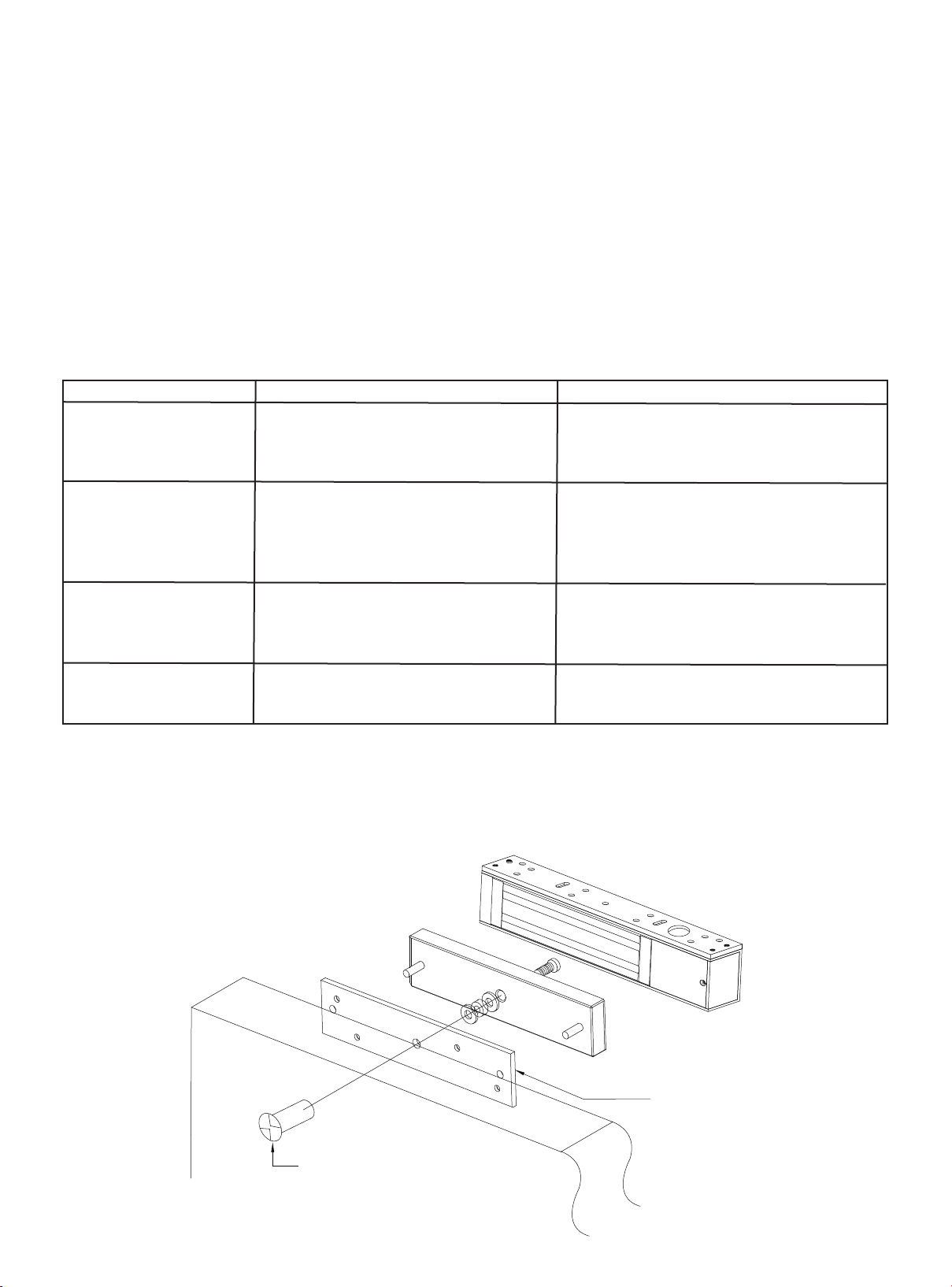
One way security dome nut
Door
Anti-Tamper-Plate
Important Safety Requirements
1. Apply thread-locker glue (i.g. Loctite) to the thread of the Armature-Plate-Fixing Screw (Allen-Screw) to
prevent from becoming loose.
2. Locks should be inspected at regular intervals to ascertain the safety functionality in conjunction with the
door environment.
3. The supplied Allen screws cater for maximum door-thickness of 45mm.

This manual suits for next models

3

Other FSH Lock manuals

FSH EcoLock HL1260 User manual

FSH

FSH EcoLock HL1260 User manual

FSH FCL0001 User manual

FSH

FSH FCL0001 User manual

FSH MEM2400LED User manual

FSH

FSH MEM2400LED User manual

FSH FEL990 Series User manual

FSH

FSH FEL990 Series User manual

FSH FES20 Series User manual

FSH

FSH FES20 Series User manual

FSH FEM5700 User manual

FSH

FSH FEM5700 User manual

Popular Lock manuals by other brands

Onguard 5514 user guide

Onguard

Onguard 5514 user guide

National Cabinet Lock C8178 Dimensional drawing

National Cabinet Lock

National Cabinet Lock C8178 Dimensional drawing

SECO-LARM E-941SA-300RQ manual

SECO-LARM

SECO-LARM E-941SA-300RQ manual

Falcon MA12 Series installation instructions

Falcon

Falcon MA12 Series installation instructions

schmersal AZM201Z-CC-T-1P2PW-A-2719-1 Instructions for operation

schmersal

schmersal AZM201Z-CC-T-1P2PW-A-2719-1 Instructions for operation

Von Duprin LGO installation instructions

Von Duprin

Von Duprin LGO installation instructions

tell NIAGARA quick guide

tell

tell NIAGARA quick guide

BMB Beschlaege NOKY SOLO P quick start guide

BMB Beschlaege

BMB Beschlaege NOKY SOLO P quick start guide

Scilox BL100 user manual

Scilox

Scilox BL100 user manual

Assa Abloy Securitron GL1 installation instructions

Assa Abloy

Assa Abloy Securitron GL1 installation instructions

Alarm Lock 4100 datasheet

Alarm Lock

Alarm Lock 4100 datasheet

VEVOR LFU4 user manual

VEVOR

VEVOR LFU4 user manual

Dorma Studio Classic Installation instruction

Dorma

Dorma Studio Classic Installation instruction

COMPX 1T-058 Information

COMPX

COMPX 1T-058 Information

Assa Abloy ASSA Coded 1.2 Programming instructions

Assa Abloy

Assa Abloy ASSA Coded 1.2 Programming instructions

COMPX MFW 29118 Dimensional drawing

COMPX

COMPX MFW 29118 Dimensional drawing

D&D Technologies Lokk-Latch PRO SL instructions

D&D Technologies

D&D Technologies Lokk-Latch PRO SL instructions

PacSafe prosafe 900 instructions

PacSafe

PacSafe prosafe 900 instructions

manuals.online logo
manuals.online logoBrands
  • About & Mission
  • Contact us
  • Privacy Policy
  • Terms and Conditions

Copyright 2025 Manuals.Online. All Rights Reserved.