3 Oct 2015
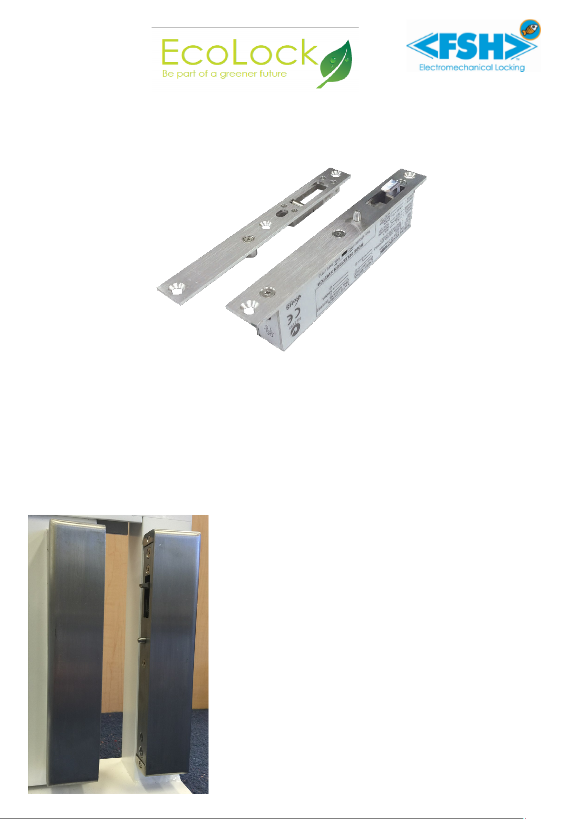
FSH HL1260 Installation Manual
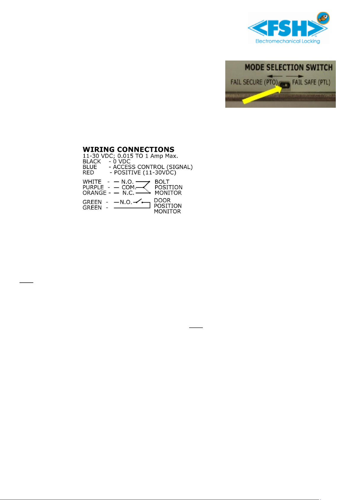
6. LOCKING MODE SETTING
The operation mode is set by a small changeover switch on the side of
the lock. The default setting from the factory is Power to Lock (Fail
Safe). If Power to Open (Fail Secure) is required, use the changeover
switch to set the Locking Mode.
CAUTION — THE SWITCH IS FRAGILE.
BROKEN SWITCHES ARE NOT COVERED BY WARRANTY.
If the lock has been powered up, it may be necessary to either remove
power to the lock for 5 minutes or cycle the lock once to ensure that the changeover has come into effect.
7. WIRING DIAGRAM
THREE WIRE CONTROL
RECOMMENDED FOR
POWER CONNECTION
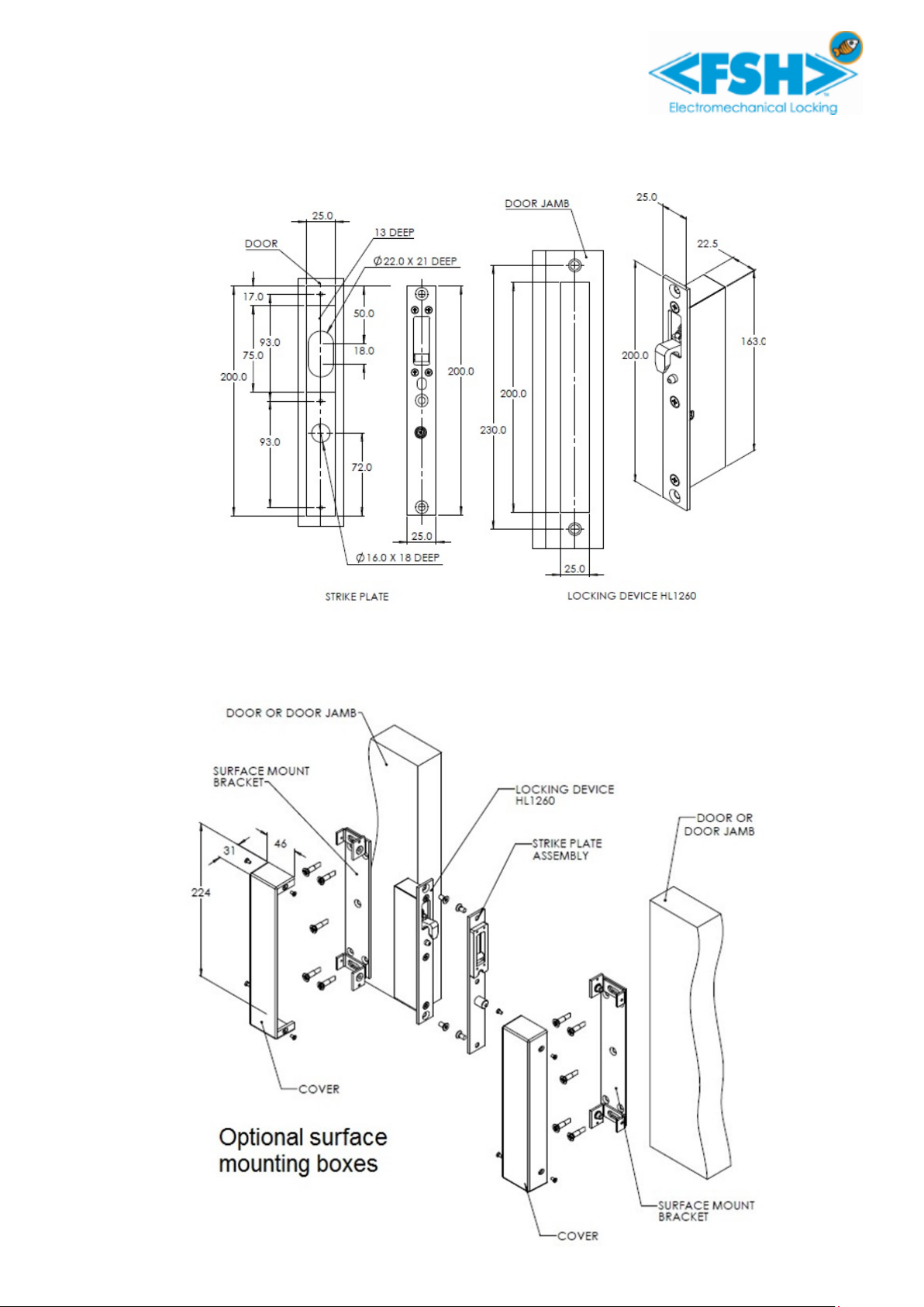
8. INSTALLATION
a. Door Frame and Door preparation detail for Locking Device and Strike Plate
Before commencing with the installation ensure the gap between door and frame is less than 4mm
•Mark out the edge of the door to accommodate the striking plate using the dimensional drawing corre-
sponding to centre line of Door
•Mark out the sliding door frame (usually a pocket) corresponding with the Door Frame
Note: Ensure both lock faceplate and striking plate will line up when the door is closed. The alignment pin on
the lock faceplate must line up with the corresponding hole on the strike plate both in a horizontal and
vertical plane.
Cut out a 22mm wide and 20mm deep cavity in the door behind the strike plate for the hook to be able to
fully engage.
Install the strike plate on the door, and lock in door frame. Ensure the door gap between the strike plate and
the faceplate on the locking device is not more than 4mm Note: Thickness of strike plate & faceplate = 3mm
b. Installation of Locking Device and Strike Plate
•Ensure all wiring connections are correct and insulated, with no wires contacting any sharp edges.
Install the locking device into the door frame and strike plate on door as shown above.
Connect the device and apply power, allow the door to open and close normally. When the door closes and
the magnet of the strike plate is line up within the locking range, the hook of the locking device will engage
within the strike plate and lock the door.
c. Adjustment of Door Position Reed Switch
To ensure the hook engages when the gap between the lock and the strike plate is less than 3mm a reed
switch is used. Different frame material may effect this sensing distance. In normal circumstances no adjust-
ment is required, however an adjustment screw in incorporated in the striking plate. Turning this screw
clockwise will reduce the detection gap between the door and frame, while an anticlockwise rotation will in-
crease the gap. The turning of the screw moves a magnet towards or away from the sensor in the lock. The
intention is to ensure the point of the hook does not hit the roller in the striking plate. The hook should pass
behind the roller with the “ramp” of the hook able to slightly pull in the door if necessary
d. Notes
Locking device must only be used in weather protected areas
Locking device requires a strike plate to operate. It also requires the strike plate to correctly align with the
lock faceplate•