Fujikura CT110 User manual

1st
Advanced Optical Fiber Cleaver
CT110/111
Instruction Manual
Thank you for purchasing Fujikura’s Advanced
Optical Fiber Cleaver.
Please read this instruction manual carefully
before operating the equipment.
Adhere to all safety instructions and
warnings contained in this manual.
Keep this manual in a safe place.
There may be updates without notice.

Please consent beforehand.
The software equipped in the cleaver and its related documents
are protected by copyright laws and international treaty
provisions as well as other intellectual property laws.
Copying some or all of instruction manual without notice is
forbidden.
Moreover, without permission from our company, it cannot be
used on the Copyright Act except when used as an individual.㻌
㻌

Table of Contentsᴾ
Safety Information...........................................................1
General Information........................................................4
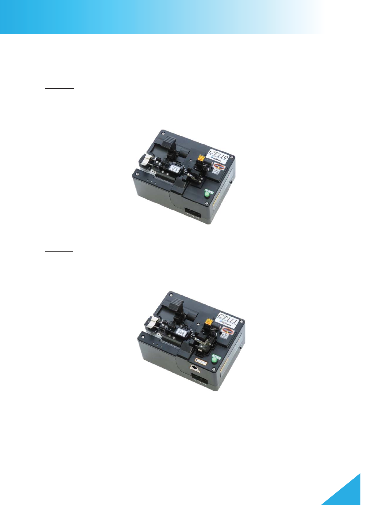
Introduction ......................................................................................................4
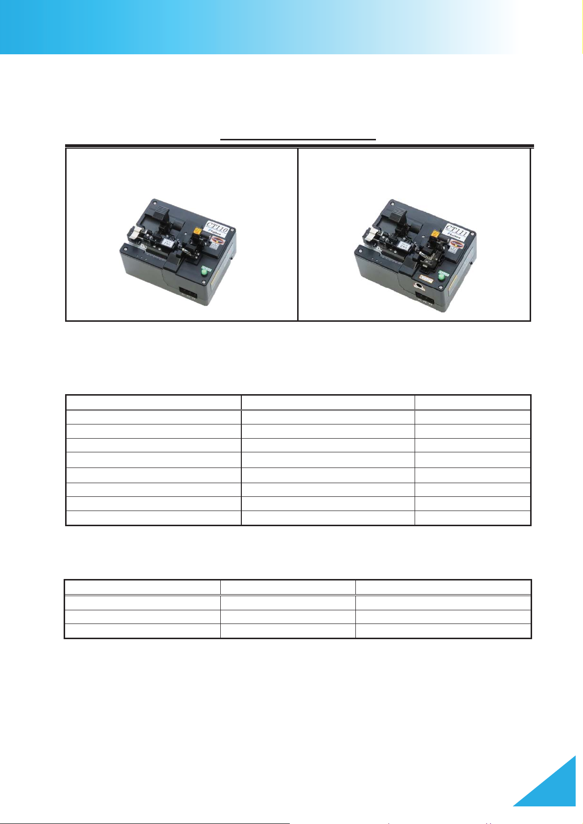
Components.....................................................................................................5
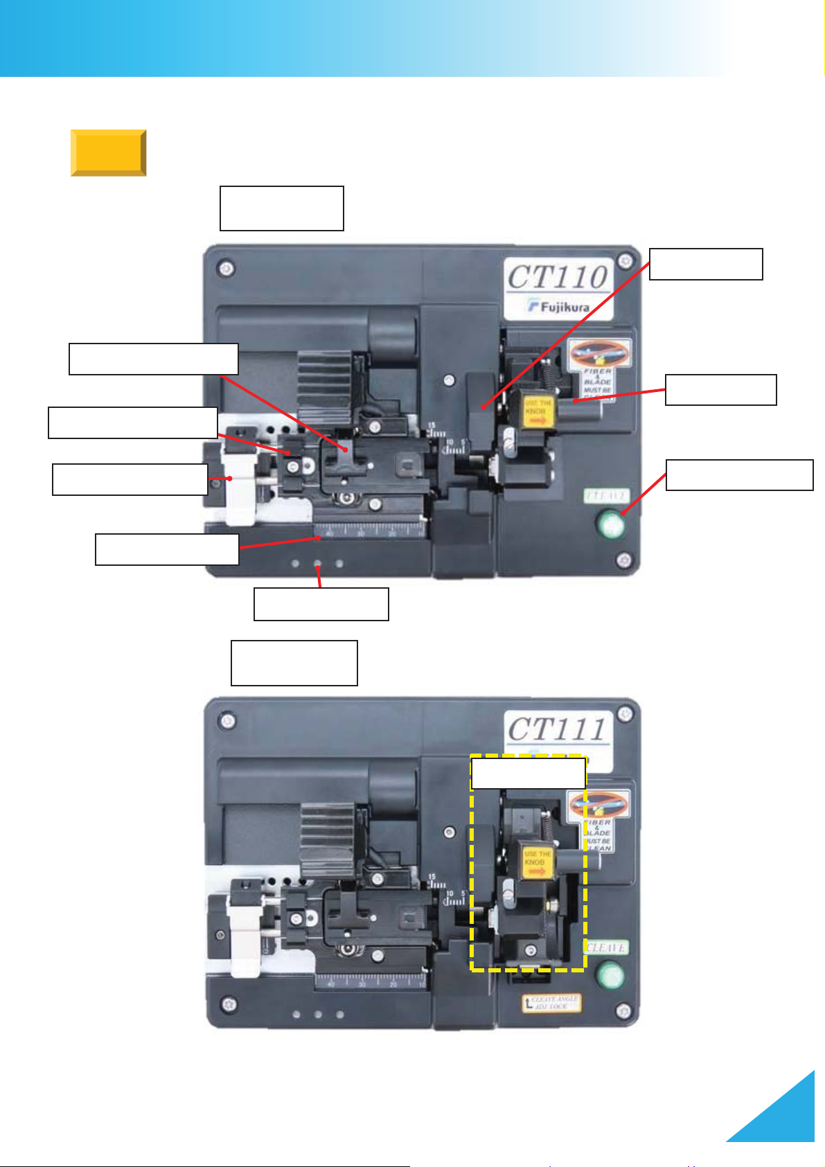
Description.......................................................................................................6
Cleaving Operation.........................................................9
Power Supply...................................................................................................9
How to Operate.............................................................................................. 11
Cleave Mode Selection ..................................................................................14
Adjusting the Total Fiber Length .....................................................................18
Using the Coating Adjuster.............................................................................21
Adjustment for Angled Cleaving (CT111 only) ................................................23
Settings.........................................................................25
Cleave Settings..............................................................................................25
Fiber Holder Registration (FH110 series only)................................................26
Other Settings ................................................................................................29
Blade Replacement........................................................................................30
Blade Adjustment ...........................................................................................32
Blade Position Change...................................................................................34
Cleave Count Display.....................................................................................35
LED Display Codes.......................................................36
Blade Position Display ...................................................................................36
Cleave Mode Display .....................................................................................37
Maintenace ...................................................................38
Cleaning the Cleaver......................................................................................38
Fiber Breakage Prevention.............................................................................39
Troubleshooting.............................................................40
Q & A .............................................................................................................40
Compliance...................................................................43
Warranty and Contact...................................................45
Warranty ........................................................................................................45
Contact Addresses .........................................................................................46

CT110/111_Rev1
11
Safety Information
Thank you for purchasing Fujikura’s Advanced Optical Fiber Cleaver
In this instruction manual, the processes and procedures are documented which should
be observed in order to use this product safely.
This cleaver has been designed for cleaving glass optical fibers. Cleaving should not be
attempted on anything other than a glass optical fiber with this product
Read and understand all safety
instructions.
Ask our service centers
for repair as soon as
possible.
Read this instruction manual carefully
before operating the machine.
Store this instruction manual in a safe
place.
The following symbols are used in this
instruction manual to indicate warning and
caution for safe use. Learn and
understand the meanings of these
symbols.
WARNING! / CAUTION!
There is a possibility of death, serious
injury, or physical loss if this indication is
ignored. Ignoring this indication is an
improper use of the machine.
PAY ATTENTION!
In general, a yellow triangle means the
associated caution should be observed.
Example:
PAY ATTENTION to hot surface!
DO NOT …!
Example:
DO NOT disassemble!
DO
A blue circle with a white graphic inside
means the associated process is required
for safe operation
Example:
You must disconnect the plug!
Follow all safety instructions
Stop using it when it malfunctions
Instruction Manual

CT110/111_Rev1
22
Safety Information
WARNING / CAUTION
Disconnect the AC power cord from the AC adapter plug or the wall outlet
immediately if a user observes the following:
• Fumes, bad smell, noise, or over-heat occurs.
• Liquid or foreign matter falls into this product.
• The Cleaver or AC adapter is damaged or dropped.
If any of these occur, contact our service center for repair. Leaving the
cleaver or AC adapter in a damaged state may cause equipment failure,
electric shock, or fire and may result in personal injury or death.
The AC adapter supplied with this product is the only adapter approved for
use with this product.
Using an improper AC power source may cause equipment damage,
fumes, electric shock, or fire and may result in personal injury or death.
Do not disassemble or modify the cleaver or the AC adapter in any way.
In particular, do not remove or bypass any electrical or mechanical device
(e.g. a fuse or safety switch) incorporated into the design and
manufacturing of this equipment. Modificatio
n could cause damage that
may result in electric shock, fire, personal injury, or death,.
Connect AC power cord properly to the AC Adapter and to the wall outlet.
When inserting the AC plug, make sure there is no dust or dirt on the
terminals. Insert the female plug into the AC
Adapter and the male plug
into the wall outlet until both plugs are fully seated. Incomplete
engagement may cause fuming, electric shock, equipment damage, or fire
and may result in personal injury or death.
Disconnect the AC power cord
when the cleaver is not being used.
Use the supplied AC power cord. Do not place heavy objects on the AC
power cord. Use of an improper or damaged cord may cause equipment
failure, electric shock, or fire and may result in personal injury or death.
Do not touch the cleaver, AC power cord and AC plugs with wet hands.
This may result in electric shock.
Do not operate the cleaver near hot objects, in hot environments, in dusty
/ humid environments, or when water condensation is present on the unit.
This may result in electric shock, cleaver malfunction, or poor cleaving
performance. When water condensation is present, leave the cleaver
powered off and allow to air-dry at room temperature for at least 24 hours.

CT110/111_Rev1
33
Safety Information
ᴾ
WARNING / CAUTION
Do not store the cleaver in any place where temperature and/or humidity are
extremely high. Such environments may cause damage to the cleaver.
Do not place the cleaver in an unstable or unbalanced position. The cleaver
may shift or lose balance, causing it to
fall. This may result in personal injury or
equipment damage.
The cleaver is a precisely adjusted and aligned instrument. Keep the unit away
from strong mechanical shock or impact. Failure to do so will result in
misalignent and lead to poor cleaving results. Use the supplied box for
transportation and storage. The box will protect the cleaver from damage,
moisture, vibration, and shock during storage and transportation.
Always set the cleaver blade to the correct position in the machine. Setting the
blade to an incorrect position may cause serious damage to the machine.
If the cleaver blade is replaced, only use the manufacturer-specified part.
Failure to do so will result in serious damage to the machine.
The cleaver requires no lubrication. Adding oil or grease may degrade the
cleaving performance and damage the cleaver.
This equipment must be repaired or adjusted by a qualified technician or
engineer. Incorrect repair may cause fire or electric shock. Please contact the
authorized distributor if any problems occur on the machine.
Keep the cleaver free of contaminants. They will degrade the cleave quality
and may cause the machine to malfunction.
Do not use the cleaver for anything other than cleaving optical
fibers. Using it
for any other purpose may damage the cleaver.
RECYCLING and DISPOSAL
In European Union
In accordance with the European Parliament Directive, electrical parts and materials
that can be re-used and/or recycled have been
identified in order that the use of new
resources and the amount of waste going for landfill can be minimised.
In the European Union, do not discard this product as unsorted municipal waste.
Contact your local authorities for further information.
In other countries
[Recycling]
To recycle this product, disassemble it first, sort each part separately by material
components and follow your local recycling regulations.
[Disposal]
This product can be disposed of same as the
standard electric poroducts. Follow your
local disposal regulations.

CT110/111_Rev1
4
General Information
Introduction
The CT110 / CT111 cleavers are designed for use with a single optical fiber.
To master the CT110 and CT111, read this instruction manual prior to use.
CT110
The CT110 model is applicable for cleaving fibers having a cladding diameter of up to
250m. This model does not have the angled cleaving unit.
CT111
The CT111 model is applicable for cleaving fibers having a cladding diameter of up to
250m. Angled cleaving is possible using the rotation base.
FH110, FH-100, and FH-70* series fiber holder options are available for the CT110/111.
*Additional accessories required

CT110/111_Rev1
5
General Information
Components
The contents of the standard package are shown; please confirm all items are included.
Standard Components
Name
Item
Amount
AC Adapter
ADC-21
1pc
AC Cord
ACC-**
1pc
USB Cable
USB-01
1pc
Quick Reference Guide
QRG-11-E
1pc
1.5mm Hex Wrench
HEX-01
1pc
2.5mm Hex Wrench
HEX-02
1pc
Cleave test report
CR-CT110
1pc
Warning and Cautions
WAC-06-E
1pc
Additional Options
Name
Item
Remarks
Cleaver Blade
CB-06A
Replacement blade
Fiber Holder Adapter Plate
AD-CT110-FH70
Fiber Holder Adapter for FH-70
Fiber Holder
FH110-***
Each Sizes
Advanced Fiber Cleaver
CT110
(without angle cleaving base)
CT111
(with angle cleaving base)

CT110/111_Rev1
6
General Information
Description
Clamp Unit
Fiber Holder Clamp
LED Indicators
Blade Unit
Rotary Base
CT111
Cleave Button
Top
CT110
Length Scale
Positioning Spacer
Coating Adjuster

CT110/111_Rev1
7
General Information
Left Lever
Right Lever
Fiber Clamp
Cleave Angle Adjustment Screw
(CT111 only)
USB Port
ON/OFF Switch
Holder Clamp
DC Power Port
Angle Scale
(CT111 only)
Function Keys
Battery Box Cover

CT110/111_Rev1
8
General Information
The device states can be confirmed using the Function keys and the LED Indicators.
Name
Description
Cleave
Button
Starts the cleaving
operation.
F1 key
Display
s the current blade position.
Hold the
F1 key to enter “blade position change” mode.
F2 key
Displays the current cleave mode.
Hold the F2 key to enter “cleave mode selection” mode.
F3 key
-
LED Indicators
Function Key Area
Cleave Button
F1 key
F2 key
F3 key
Function Keys

CT110/111_Rev1
9
Cleaving Operation
Power Supply
AC adapter
1. Only use a genuine Fujikura AC adapter and AC power cord.
2. Plug the AC cord into the wall and plug the cord into the AC port of the adapter block.
3. Plug the adapter cord into the DC power port of the cleaver.
Battery
1. Remove the battery box cover from the left side of the device.
2. Install 4 AA batteries into the battery carrier, observing polarity.
3. Insert the battery carrier into the device with the label facing outward.
4. Secure the battery box cover.
¾Both alkaline and Ni-MH rechargeable batteries may be used.
¾Remove batteries during transportation, storage,
or when the unit is not used
for an extended period of time.
Connect the
ACC-## to wall
outlet and ADC-21
to Cleaver
ADC-21
Remove the Battery Box Cover
Label facing out

CT110/111_Rev1
10
Cleaving Operation
Power ON/OFF
ᴾ
1. Remove any fiber before powering on the cleaver.
2. Slide the power switch to ON.

CT110/111_Rev1
11
Positioning Spacer
Cleaving Operation
How to Operate
Before cleaving, select an appropriate cleave mode. The 125m cleave mode is selected
from the factory.
ؕஜદ˺
Cleave the fiber (with fiber holder)
1. Load the fiber into the Fiber Holder, then strip and clean the fiber.
2. Confirm electrical power is supplied and fully release the Right-hand lever.
The fiber clamp unit will move to its home position.
䈜The fiber clamp unit will not move if it is already in its home position.
3. Fully release the Left-hand lever and set the fiber holder in place on the guide pins of
the fiber holder plate.
Functions of the Positioning Spacer
䐟Provides a consistent total fiber length after cleaving by maintaining constant
pressure toward the blade.
䐠After releasing the Left-hand lever, it can prevent the fiber holder from being picked
up by the clamp pad.
Fiber Holder
Plungers provide constant
forward pressure
Clamp Unit moves
Release the left and right levers

CT110/111_Rev1
12
Cleaving Operation
4. Close the Left-hand clamp to secure the Fiber Holder.
䈜If the Fiber Holder can provide enough clamping force to hold the fiber at the
cleaving tension, the left-hand fiber holder clamp is not necessary.
5. Close the right-hand lever to clamp the optical fiber.
6. For angled cleaving, rotate the angled cleaving base counterclockwise to twist the optical
fiber.
If the total fiber length after cleaving is 12mm,
the stripping length must be greater than
27mm.
The stripped portion of the optical fiber
must fully extend over the V-groove.
Cleave Button
Fiber Clamp
Rotate the Angled Cleaving Base counterclockwise
for angled cleaving. (CT111 only)
Clamp the optical fiber
with the right clamp.
Fiber Holder Clamp

CT110/111_Rev1
13
Cleaving Operation
7. Press the [CLEAVE] button to cleave the fiber.
During the cleaving operation, LEDs will be displayed as shown in the table below.
8. After cleaving is complete, open the left-hand lever and remove the fiber holder.
9. If the rotary base is engaged (CT111), return to parallel.
10. Open the right-hand lever and dispose of the optical fiber waste.
When the right-hand lever is opened, the clamp unit will return to its home position.
If repeating the cleave operation, return to step 3.
Applicable fiber
㻌
Applicable cladding dia.
80 to 250m
Applicable coating dia.
81 to 2000m
Fiber length
Total fiber length䠖11mm to 44mm
Cleave length䠖3mm to 44mm
LED 1 LED 2 LED 3
LED display
LED 2 is lit green:
C
leaving.
LED 2 is flashing green:
Cleaving
successful.
LED2 is flashing red:
Cleaving error.

CT110/111_Rev1
14
Example:
Cleaving Operation
Cleave Mode Selection
Selecting a Cleave Mode
80m, 125mand250m cleave modes are installed from the factory by default. It’s
possible to switch between the three primary cleave modes with the following steps:
1. Hold the F2 key to enter the cleave mode selection state. The current cleave mode will
be displayed as shown the table below.
2. While the LED is lit green, select the cleave mode from either F1 : 80m cleave mode,
F2 : 125m cleave mode or F3 : 250m cleave mode by pressing the applicable “F-key.”
Within this device, different cleave modes can be added and edited using the Data
Connection PC software. Refer to [Cleave Settings].
㻌
LED 1 LED 2 LED 3
LED display
LED 1 is lit green:
80m
cleave mode is selected.
LED 2 is lit green:
125m
cleave mode is selected.
LED 3 is lit green:
250m
cleave mode is selected.
LED 1 LED 2 LED 3
LED display
LED 1 flashes green 3 times:
80m
cleave mode is selected.
LED 2 flashes green 3 times:
125m
cleave mode is selected.
LED 3 flashes green 3 times:
250m
cleave mode is selected.
80m
125m
250m
Hold F2 key
When F1, F2, or F3 is pressed at
this stage, the corresponding LED
will blink 3 times to confirm the
chosen cleave mode has been
selected

CT110/111_Rev1
15
Cleaving Operation
Fiber Holders
ᴾ
The CT110/111 can be used with 3 types of fiber holders. Each fiber holder requires the
fiber holder base to be set up accordingly.
Adjusting the Position Spacer
Each fiber holder type requires the user to adjust the positioning spacer. The
positioning spacer has two placement options - adjust as shown below.
When 250m cladding diameter fiber is cleaved, the fiber holder must be loaded
backward into the FSM-100M/P. The positioning spacer and the coating adjuster need
to be removed when the fiber holder is loaded backward. In this case, fiber holder
management cannot be used.
Remove
Positioning Spacer
Fiber Holder Adapter for FH-70
AD-CT110-FH70
FH110
FH-100
FH-70
Additional accessory
required
Compatible Fiber Holders:
FH110
FH-100
H
110
FH
-
1
0
0
:
Loosen the screws
Rear position
HEX-01
1.5mm Hex Wrench
Forward position

CT110/111_Rev1
16
Cleaving Operation
Fiber Holder Management (FH110 series only)
Cleave modes can be assigned to each individual FH110 fiber holder. If a cleave mode
is assigned to a FH110 fiber holder, the cleaver can be set to detect the fiber holder
and retrieve the assigned cleave mode.
For more information about registering with FH110 fiber holders, refer to the [Fiber
Holder Registration] section.
¾Fiber holder management is unavailable when using
battery power.

CT110/111_Rev1
17
Cleaving Operation
Replacing the Fiber Holder Adapter
FH-70 series fiber holders can be used after replacing the factory fiber holder adapter
with the FH-70 Series Fiber Holder Adapter.
AD-CT110-FH70
Fiber Holder Adapter for FH-70
FH-70
HEX-01
1.5mm Hex wrench
Loosen the screw, then remove
the Fiber Holder Adapter.
Attach the Fiber Holder Adapter
for FH-70.
This manual suits for next models
1
Table of contents
Other Fujikura Tools manuals
Popular Tools manuals by other brands

Industrial Fiber Optics
Industrial Fiber Optics IF-TK4 operating instructions

Holman
Holman 40233 installation guide

AG SHIELD
AG SHIELD 12" CROSS AUGER Operator's manual

Black & Decker
Black & Decker EXTENDER ATM100 instruction manual

RODCRAFT
RODCRAFT RC5305 Operator's manual

oneup
oneup EDC LITE Install instructions