List of Figures
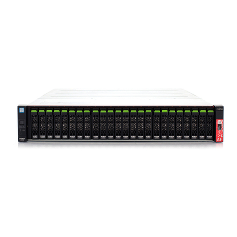
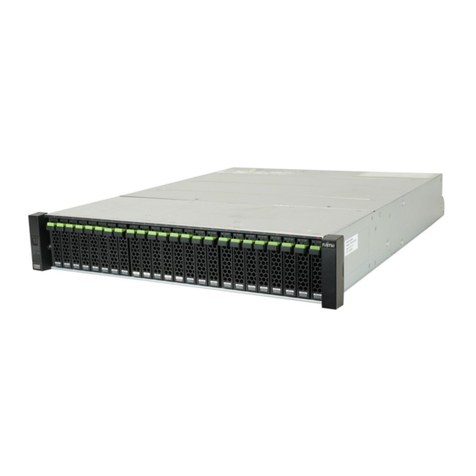
Figure 1.1 Front View of a 2.5" Type Controller Enclosure...........................................................................................18
Figure 1.2 Front View of a 3.5" Type Controller Enclosure...........................................................................................19
Figure 1.3 Rear Views of a Controller Enclosure (When Only One Controller is Installed) ...........................................19
Figure 1.4 Rear Views of a Controller Enclosure (When Two Controllers are Installed) ...............................................20
Figure 1.5 Front View of a 2.5" Type Drive Enclosure..................................................................................................21
Figure 1.6 Front View of a 3.5" Type Drive Enclosure..................................................................................................21
Figure 1.7 Front View of a High-density Drive Enclosure ............................................................................................22
Figure 1.8 Rear Views of a Drive Enclosure (When Only One I/O Module is Installed).................................................22
Figure 1.9 Rear Views of a Drive Enclosure (When Two I/O Modules are Installed).....................................................23
Figure 1.10 Rear Views of a High-density Drive Enclosure............................................................................................23
Figure 1.11 Power distribution unit for DX100 S3/DX200 S3 (AC200-240V, 1U 4Outlets) .............................................24
Figure 1.12 Power distribution unit for DX100 S3/DX200 S3 (AC200-240V, 2U, 12Outlets) ..........................................24
Figure 1.13 Power distribution unit for DX100 S3/DX200 S3 (AC200-240V, 2U, 16Outlets) ..........................................25
Figure 3.1 System Configuration Example..................................................................................................................44
Figure 3.2 Network Setting Label...............................................................................................................................51
Figure 4.1 Connecting Cables Between Enclosures (When Only One Controller is Installed) ......................................56
Figure 4.2 Connecting Cables Between Enclosures (When Two Controllers are Installed) ..........................................56
Figure 5.1 Example of Differential Backup Settings with SnapOPC+...........................................................................71
Figure 5.2 Example of Creating Operation Volume and Backup Volume ....................................................................72
Figure 5.3 PC Terminal Connection for Initial Setup ...................................................................................................73
Figure 5.4 ON Position (Marked "|") of the Main Line Switches on a 1U Power Distribution Unit ...............................73
Figure 5.5 ON Position (Marked "|") of the Main Line Switches on a 2U Power Distribution Unit ...............................74
Figure 5.6 ON Position (Marked "|") of the PSU Switch on a Power Supply Unit .........................................................74
Figure 5.7 RAID Group Creation..................................................................................................................................88
Figure 5.8 RAID Group Information After Creation......................................................................................................91
Figure 5.9 Operation Volume Creation .......................................................................................................................92
Figure 5.10 Generation Management Volume (SDV) Creation .....................................................................................94
Figure 5.11 Temporary Work Volume (SDPV) Creation .................................................................................................95
Figure 5.12 Volume Information After Creation............................................................................................................97
Figure 8.1 Connection Configuration with Servers....................................................................................................135
Figure 11.1 Solution — Continuous Business...............................................................................................................174
Figure 11.2 Solution — Performance/Tuning ...............................................................................................................176
Figure 11.3 Solution — Green......................................................................................................................................178
Figure 11.4 Solution — Cloud Platform (Oracle VM Linkage).......................................................................................180
Figure 11.5 Solution — Cloud Platform (VMware Linkage)..........................................................................................181
Figure 11.6 Solution — Cloud Platform (Microsoft Linkage) ........................................................................................183
16
FUJITSU Storage ETERNUS DX100 S3/DX200 S3 Disk storage system Configuration Guide (Basic)
Copyright 2014 FUJITSU LIMITED
P3AM-7652-02ENZ0