Furman PB-48 User manual

Owners Manual
MODELS PB-48, PB-48D
0103 960119-2177
Patch Bay
System

PB-48 PATCH BAY SYSTEM
2

PB-48 PATCH BAY SYSTEM 3
Introduction
Thank you for your purchase of a Furman PB-48 or PB-48D Patch Bay You
now own a versatile, rugged, high quality accessory that will make your entire
audio system easier to operate Your new PB-48 is ready to use right out of the
box But please take a few moments now to read these instructions to be sure of
getting the best results Youll learn about the PB-48's capabilities, you will under-
stand patch bay terminology and youll have the answers to questions that arise
when you are using a patch bay for the first time
Your PB-48 patch bay is designed to serve as a hub where all audio lines in
your audio system come physically close together The PB-48 makes it possible
for you to quickly and easily set up any system configuration from one convenient
central location Of course, you could wire a system without a patch bay But the
great advantage of a patch bay comes when you want the flexibility to configure
your audio system differently from the way you originally set it up
To reconfigure your system without a patch bay, you would have to reach around
to the back of various pieces of equipment to unplug and replug a number of
cables, all the while trying to remember how it was before so you can put it back
together when you are done with the special setup After going through this a few
times, you would almost certainly find that the cables in back of your equipment
are tangled up in knots A patch bay eliminates this problem while making your
system much more flexible and easier to use
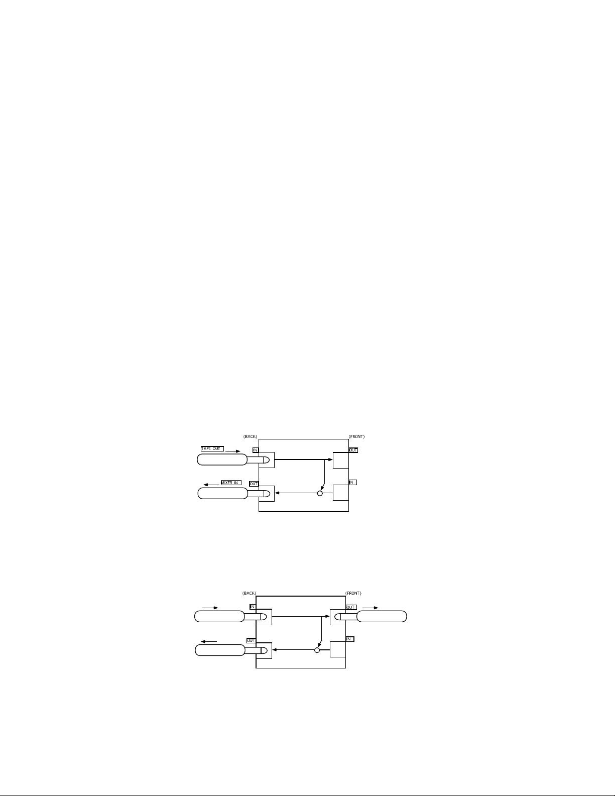
For example, in a studio, a tape recorders outputs may normally be connected
to the mixing board for playback But at the end of a session, you may want them
to be connected directly to another recorder to make dupes You dont want to find
yourself replugging cables on your hands and knees A well-designed patch bay
system eliminates this frustration, since it will allow you to make easily traceable
patch changes, then return the system to your original setup in a flash
Patch Bay Terminology
Model PB-48 has forty-eight 1/4 jacks both in front and rear Each vertical pair
of patch points is mounted on its own circuit board, which holds two front panel
and two rear panel jacks The upper rear row of jacks always connects to outputs
of equipment, while the lower rear row always connects to inputs of equipment
The basic signal flow is in the upper rear jack and out the lower rear jack Along
the way the signal passes through the front panel jacks of your PB-48 The jacks
used are high quality TRS (tip-ring-sleeve) jacks with self-cleaning contacts Be-
cause TRS jacks have three, not two, conductors, they allow for the use of either
balanced or unbalanced circuits
Model PB-48D, which substitutes six 25-pin D-Sub connectors on the rear for
phone jacks to make interconnection with recording devices quicker and neater, is
constructed slightly differently It uses a single horizontal circuit board with all com-
ponents mounted on it This construction is better suited to the use of multi-pin
connectors

PB-48 PATCH BAY SYSTEM
4
A patch bays jacks can be configured in four ways: Full-Normalled, Half-
Normalled, Non-Normalled and Multed
Both the PB-48 and PB-48D are shipped as half-normalled patch bays That
means each of their 24 vertical jack pairs are factory-set so the upper rear jack is
normally connected to the lower rear jack The signal flow through the jacks on
the front panel is such that inserting a plug in the top jack on the front does not
break the normal connection between the rear panel jacks, but provides a tap on
its circuit to send a signal to two devices simultaneously However, inserting a plug
into the lower front jack does break the signal flow, allowing the insertion of a
device, such as a signal processor, into the loop
Half Normalled
As mentioned above, each vertical pair of upper and lower jacks on the PB-
48s rear panel is connected internally, and the signal flows through both of them
The original setup of your equipment is retained, in that two devices are connected
without the use of any front panel patch cords As shown in Figure 1, you can
connect one tape output to one of the PB-48s rear panel upper jacks, and connect
an input channel on a mixing board to the lower rear panel jack The signal will
flow from the tape output to the mixer input without requiring a patch cord All of
the rear panel jacks will function in this manner when there is no patch cord plugged
into the corresponding lower front panel jack Note: For simplicity, these diagrams
show mono plugs and jacks with only one normal link connecting a vertical pair,
but the jacks are actually TR types with two links. Two are needed to connect
both the tip and ring contacts, to allow the use of balanced lines. The switch in the
bottom front jack is a double-pole type which switches both links simultaneously.
In a half-normalled patch bay such as the PB-48, each lower front panel jack
has an internal switch When one end of a patch cord is inserted into the upper
front panel jack, the switch on the lower front panel jack remains closed, as shown
in Figure 2 The signal from the upper rear panel jack continues to flow to the lower
rear panel jack as it does in Figure 1, but it can also be simultaneously routed to
Figure 2
Figure 1

PB-48 PATCH BAY SYSTEM 5
another device via the upper front panel jack The upper front jack allows a signal
split, or mult, just as a Y-cord would do
When one end of a patch cord is inserted into the lower front panel jack, the
switch breaks the connection between the corresponding rear panel jacks, as
shown in Figure 3 This means that you can interrupt the signal that flows between
the upper and lower rear jacks, and re-route it to another destination with a patch
cord Using our earlier example of a mixer output connected via the rear panel to a
recorder input, with two patch cords you can insert a device, such as an equalizer,
between the mixer output and the recorder input
Non-Normalled
Non-normalling is the most common customization you may wish to make
to one or more of your PB-48's vertical pairs For example, if you have an equalizer
that is not part of the normal setup, it may be convenient to connect its input and
output to the same vertical pair (as shown in Examples 1 and 3 on page 6), but
without the input and output being connected together by the normal link (If such
a connection were allowed to exist in equipment that is idling, it could cause harm-
ful feedback or oscillation )
In a non-normalled pair, as shown in Figure 4 below, a front panel upper jack is
connected only to its corresponding rear panel upper jack, and the front panel
lower jack only to its corresponding rear panel lower jack, with no link between the
two To configure one or more jack pairs this way, please see Customizing on
page 7
ull-Normalled
In a Full-Normalled pair, both front panel jacks would have a switch, and plug-
ging a patch cord into either the upper or lower front panel jacks would interrupt
the signal between the corresponding rear panel jacks Full-normalled patch bays
are a relic of the past, and are rarely implemented nowadays because the mult
feature of the top front jack is lost, and no particular advantage is gained In any
case, because PB-48 modules do not have switching jacks in the top front posi-
tions, the full-normalled configuration is not possible
Figure 4
Figure 3

PB-48 PATCH BAY SYSTEM
6
xamples of Patches
Example 1 below illustrates a typical patchsay, inserting an outboard equal-
izer into track 7 Two patch cords are required Each connects an output jack on
the front panel upper row to an input jack on the front panel lower row (You never
have to plug both ends of a patch cord into the same vertical pair to connect them,
because the PB-48s normal internal wiring already does that for you )
Example 2 is a slightly different kind of patch Instead of inserting additional
equipment, it shows four tape outs routed to a different set of inputs than usual
This might be convenient for a mixdown, for example, to take advantage of better
EQ facilities in the main section of the board Of course, Aux 1-4 should be turned
down or muted to avoid confusion during mixing
In Example 3, one Effects Send channel on the board is split to take advantage
of two kinds of reverbs This illustrates that the PB-48 lets you split an output two
ways: one via the internal normal link, and the other via a patch cord This is the
characteristic that makes the PB-48 half-normalled
Example 1
Example 2
Example 3

PB-48 PATCH BAY SYSTEM 7
Customizing
Non-Normalling
As mentioned earlier, the most common customization you might want to make
is to defeat the normal links on one or more vertical pairs For example, it may be
convenient to connect the input and output of an equalizer that is not part of your
regular set-up to the same vertical pair, as shown in Examples 1 and 3 Without
customization, the effect of doing this would be that the input and output of the
equalizer would be shorted together via the normal link (except when the equalizer
was in use, in which case the plug in the bottom, input jack would break the link )
But some equipment may oscillate when the input and output are connected
together This could possibly lead to damage or interfering crosstalk There are
two ways to eliminate this problem The easiest way is to offset the input and
output of the equalizer, or other device Another method is to convert the vertical
pair to the non-normalled configuration, which eliminates the normal link Both
methods are explained here
Offsetting simply means that the devices front panel jacks are not part of the
same vertical pair, as shown in Example 4 below
Converting a pair to non-normalled is easy to do, but due to the different con-
struction of the PB-48 and the PB-48D, the method is different for each model
PB-48: Remove the front cover from the patch bay by pulling it forward If the
unit is installed in a rack, the cover may be removed without needing to dismount
the unit from the rack simply by removing only two of the four screws that secure it
in the rack Just remove the lower left and upper right screws, and the cover can
be pulled off To defeat the normal links on a particular module, flip it over, so that
the larger switching jack that was in the bottom front before, becomes top rear
The circuit board remains on the left side as viewed from the front Replace the
cover and re-install the two rack screws
PB-48D: If it is installed in a rack, the PB-48D must be removed to allow ac-
cess to the top surface However, it is not necessary to disassemble the unit The
normal linking is accomplished by means of suitcase jumper plugs When they
are in place, the links are intact When they are removed, a pair becomes non-
normalled You can reach the suitcase jumpers with a pair of long-nose pliers
inserted through the rectangular openings on top of the unit There are two for
each vertical pair, located directly behind the jacks Both must be pulled straight
up and off to convert the pair to non-normalled
Example 4

PB-48 PATCH BAY SYSTEM
8
After a pair of jumpers is removed, we recommend saving them for possible
later re-installation by storing them in place, but positioned so that each contacts
only one of the two pins Note: The proper positioning of the jumpers for standard,
half-normal operation is with the long dimension left-to-right Do not install them in
the front-to-back orientation
Multing
A group of jacks connected together is called a mult One of the PB-48s
unique features is that you can choose any number of jacks and wire them to-
gether to form a mult of any size, up to the entire 48 jacks of the patch bay (Note:
Multing is not possible with the PB-48D ) For example, as in Example 5, you could
connect four of the top front panel jacks together, and four of the lower front panel
jacks together to make two mults In this case the two sets of multed jacks are not
connected to each other top-to-bottom
Example 5 illustrates the use of a mult A patch cord connects Effects Send to
one of the group of four Mult 1 jacks This signal will now also be present at the
other three Mult 1 jacks These three are then patched to three different effects
processors The outputs of the three processors are patched to three input chan-
nels of the mixer, so you can creatively mix and pan them to achieve a unique
sound
To create mults of three or more jacks, remove the front cover as described
under Non-Normalling above and remove the modules that will comprise it Look
for unsoldered connection points on each modules circuit board labeled T for
tip, R for ring, and G for ground (sleeve) There are T and R points for both the
top and bottom jacks (The bottom T and R may or may not be labeled They are
located in a line directly under the G point ) The connection points are positioned
to allow easy wiring from one circuit board to adjacent boards Pass a bare, 22
gauge solid wire through each hole and solder it to the corresponding holes on
adjacent boards Note that the signal ground on each circuit board is isolated from
the chassis and from other circuit boards (to prevent ground loops), so the ground
must be wired along with the signal lines Therefore, five wires are used to link
together a group of modules intended to be a mult If these modules are turned
around (as described under Non-Normalling above) and nothing is plugged into
the rear jacks, there will result a single mult as wide as the number of modules
tied together, and encompassing both the top and bottom rows If you wish to
create separate mults in the top row and the bottom row (as in Example 5), it is not
necessary to turn the modules around, but you must cut the two traces comprising
the normal link between the top and bottom jacks on each module making up the
mults The proper places to cut can be identified as two very narrow traces just
below the upper T and R points Cut them cleanly with a sharp implement and curl
the cut ends back to make sure there is no chance of shorting
Example 5

PB-48 PATCH BAY SYSTEM 9
Installing the PB-48
The PB-48 is intended for mounting in a standard 19" equipment rack A logi-
cal spot to install it would be near the majority of the equipment to which it con-
nects, to minimize cable lengths Standard racks come equipped with mounting
rails with holes tapped for 10-32 machine screws Be sure to use only 10-32 screws
(in particular, avoid 10-24 screws, which will fit if forced but will strip the threads)
To avoid marring the panel when tightening the screws, use nylon washers under
the screw heads
Patch Cords
Furman supplies its Patch Bay users better quality, highly flexible patch cords
in six styles at extremely low prices They may be used for either front panel patch-
ing or rear panel interconnections The prices quoted below are for sets of ten
cords. Prices include UPS shipping to locations in the USA other than Alaska and
Hawaii You can order them directly from Furman by mail, or by phone or fax using
your Visa or MasterCard Our numbers are listed on the back cover of this booklet
Please call between 8:00 a m and 5:00 p m Pacific Time
PATCH-P 10 Patch Cords, 1/4" phone to 1/4" phone, 30 inch (75 cm) $15 95
PATCH-R 10 Patch Cords, RCA to RCA, 30 inch (75 cm)$15 95
PATCH-T 10 Patch Cords, TRS (stereo phone) to TRS,30 inch (75 cm) $19 95
PATCH-PP 10 Patch Cords, 1/4" phone to 1/4" phone, 72 inch (183 cm) $17 95
PATCH-PR 10 Patch Cords, 1/4" phone to RCA,72 inch (183 cm) $17 95
PATCH-RR 10 Patch Cords, RCA to RCA,72 inch (183 cm) $17 95
California residents must add 7 5% sales tax Add shipping charges (if Alaska,
Hawaii, or outside USA)allow 1 lb per set of 10
Limited Warranty
The Furman PB-48 and PB-48D are warranted against failures due to defec-
tive parts or faulty workmanship for a period of three years after delivery to the
original owner During this period, Furman will make any necessary repairs with-
out charge for parts or labor Shipping charges to the factory or repair station must
be prepaid by the owner; return shipping charges (via UPS Ground) will be paid by
Furman
This warranty applies only to the original owner and is not transferable Also, it
does not apply to repairs done other than by the Furman factory or Authorized
Repair Stations

PB-48 PATCH BAY SYSTEM
10
This warranty shall be cancelable by Furman at its sole discretion if the PB-48
or PB-48D unit has been subjected to physical abuse or has been modified in any
way without written authorization from Furman Furmans liability under this war-
ranty is limited to repair or replacement of the defective unit
Furman will not be responsible for incidental or consequential damages re-
sulting from the use or misuse of its products Some states do not allow the exclu-
sion of incidental or consequential damages, so the above limitations may not
apply to you This warranty gives you specific legal rights, and you may also have
other rights which vary from state to state Warranty claims should be accompa-
nied by a copy of the original purchase invoice showing the purchase date (if a
Warranty Registration Card was mailed in at the time of purchase, this is not
necessary) Before returning any equipment for repair, please read the important
information on service below
Service
Before returning any equipment for repair, please be sure that it is adequately
packed and cushioned against damage in shipment, and that it is insured We
suggest that you save the original packaging and use it to ship the product for
servicing Also, please enclose a note giving your name, address, phone number
and a description of the problem
NOTE: All equipment being returned for repair must have a Return Authoriza-
tion (RA) Number To get an RA Number, please call the Furman Service Depart-
ment, (707) 763-1010, Ext 40, between 8 am and 5 pm U S Pacific Time Please
display your RA Number prominently on the front of all packages

PB-48 PATCH BAY SYSTEM 11

PB-48 PATCH BAY SYSTEM
12
Furman Sound, Inc.
1997 South McDowell Blvd.
Petaluma, California 94954-6919
Phone: (707) 763-1010
Fax: (707) 763-1310
www.furmansound.com
-mail: [email protected]
PB-48D Schematic Diagram
1 vertical pair shown, typical of all 24
Other manuals for PB-48
2
This manual suits for next models
1
Table of contents
Other Furman Conference System manuals
Popular Conference System manuals by other brands

Panasonic
Panasonic KX-VC1300 user manual

Spracht
Spracht Aura Mobile BT user guide

Rath
Rath Command Center Installation & operation manual

COMMUNICATIONS-APPLIED TECHNOLOGY
COMMUNICATIONS-APPLIED TECHNOLOGY ICRI/2P Setup and operating procedures

Polycom
Polycom VSX 5000 instruction manual

AT&T
AT&T SPIRIT 308 Product information guide