Furuno FAR-2318 User manual

EQUIPMENT LISTS
xxiv
radar’s specification. Refer to the following table to confirm your category. The radar category de-
pends on the installed monitor.
For BB type, a monitor unit meeting the category requirements of IMO must be prepared by the
user.
Category Radar type ANT. rotation speed
CAT 1 FAR-2318, FAR-2328, FAR-2328W, FAR-2338S,
FAR-2338SW, FAR-2338-NXT
24 rpm
CAT 1H Same models as above 42 rpm
CAT 2 FAR-2218, FAR-2228, FAR-2238S, FAR-2238S-NXT 24 rpm
CAT 2H Same models as above 42 rpm
CAT 3 FAR-2218, FAR-2228, FAR-2238S,
FAR-2238S-NXT
24 rpm

1-1
1. INSTALLATION
1.1 Antenna Unit (X-band Radar)
1.1.1 Installation Considerations
• The Antenna Unit is generally installed either on top of the wheelhouse or on the
radar mast, on a suitable platform. Locate the Antenna Unit in an elevated position
to permit maximum target visibility.
• A line of sight from the Antenna Unit to the bow of the ship must hit the surface of
the sea in not more than 500 m or twice the ship’s length, depending whichever val-
ue is smaller, for all load and trim conditions.
• BS/CS broadcast equipment may be subject to interference from radar waves. For
BS/CS antenna installation, adjust the height and installation position of the BS/CS
antenna to avoid interference from radars.
• Install the Antenna Unit so that any blind sectors caused by objects (mast, etc.) are
kept to a minimum. A blind sector must not exist in arc of the horizon from right
ahead to 22.5° aft of the beam to either side (see the figure below). Also, individual
blind sectors of more than 5°, or the total arc of both blind sectors of more than 20°,
must not occur in the remaining arc (Figure 2). Note that any two blind sectors sep-
arated by 3° or less are regarded as one sector.
• Do not install the antenna where extreme winds may strike the port and starboard
sides of the antenna.
NOTICE
Do not apply paint, anti-corrosive sealant or contact
spray to coating or plastic parts of the equipment.
Those items contain organic solvents that can damage
coating and plastic parts, especially plastic connectors.
less than 500 m or twice the ship's length
Figure 1 Figure 2
less than 3°
22.5°
22.5°
270° 90°
a, b, c: less than 5° respectively
a+b+c+: less than 20°
a, b, c: less than 5° respectively
a+b+c+: less than 20°

1. INSTALLATION
1-2
• Install the Antenna Unit away from interfering high-power energy sources and TX
radio antennas.
• Keep the lower edge of the Antenna Unit above the safety rail by at least 500 mm.
• Install two Antenna Units as shown in the figure below.
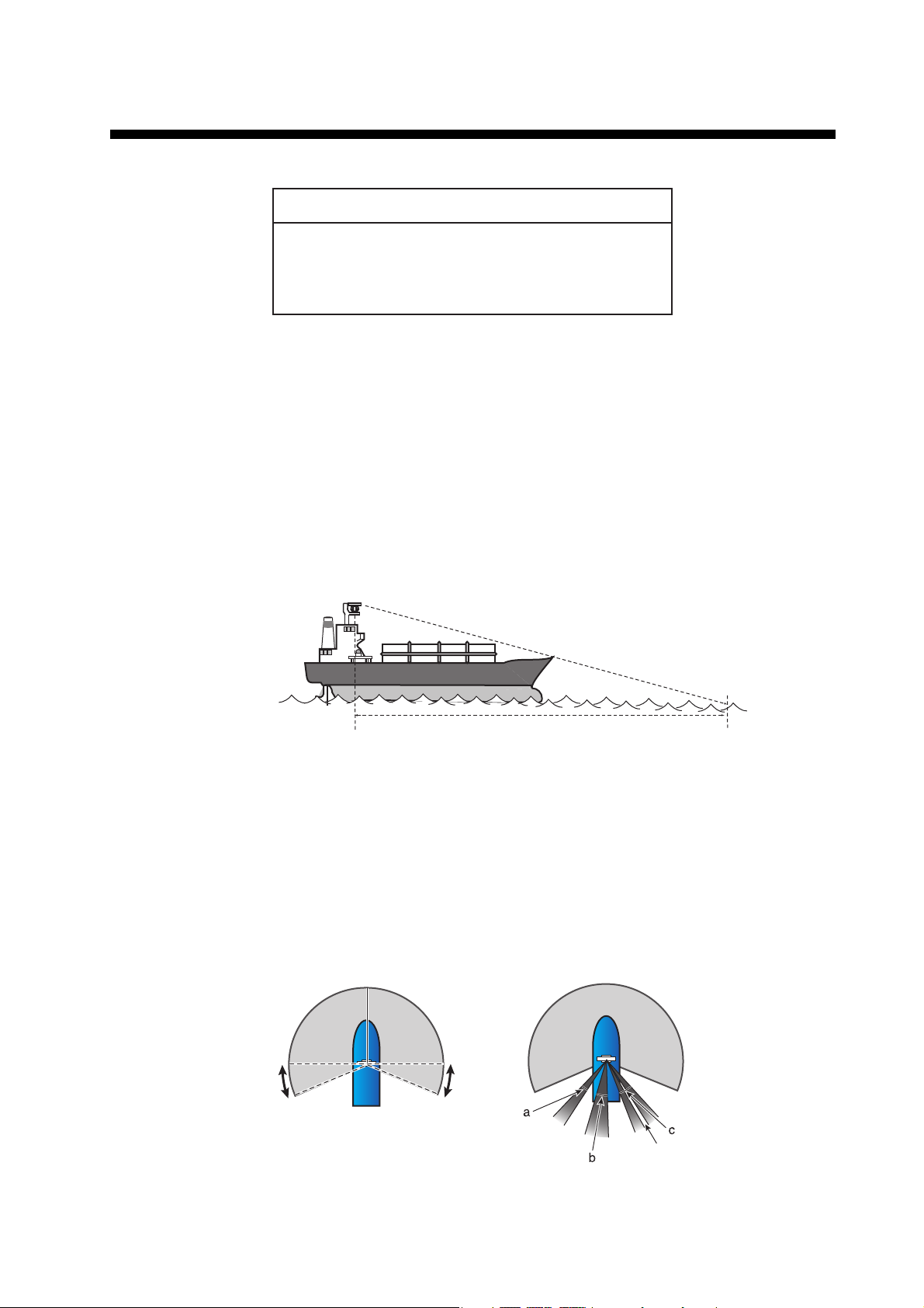
• No funnel, mast or derrick shall be within the vertical beamwidth of the Antenna Unit
in the bow direction, especially zero degree ±5°, to prevent blind sectors and false
echoes on the radar picture.
• It is rarely possible to place the Antenna Unit where a completely clear view in all
directions is available. Therefore, determine the angular width and relative bearing
of any shadow sectors for their influence on the radar at the first opportunity after
fitting.
• Locate the antenna of an EPFS clear of the radar antenna to prevent interference
to the EPFS. A separation of more than two meters is recommended.
• A magnetic compass will be affected if the Antenna Unit is placed too close to the
compass. Observe the compass safe distances on page ii to prevent interference
to a magnetic compass.
• Do not paint the radiator aperture, to ensure proper emission of the radar waves.
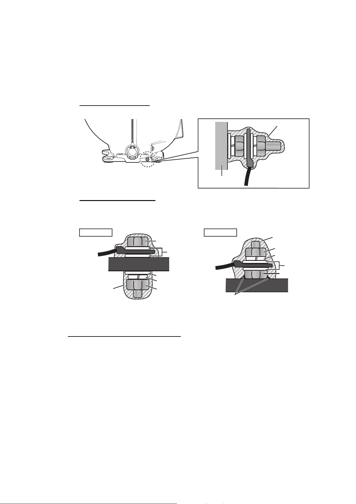
• Ground the unit with the ground wire (supplied).
• Deposits and fumes from a funnel or other exhaust vent can affect the aerial perfor-
mance and hot gases may distort the radiator portion. Do not install the Antenna
Unit where the temperature is more than 55 °C.
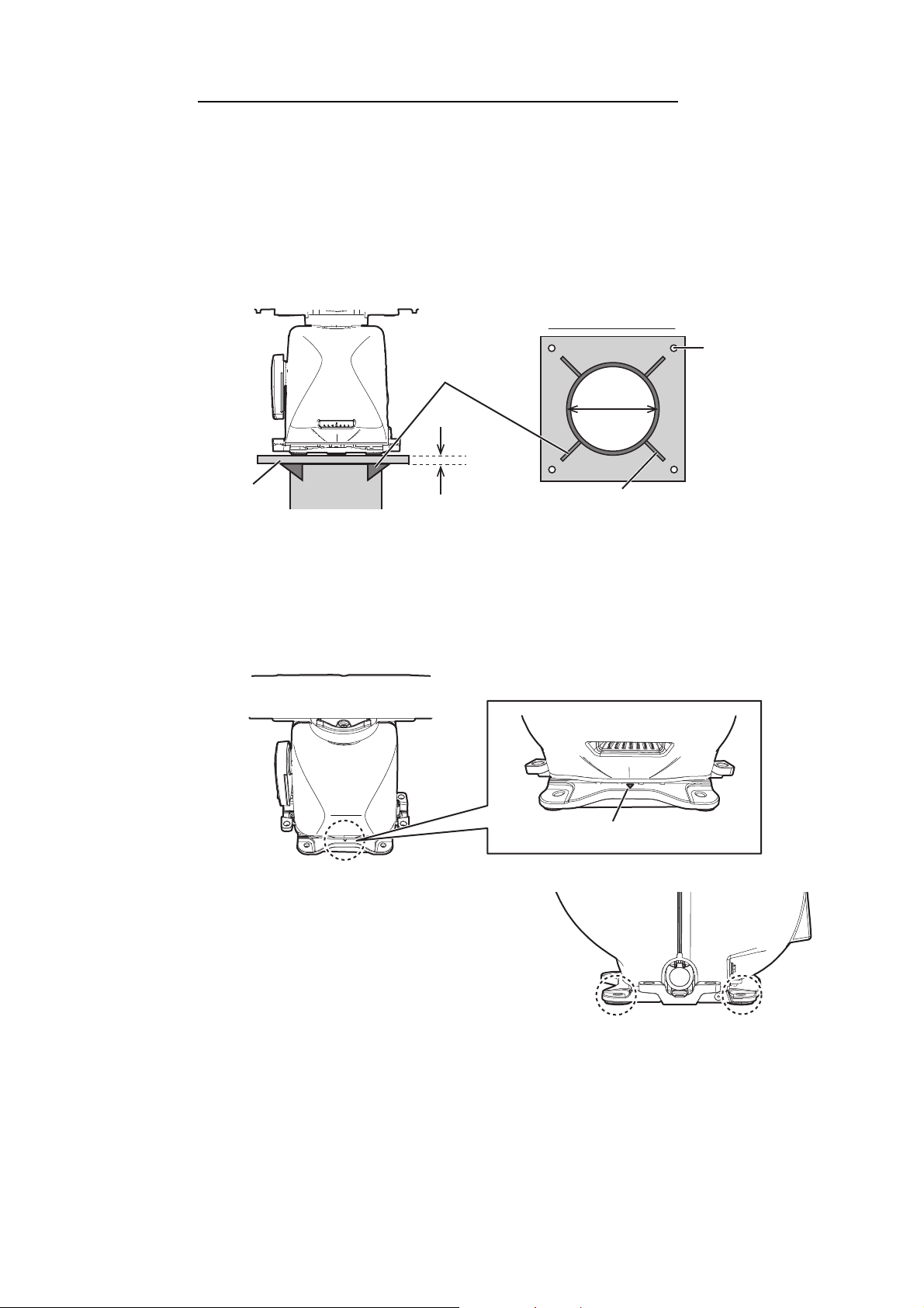
• Leave sufficient space around the unit for maintenance and servicing. See the An-
tenna Unit outline drawing for recommended maintenance space.
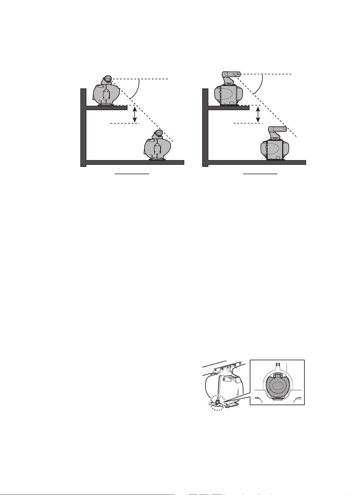
• For X-band radar, an antenna switch is pro-
vided on the chassis to stop the antenna.
Make sure the mounting location provides
easy access to the switch.
more than 20°
more than 1 m
more than 20°
more than 1 m
X-band radar S-band radar
ANT
MOTOR
SW

1. INSTALLATION
1-3
• For X-band radar, if it is
necessary to lay down the
radiator before you fasten
it to the Antenna Unit, lay
it down with the wave-
guide up, to prevent dam-
age to the cylinder that
surrounds the waveguide.
• If the de-icer is installed, a two-pole breaker (supplied locally) must also be installed.
Note: For more information, please refer to IMO SN/Circ.271 "Guidelines for the in-
stallation of shipborne radar equipment.
1.1.2 FAR-2x18/2x28/2x38 Radars
How to assemble the Antenna Unit
The Antenna Unit consists of the antenna radiator and the Antenna Unit chassis, and
they are packed separately. Fasten the antenna radiator to the Antenna Unit chassis
as follows:
1. Coat the hatched area shown in the figure in step 2 with the supplied adhesive.
2. Remove the protective waveguide cap from the waveguide on the radiator brack-
et.
3. Pass the Gasket (03-182-3186, supplied) to six sets of the Antenna fixing bolts
(03-182-4188, supplied, w/two flat washers), and then coat the threads of the An-
tenna fixing bolts with the supplied adhesive. Set the radiator on the radiator
bracket.
Lay down radiator with
waveguide facing upward.
Waveguide
Cylinder
Do not apply the adhesive to
these locations.
Remove this cap BEFORE
fastening the radiator.
Hacth: Adhesive
Radiator
bracket
REAR view
Radiator
bracket
Antenna Fixing Bolt (w/ two flat washers)
Flat washers
Gasket
Coat with adhesiveCoat with adhesive
Radiator BracketRadiator Bracket

1. INSTALLATION
1-4
4. Fasten the antenna radiator to the radiator
bracket with the six sets of Antenna fixing
bolts. Fasten the bolts in the order shown
in the figure to the right. The torque must
be 15.0 N•m.
5. Coat the Antenna fixing bolts fixed at step 4
with the supplied adhesive as shown in the right figure.
How to hoist the Antenna Unit
The Antenna Unit may be assembled before hoisting it to the mounting platform. At-
tach lifting belt slings to the “Radiator Bracket”, NOT the antenna radiator, as shown
in the figure below.
Also, hoist the Antenna Unit slowly. Hoisting swiftly may cause a damage to the an-
tenna radiator or damage the radiator chassis.
There are two methods to hoist the Antenna Unit.
Upright hoisting
Sideways hoisting
Fasten belt sling to a shackle, pass belt sling around radiator bracket and fasten
other end of belt sling to other shackle.
Adhesive
OK
Belt sling
Radiator bracket
Set belt slings to
radiator bracket.
Note: Pass belt sling
around the
Radiator bracket.
Bow side UP
Radiator bracket
Radiator bracket
Shackle
(left, right)
Shackle
(left, right)
Lifting fixture
(ø20)
Lifting fixture
(ø20)
Belt sling
Belt sling

1. INSTALLATION
1-5
How to fasten the Antenna Unit to the mounting platform
1. Construct a suitable mounting platform referring to the outline drawing at the end
of this manual.
Note: The mounting platform must be flat, level and firmly secured.
• The diameter of the mast for fixing the Antenna Unit platform must be over 180
mm.
• The thickness of the Antenna Unit platform must be over 12 mm.
• The reinforcement rib must be installed diagonally.
2. Referring to the outline drawing at the back of this manual, drill four mounting
holes (15 mm) in the mounting platform.
3. Place the Antenna Unit on the platform, then orient the unit so the bow mark on
its base is facing the ship’s bow.
Note: When the Antenna Unit is placed on the platform, make sure that the plat-
form is not inclined.
4. Insert four sets of hex bolts (M1270)
attached the seal washers to the
mounting holes of the antenna chassis,
referring to the installation guide
(C3900Y01) at the back of this manual.
Lift the antenna chassis slightly then in-
sert the bolts attached the insulation
sheets.
Note: DO NOT insert the bolts from the underside of the platform. The cover can-
not be opened.
5. Adjust the direction of the Antenna Unit so the bow mark on its base is facing the
ship’s bow.
6. Fasten the Antenna Unit to the mounting platform with four sets of hex bolts
(M1270), nuts, flat washers and seal washers. Insert the bolts from the topside
Over 12 mm
Mounting
platform
Be careful not to
get welding splatter
on nuts, bolts, etc.
on the mounting
platform.
Diameter:
Over 180 mm
Diameter:
Over 180 mm
Thickness: Over 6 mmThickness: Over 6 mm
Bottom of platform
The reinforcement
ribs must be
installed diagonally.
FRONT
Bow mark (▼)
M12×70 (four places)

1. INSTALLATION
1-6
of the platform. The torque must be 49 N•m. For how to fasten double nuts, see
the installation guide (C3900Y01) at the back of this manual.
7. Using a hex bolt (M625), nut (M6) and flat washer (M6), establish the ground sys-
tem on the mounting platform. The location must be within 340 mm of the ground
terminal on the Antenna Unit. Connect the ground wire (RW-4747, 340 mm, sup-
plied) between the grounding point and ground terminal on the Antenna Unit. Coat
the hardware of the ground system with the supplied adhesive.
Antenna chassis side
Mounting platform side
Arrange a ground terminal as close as possible to Antenna Unit. There are two
methods to connect the ground wire for mounting platform side.
1.1.3 FAR-2258 Radar
How to assemble the Antenna Unit
The Antenna Unit consists of the antenna radiator and the Antenna Unit chassis, and
they are packed separately. Fasten the antenna radiator to the Antenna Unit chassis
as follows:
1. Attach the supplied two guide pins to the underside of the antenna radiator.
2. Remove the protective waveguide cap from the waveguide on the radiator brack-
et.
Ground terminal
Adhesive
Ground wire
Antenna Chassis
Hex bolt
Flat washer
Flat washer
Hex nut
Spring washer
AdhesiveAdhesive
Mounting PlatformMounting Platform
Ground wireGround wire
Welding
Hex bolt
Hex bolt
Spring washer
Flat washer
Mounting PlatformMounting Platform
AdhesiveAdhesive
Ground wireGround wire
Method 1 Method 2

1. INSTALLATION
1-7
3. Coat the grayed area shown below with the supplied adhesive.
4. Grease the O-ring and set it to the O-ring groove of the radiator flange.
5. Set the supplied spring washers and flat washers then coat the adhesive to the
threads of the supplied hex. bolts M840.
6. Set the antenna radiator to the radiator bracket.
7. Remove the two guide pins (insert-
ed at step 1), and then tighten fixing
bolts. The torque must be 15 N•m.
8. Coat hex bolts M840 with the supplied adhesive and
use them to loosely fasten the antenna radiator to the
Antenna Unit chassis.
Radiator bracket
O-ringO-ring
Gray: Adhesive
10 mm10 mm
5 mm5 mm
O-ring
Radiator bracket
Waveguide
Antenna radiator
Hex bolt
(M8×40,
w/plain washer and
spring washer),
8 pcs.
Guide pin
Be sure to remove the guide pins.
Injury may result if the guide pins loosen
and fall.
CAUTION
Adhesive

1. INSTALLATION
1-8
How to hoist the Antenna Unit
The Antenna Unit may be assembled before hoisting it to the mounting platform. Do
one of the following to hoist the Antenna Unit. Attach shackles (20, local supply) to
the lifting fixtures to use belt slings. After the Antenna Unit is securely placed, remove
the shackles.
Also, hoist the Antenna Unit slowly. Hoisting swiftly may cause a damage to the an-
tenna radiator or damage the radiator chassis.
Upright hoisting
Note: Do not hoist the Antenna Unit by hanging belt
slings around the radiator directly.
Sideways hoisting
Fasten one belt sling to both shackles, and pass the other belt sling around the
stern side of the radiator.
Top view
Attach shackles so that
belt slings get crossed
as viewed from above.
Shackle
Lifting Fixture
Belt sling
Belt sling
Bow side of
the antenna
unit Note: Pass the belt
sling around the
stern side of the
radiator.
Shackle
Lifting Fixture

1. INSTALLATION
1-9
How to fasten the Antenna Unit to the mounting platform
1. Construct a suitable mounting platform referring to the outline drawing at the end
of this manual.
Note: The mounting platform must be flat, level and firmly secured.
2. Lay the rubber mats (supplied) on the mounting platform.
3.Place the Antenna Unit on the supplied
rubber mats, then orient the unit so the
nameplate on the scanner box is facing the
ship’s bow.
Note: When the Antenna Unit is placed on
the platform, make sure that the platform is
not inclined.
4.Insert four sets of hex bolts (M1260) at-
tached the seal washers to the mounting holes of the antenna chassis.
5. Adjust the direction of the Antenna Unit so the nameplate is facing the ship’s bow.
6. Fasten the Antenna Unit to the mounting
platform with four sets of hex bolts, nuts, flat
washers and seal washers. The torque
must be 49 N•m.
Note: For how to fasten the double nuts,
see the installation guide (C3900Y01) at the
back of this manual.
7. Using a hex bolt (M625), nut (M6) and flat
washer (M6), establish the ground system
on the mounting platform. The location must be within 340 mm of the ground ter-
minal on the Antenna Unit. Connect the ground wire (RW-4747, 340 mm, sup-
plied) between the grounding point and ground terminal on the Antenna Unit. Coat
the hardware of the ground system with the supplied adhesive.
Antenna chassis side
FRONT
Nameplate
Rubber mat
M12×60 (4 places)
Ground terminal
REARREAR
Adhesive
Ground wire
Antenna
Chassis
Antenna
Chassis

1. INSTALLATION
1-10
Mounting platform side
Arrange a ground terminal as close as possible to Antenna Unit. There are two
methods to connect the ground wire for mounting platform side.
1.2 Antenna Unit (S-band Radar)
For installation considerations regarding the Antenna Unit, see section 1.1.1.
1.2.1 Installation precaution for S-band Antenna Unit
Due to the S-band radiator length, there may be excessive stress placed on the radi-
ator caused by vibrations, rolling and general ship movement. To prevent damage to
the Antenna Unit and radiator, do not install the antenna near the end of a platform. If
there is no other location available, reinforce the platform before installing the Antenna
Unit.
1.2.2 FAR-2x38S Radars
How to assemble the Antenna Unit
The Antenna Unit consists of the antenna radiator (w/antenna support) and the anten-
na unit chassis, and they are packed separately. Fasten the antenna radiator to the
Antenna Unit chassis as follows:
1. Remove the protective waveguide
cap from the waveguide on the radia-
tor bracket.
Hex bolt
Flat washer
Flat washer
Hex nut
Spring washer
AdhesiveAdhesive
Mounting PlatformMounting Platform
Ground wireGround wire
Welding
Hex bolt
Hex bolt
Spring washer
Flat washer
Mounting PlatformMounting Platform
AdhesiveAdhesive
Ground wireGround wire
Method 1 Method 2
Mount the antenna unit
directly on the mast or
on the platform, as near
as possible to center of
the mast.
Excessive
movement
(pitching)
Mast for DF, etc.
OK
S-band Antenna
S-band Antenna
Waveguide capWaveguide cap
Radiator
bracket
Radiator
bracket
Antenna
chassis
Antenna
chassis

1. INSTALLATION
1-11
2. Set the radiator on the radiator bracket (w/antenna support) so the guide pins of
the antenna support fit into the guide pin holes on the radiator bracket. (Orient the
logo of the radiator to the side with bow mark on the bracket. If reversely oriented,
the radiator cannot be set to the bracket.)
3. Coat the threads of eight hex bolts (M1250, supplied) with the supplied adhesive.
4. Fasten the antenna radiator to the radiator bracket from the bottom of the bracket
with the eight hex bolts, spring washers and flat washers. The torque must be 49
N•m.
5. Coat the bolt heads fastened at step 4 with the sup-
plied adhesive as shown in the figure to the right.
6. Connect the coaxial cable from the Antenna Unit to the rotary joint. The torque
must be 25 N•m.
Note 1: The coaxial cable connector must be connected vertically.
Note 2: The coaxial cable must be horizontal and must not contact the antenna
support hole.
Note 3: If the coaxial cable is long, bend the cable some distance from the con-
nector. Insert surplus cable into antenna support. Connect the cable to the rotary
joint, taking care that the threads of the cable and rotary joint are aligned.
Antenna
support
Front view
Front view
Bow mark (▼)
Guide pin holes
M12 bolts (eight places)
Hex bolt
Flat washers
Spring washers
BracketBracket
Coat with adhesive
Adhesive
1) Keep the cable straight.
2) Connect the cable connector vertically.
1)
2)
Hole in the antenna support

1. INSTALLATION
1-12
7. Coat the hex bolts (M1240, 4 pcs.) for the support cover with the supplied adhe-
sive).
8. Fasten the support cover with the hex bolts, spring washers and flat washers. The
torque must be 20 N•m.
Note 1: Make sure the safety rope does not contact the antenna support cover.
Note 2: Set the screw for the safety rope to come to the left when viewed from the
front side of the antenna.
How to hoist the Antenna Unit
The Antenna Unit may be assembled before hoisting it to the mounting platform. Ori-
ent the FURUNO logo of the radiator to the bow side of the antenna unit. Hoist the an-
tenna unit with belt slings (approx. 4 m) and shackles of hole diameter 20 mm
(supplied locally with required quantities according to hoisting).
Also, hoist the Antenna Unit slowly. Hoisting swiftly may cause a damage to the an-
tenna radiator or damage the radiator chassis.
There are two hoisting methods as follows.
Upright hoisting
Th antenna unit is positioned upright.
1. Pass both ends of two belt slings through four shackles. Attach the shackles to
the lifting fixtures (A, B, 4 places) of the chassis as shown in the figure below.
2. Lift while tilting the antenna unit so that the front and rear loads of the belt slings
are even. The tilt angle should be about 10 cm on the opposite side with en-
trance side as the fulcrum point. Also, protect the parts where the tilted antenna
unit and the belt slings come into contact (dashed area) with cloth to prevent
Antenna support cover
Left when viewed from the front side
Safety rope Hex bolt
(four places)
Front viewFront view
FURUNO
logo
Bow direction
B
Cable
entrance
Belt sling
Lifting fixture
(Upper chassis, two places)
Lifting fixture
(Upper chassis, two places)
Shackle
Shackle
A
Shackle
(through the hole in the
lifting fixture)
Shackle
(through the hole in the
lifting fixture)
Lifting fixture
(Lower chassis, two places)
Lifting fixture
(Lower chassis, two places)

1. INSTALLATION
1-13
scratches.After the antenna unit is hoisted in place, remove the all shackles
and the lifting fixtures at the upper chassis (A, two places).
Sideways hoisting
The antenna unit is positioned sideways with mast installed etc.
Place the antenna so that the bow side faces upward. Attach two shackles to both
ends of a belt sling, and pass through the stern side of the antenna support as
shown in the figure below. Fasten the shackles to the lifting fixtures (B, two places),
and hoist the chassis.s
For landscape hoisting, the lifting fixtures (A, two places) at the upper chassis are
not used.
After the antenna unit is hoisted in place, remove the all shackles and the lifting fix-
tures at the upper chassis (A, two places), referring to the description in the "Upright
hoisting" on page 1-12.
How to fasten the Antenna Unit to the mounting platform
1. Construct a suitable mounting platform referring to the outline drawing at the back
of this manual.
Note: The mounting platform must be flat, level and firmly secured.
• The diameter of the mast for fixing the Antenna Unit platform must be over 250
mm.
• The thickness of the Antenna Unit platform must be over 15 mm.
Bolt and gasket
Bolt and gasket
Protector
(cloth etc.)
cable
entrance side
Belt sling
10 cm
Remove lifting fixtures.
Note: If you forget to remove the lifting bracket, water may enter the antenna.
Fasten the bolts tightly.
Lifting fixture
(Remove)
(Torque: 21.0 N•m)
Note: Pass the belt sling
around the
Antenna Support.
Antenna supportAntenna support
Shackle
(left, right)
Shackle
(left, right)
Lifting fixture
(ø20)
Lifting fixture
(ø20)
Bow side UP
Belt slingBelt sling

1. INSTALLATION
1-14
• The reinforcement ribs must be installed diagonally shown in the following fig-
ure.
2. Referring to the outline drawing, drill eight mounting holes (16 mm) in the mount-
ing platform.
3. If two insulation sheets (type: 03-183-
3106) are supplied in the installation ma-
terials, place these sheets as aligned with
eight mounting holes. If the insulation
sheets are not supplied, go to next step
because the sheets have been attached
on the antenna unit already.
4. Place the Antenna Unit on the mounting
platform, then orient the unit so the bow
mark on its base is facing the ship’s bow.
Note: When the Antenna Unit is placed on the platform, make sure that the plat-
form is not inclined.
5. Fasten the Antenna Unit to the mounting platform with M1270 hex bolts, nuts, flat
washers, spring washers and seal washers (supplied). The torque must be 49
N•m. Fasten the double nuts, referring to the installation guide (C3900Y01) at the
back of this manual.
Note: The bolts can also be inserted from the underside of the platform.
Mounting holes
(eight places)
Mounting holes
(eight places)
Insulation
Sheet S
Insulation
Sheet S
FRONT
Bow mark (▼)
Bottom of platform
Over 15 mm
Diameter:
Over 250 mm
Diameter:
Over 250 mm
Thickness:
Over 6 mm
Thickness:
Over 6 mm
The reinforcement
ribs must be
installed diagonally.
Mounting platform
Be careful not to get
welding splatter on nuts,
bolts, etc. on the mounting
platform.
M12×70 (eight places)

1. INSTALLATION
1-15
6. Using a hex bolt (M625), nut (M6), spring washer (M6) and flat washer (M6), es-
tablish the ground system on the mounting platform as shown in the following fig-
ure. The location must be within 340 mm of the ground terminal on the Antenna
Unit. Connect the ground wire (RW-4747, 340 mm, supplied) between the ground-
ing point and ground terminal on the Antenna Unit. Coat the hardware of the
ground system with the supplied adhesive.
Antenna chassis side
Mounting platform side
Arrange ground terminal as close as possible to Antenna Unit. There are two
methods to connect ground wire for mounting platform side.
1.2.3 FAR-2268DS Radar
How to assemble the Antenna Unit
1. Screw the two supplied guide pins in the radiator, and remove the protective
waveguide caps from the choke guide and radiator.
2. Grease the two supplied O-ring and set it to the groove on the choke guide.
Ground terminal
Adhesive
Ground wire
Antenna ChassisAntenna Chassis
Hex bolt
Flat washer
Flat washer
Hex nut
Spring washer
AdhesiveAdhesive
Mounting PlatformMounting Platform
Ground wireGround wire
Welding
Hex bolt
Hex bolt
Spring washer
Flat washer
Mounting PlatformMounting Platform
AdhesiveAdhesive
Ground wireGround wire
Method 1 Method 2
Protective Waveguide cap
Choke guide
Choke guide
Guide pin
Guide pin
Radiator bracket
Radiator bracket
Scanner
Scanner
Bottom of radiator
Protective
Waveguide cap
Protective
Waveguide cap

1. INSTALLATION
1-16
3. Orient the FURUNO logo of the radiator to
the side with the sticker on the bracket. If re-
versely oriented, the radiator cannot be set
to the bracket. Set the radiator so the guide
pins fit into the guide holes on the radiator
bracket.
4. Attach the spring washers and the flat washers to the hex bolts and then coat the
threads of ten hex bolts (M10×25, supplied) with the supplied adhesive. Fix loose-
ly the radiator to the radiator bracket with the hex bolts. Remove the guide pins.
Note: If the guide pins remains on the antenna unit, they may fall down and lead
to an accident over time.
5. Tighten the 10 hex bolts (torque: 36.5 N•m) and then coat the bolt heads with the
supplied adhesive.
How to hoist the Antenna Unit
Attached four shackles (locally supplied) with two belt slings (approx. 4 m, locally sup-
plied) to the lifting fixtures (20) on the chassis, and then hoist the antenna unit. After
the antenna unit is hoisted in place, remove the shackles.
1. Subject the orientation of the
radiator parallel to the direc-
tion of both covers of the an-
tenna unit.
2. Attach four shackles to both sides of two belt slings. Attach the shackles to the four
lifting fixtures on the chassis so that the belt slings passes over the radiator.
Direction for
FURUNO logo
Sticker
Adhesive (Bolt threads) Adhesive (Bolt heads)
Cover
RadiatorRadiator
Cable entrance
Direction of covers
Shackles
(four pieces)
Lifting fixture
(four places) Belt slings
(two pieces)

1. INSTALLATION
1-17
3. Lift while tilting the antenna unit so
that the front and rear loads of the
belt slings are even. The tilt angle
should be about 15 cm (about 15°)
on the opposite side with the cable
entrance side as the fulcrum point
(). Also, protect the parts where
the tilted antenna unit and the belt
slings come into contact (dashed
area) with cloth to prevent scratch-
es.
How to fasten the Antenna Unit to the mounting platform
Note: The antenna is made of cast aluminum, which is subject to electrolytic corrosion
if the mounting platform is steel or iron. To prevent electrolytic corrosion, use the sup-
plied seal washers and corrosion-proof rubber mat.
Fix the antenna unit to the mounting location, referring to the procedure below.
1. Referring to the antenna outline drawing, prepare a mounting platform. Drill eight
fixing holes of 15 mm in diameter in the mounting platform or the deck.
• The diameter of the mast for the mounting platform must be over 250 mm.
• The thickness of the platform must be over 15 mm.
• Install the reinforcement rib diagonally.
2. Lay the corrosion-proof rubber mat (supplied) on the mounting platform, aligning
the holes on the rubber mat with the fixing holes on the mounting platform.
3. Lay the antenna unit on the rubber mat, orienting it so the cable gland is directed
toward ship's bow.
4. Fix the antenna base to the mounting platform with four M12x70 hex bolts, nuts,
washers and seal washers (supplied). The torque must be 63.5 N•m. For fasten-
15°
15 cm
Cable
entrance side
Belt sling
Protector
Protector
(Fulcrum point)
Over 15 mm
Use two nuts.
At least 250 mm in diameter,
thickness at least 6 mm.
Ship's bow
Install the reinforcement
rib diagonally.
Bottom view

1. INSTALLATION
1-18
ing the double nuts, see the installation guide (C3900Y01) at the back of this man-
ual.
5. Arrange the ground point at a location on the mounting platform that is within 300
mm from the ground terminal on the antenna unit. Fasten the ground wire (RW-
4747, 340 mm) there, using the M6x25 hex bolt, nut and washers.
6. Connect the other end of the ground wire to the ground terminal on the antenna
unit.
7. Coat the ground terminal, ground point on the mounting platform and fixing bolts
on the antenna unit with adhesive (supplied).
1.3 Monitor Unit
See the operator’s manual for MU-190 (OMC-44670), MU-231 (OMC-44690), MU-
270W (OMC-44930) or MU-190HD (OMC-44570) for the installation procedure. Keep
in mind the following points when selecting a location.
• Locate the monitor unit where no framing is installed immediately in front of the
monitor.
• Locate the monitor where the display is easily visible in all ambient lighting condi-
tions.
Lay corrosion-proof rubber
mat, bolt antenna unit to
mounting location, and oat
exposed hardware with
anticorrosive sealant.
G11/4‑A
Adhesive
Ground wire
Ground
terminal
Antenna
chassis
Antenna
chassis
Ground terminal provided on
antenna base.
㻳㻝㼋㻝㻛㻠㻙㻭
Hex. bolt
Hex. nut
Hex. nut
Spring washer
Spring washer
Flat washer
Flat washer
Flat washer
Antenna chassisAntenna chassis
AdhesiveAdhesive
AdhesiveAdhesive
Grounde
wire
Grounde
wire
Grounde
wire
Grounde
wire
Method 1
Method 2
WeldingWelding
Arrange ground terminal as close
as possible to antenna unit.

1. INSTALLATION
1-19
1.4 Control Unit
The Control Units can be installed on a desktop or flush mounted in a console.
Installation considerations
Keep in mind the following points when selecting a location.
• Select a location where the Control Unit can be operated easily.
• Locate the unit away from heat sources because of heat that can build up inside the
cabinet.
• Locate the equipment away from places subject to water splash and rain.
• Leave sufficient space at the sides and rear of the unit to facilitate maintenance.
• Determine the location considering the length of the signal cable between the Con-
trol Unit and the Processor Unit.
• A magnetic compass will be affected if the Control Unit is placed too close to the
magnetic compass. Observe the compass safe distances in the SAFETY IN-
STRUCTIONS to prevent interference to the compass.
1.4.1 Desktop installation
For desktop installation, the unit can be laid flat or tilted.
How to mount the unit tilted
<RCU-014/015/016>
1. Fit the KB fixing plate (in FP03-09850 for RCU-014, in FP03-09860 for RCU-015/
016) to the bottom of the Control Unit.
2. Attach the rubber foots (three for RCU-014, two for RCU-015/016) to the bottom
of the Control Unit as shown in the following figure.
3. Install the Control Unit at the de-
sired location with self-tapping
screws (local supply).
Bridge
window
Viewing pointViewing point
Bridge window
KB fixing plate Rubber Foot
This manual suits for next models
9
Table of contents
Other Furuno Marine Radar manuals

Furuno
Furuno FR-8122 User manual

Furuno
Furuno FAR-3320W User manual

Furuno
Furuno FR-810DS User manual

Furuno
Furuno FR-8100D User manual

Furuno
Furuno 1730 User manual

Furuno
Furuno 1823C-BB User manual

Furuno
Furuno 1751 User manual

Furuno
Furuno FAR-2218 User manual

Furuno
Furuno 2127 User manual

Furuno
Furuno FR-7062 User manual

Furuno
Furuno 1935DISP User manual

Furuno
Furuno FCR-902 User manual

Furuno
Furuno 1761 User manual

Furuno
Furuno FR-7062 User manual

Furuno
Furuno FR-8062 User manual

Furuno
Furuno FAR2XX7 Series User manual

Furuno
Furuno FA User manual

Furuno
Furuno FAR-2817 Owner's manual

Furuno
Furuno 1835 User manual

Furuno
Furuno FAR-2805 Series User manual