ACV HeatMaster 25 User manual

EN
HeatMaster ®
660Y1400 - A
SyStem Control
25 - 35 - 45 - 70 - 85 - 120 TC
71 - 101 - 201

EN
en
2
Table of ConTenTs
660Y1400 - A
GENERAL RECOMMENDATIONS............................... 3
USER'S GUIDE.............................................................. 4
How to use this manual....................................................................................4
APPLIANCE DESCRIPTION......................................... 5
MCBA Interface........................................................................................................5
CONNECTION DIAGRAMS AND ACCESSORIES ....... 6
High-temperature heating circuit controlled by a room
thermostat ..................................................................................................................6
Installation of two heating circuits controlled by room unit
and ZMC-2 module............................................................................................ 10
Cascade installation.......................................................................................... 13
MCBA PARAMETERS FOR THE SPECIALIST............ 14
Stand-by Mode ( ).............................................................................. 14
Parameter Mode ( )........................................................................... 16
info Mode ( )........................................................................................... 17
Code Mode ( )....................................................................................... 20
Setting the parameters ................................................................................ 21
Communication Mode (with code) : ................................................... 29
Fan Mode (with code) :................................................................................... 29
Error Mode (with code) :................................................................................29
BLOCKAGE AND ERROR CODES.............................. 30
List of error codes + solutions [in error mode]........................... 30

NOTE
This manual contains important information with respect to the installation and set-up of the boiler.
This manual must be provided to the installer, who will keep it in a safe place.
We accept no liability should any damage result from the failure to comply with theinstructions contained in this technical manual.
Essential recommendations for safety
• It is prohibited to carry out any modifications to the appliance without the manufacturer’s prior and written agreement.
• The appliance must be set up by a qualified installer, in accordance with applicable standards and regulations.
• The installation must comply with the instructions contained in the boiler's installation manual and with the standards and regulations
applicable to installations.
• Failure to comply with the instructions in this manual could result in personal injury or a risk of environmental pollution.
• The manufacturer declines all liability for any damage caused as a result of incorrect installation or in the event of the use of appliances or
accessories that are not specified by the manufacturer.
Essential recommendations for the correct operation of the appliance
• To guarantee the correct operation of the installation, it is essential to carry out the adjustments in accordance with the instructions in this manual.
• In order to ensure that the appliance operates correctly, it is essential to inspect and service the boiler every year.
• Faulty parts may only be replaced by genuine factory parts.
If you smell gas:
- Immediately isolate the gas supply.
- Open windows and doors to ventilate the area.
- Do not use any electrical appliances and do not operate any switches.
- Immediately notify your gas supplier and/or your installer..
en
3
EN
660Y1400 - A
GENERAL RECOMMENDATIONS

EN
en
4660Y1400 - A
USER'S GUIDE
HOW TO USE THIS MANUAL
This manual is for the exclusive use of ACV-approved installers.
After a short description of the control module (MCBA) and of the keys used to make the adjustments, the manual includes a section with the installation
diagrams and a list of the accessories required for each specic installation. The electrical connection diagrams are also included as well as the specic settings
of the MCBA to be made using an access code provided by ACV.
The next sections contain the codes available in each mode of the MCBA, as well as the error codes displayed on the MCBA, which will allow the installer to
troubleshoot the possible faults.
For any other installation conguration than those in this manual, please contact your ACV representative.

bar
2
1
O
3
4
12
3
4 5 6 7 8
en
5
EN
660Y1400 - A
APPLIANCE DESCRIPTION
Description
MCBA - Allows to set-up the boiler operation and more specically, to dene the
required temperature of the Domestic Hot Water (DHW) and the Central Heating
(CH) and to activate/deactivate the DHW and heating modes using the display
and the following keys:
1. Display: Indicates the modes and appliance settings through the use
of various codes.
2. "Reset"key: Allows to reset the appliance.
3. Connector: Allows to connect a laptop equipped with the appropriate
software to the MCBA.
4. "Mode" key: Allows to toggle the modes and dene various parameters.
5. "Step" key: Allows to scroll through the various functions of a mode.
6. "Store"key: Allows to save the dened settings.
7. "+" key: Allows to increase the displayed value.
8. "-" key: Allows to decrease the displayed value.
MCBA INTERFACE
The MCBA is an electronic control module and a regulator for gas boilers, developed by Honeywell and tted with a microprocessor.
It includes several basic functions: temperature control, ame monitoring, heating pump control, fan control, 3-way valve control, electrical ignition and boiler
control.
Its control panel also displays, through codes, the boiler operational condition, the mode in which it is operating and the possible faults in the system. Finally,
it allows to set the system up according to the type of installation.
Using a special maintenance code to be entered in the MCBA interface, the qualied installers can access parameters and therefore adjust the boiler settings
to specic requirements. The parameters are normally factory-preset for all normal applications.
For more information on how to use the MCBA and on the specic settings, refer to the section "MCBA Parameters for the Specialist", page 14 of this manual.
General remarks
If a fault occurs, the MCBA disables the appliance and displays an error code: the display flashes and the first character is "E"followed by the fault
number.
- Reset the appliance by pressing the "RESET"key of the MCBA interface.
- If the error code displays again, refer to the section "Blockage and Error Codes", page 30 of this manual

1
2
MCBA
Cold water
Hot water
EN
en
6660Y1400 - A
CONNECTION DIAGRAMS AND ACCESSORIES
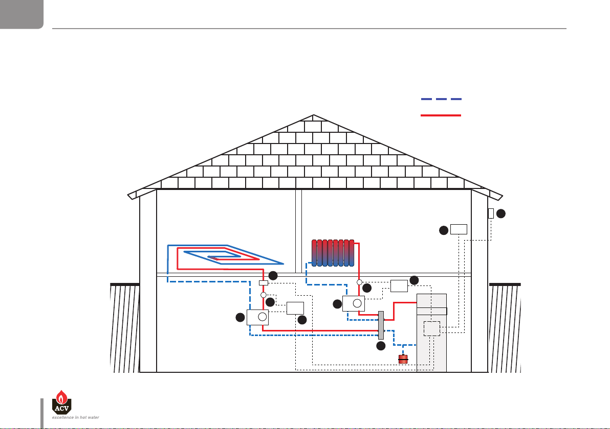
HIGHTEMPERATURE HEATING CIRCUIT CONTROLLED BY A ROOM THERMOSTAT

en
7
ENConneCtion Diagrams anD aCCessories
660Y1400 - A
Required optional material
Applicable to Description Code
All HM TC models Room thermostat ACV 22 10800018
HM 25 / 35 / 45 TC High temperature kit DN 25 : comprised of a heating pump, two isolating valves, a check valve,
two thermometers. 10800294
HM 70 / 85/ 120 TC High temperature kit DN 32 : comprised of a heating pump, two isolating valves, a check valve,
two thermometers. 10800296
1
2
2

Remove this link to
connect the room
thermostat.
1 2 3 4 5 6 7 8 9 10 11 12 13
1 2 3 4 5 6
EN
en
8
ConneCtion Diagrams anD aCCessories
660Y1400 - A
Block diagram for wiring in accordance with applicable standards.

en
9
ENConneCtion Diagrams anD aCCessories
660Y1400 - A
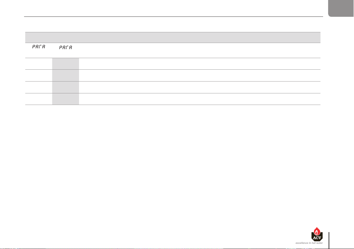
Setting the MCBA
Initial Adjusted DESCRIPTION
3. 0 1 3. 0 1 00 : Heating mode “OFF”
01 : Heating mode “ON”
4. 85 4. 85 Preset temperature for the heating circuit water (adjustable between 30 and 85°C.
p. 4 5
. 00
p. 4 5
. 00 00 : Using an outdoor sensor and a room thermostat
Cold water
Hot water
EN
en
10
ConneCtion Diagrams anD aCCessories
660Y1400 - A
INSTALLATION OF TWO HEATING CIRCUITS CONTROLLED BY ROOM UNIT AND ZMC2 MODULE
MCBA
M
M
3
3
1
5
7
7
4
2
2
6

en
11
ENConneCtion Diagrams anD aCCessories
660Y1400 - A
Required optional material
Applicable to Description Code
All HM TC models Room Unit RSC
Delivered with outdoor sensor 10800034
All HM TC models
ZMC-2 Module (kit)
Manages the second heating circuit - alarm contact - only functions in conjunction with
the Room Unit RSC.
10800218
X2
All HM TC models Clip-in interface RMCIEBV3
Enables communication between the MCBA and the Room Unit RSC.10800036
All HM TC models 2k — VF202 contact sensor
For outlet on controlled circuit
10800045
X2
All HM TC models RAM 5109 contact thermostat
Mandatory to protect all the oor heating circuits. 10510900
All HM TC models 12k — AF120 outdoor sensor 10510100
HM 25 / 35 / 45 TC 2 circuit manifold DN 25
With connection pipes and built-in wall mounts
10800208
HM 25 / 35 / 45 TC
Low temperature kit DN 25
Is comprised of a heating pump, two isolating valves, a check valve, two thermometers and a 3-way valve
with built-in bypass.
10800295
HM 70 / 85/ 120 TC 2 circuit manifold DN 32
With built-in wall mounts. 10800298
HM 70 / 85/ 120 TC Manifold connection kit DN 32
Includes two stainless steel hoses Ø 1"1/2 with Ø 1"1/4 reducer 10800142
HM 70 / 85/ 120 TC
Low temperature kit DN 32
Is comprised of a heating pump, two isolating valves, a check valve, two thermometers and a 3-way valve
with built-in bypass.
10800297
X2
HM 70 / 85/ 120 TC Servomotor ARA661
Motor for 3-way valve DN 32 with the low-temperature kit.
10800199
X2
3
2
1
4
5
6
7
6
7
6
7

ZMC-2
(230 Volt)
A B VF 0VE 0
VF202
12345678910111213
2
1
BUS A
BUS B
BUS A
BUS B
BUS B
BUS A
BUS B
BUS A
ZMC-2
(230 Volt)
A B VF 0VE 0
VF202
L
1L 2 3 N
NPE
VA
N N N
M
230 Volt - 6A
50Hz
L
1L 2 3 N
NPE
VA
N N N
M
230 Volt - 6A
50Hz
Block diagram for wiring in accordance with
applicable standards.
10800036: Interface address “0”
= 7
= 6
= 5
= 4
= 3
= 2
= 1
= 0
EN
en
12
ConneCtion Diagrams anD aCCessories
660Y1400 - A
en
13
ENConneCtion Diagrams anD aCCessories
660Y1400 - A
Setting the MCBA
Initial Adjusted DESCRIPTION
1. 60 1. 60 Maximum temperature of preset Domestic Hot Water temperature
2. 0 1 2. 0 1 00 : DHW mode “OFF”
01 : DHW mode “ON”
3. 0 1 3. 0 1 00 : Heating mode “OFF”
01 : Heating mode “ON”
4. 85 4. 85 Maximum temperature of the heating circuit (must be higher than the DHW temperature.
CASCADE INSTALLATION
For information on the installation of several HeatMaster® TC boilers in a cascade, please contact your ACV representative.

EN
en
14 660Y1400 - A
MCBA PARAMETERS FOR THE SPECIALIST
STANDBY MODE
When the boiler is switched on, it starts up in Stand-by mode, as shown in the figure above.
This is the standard mode of the MCBA. The MCBA automatically returns to this mode after 20 minutes if no key is pressed on the MCBA interface. The
new parameters will become active.
The first digit indicates the boiler’s current status, depending on the situation of the boiler and the burner. The last two digits indicate the boiler
temperature.
Status Boiler Function
0Standby, no heat demand
1Fan pre-purge/post-purge
2Ignition
3Operation of the burner for heating
4Operation of the burner for domestic hot water production
5Waiting for a signal from the air pressure switch or to obtain number of start revolutions.
6The burner is off because the set value has been reached. There is still a demand for heat..
7Heating pump time delay after demand for heating.
8Heating pump time delay after demand for DHW.
9Blocked burner: refer to "Blockage and Error Codes", page 30

en
15
ENMCBA PArAMeters for the sPeCiAlist
660Y1400 - A
If the burner is blocked for one of the above reasons, the display toggles between "9" and the temperature (last two digits) and “b” with the error
code
Once the cause of the blocking has been resolved, the burner starts up automatically after a maximum of 150 seconds..
Status Boiler Function
Internal adjustment — Three-way valve
Boiler burner on - temperature is maintained
Test function: max RPM in CH mode.
Test function: min RPM in CH mode.
Test function: burner on with fixed fan speed

EN
en
16
MCBA PArAMeters for the sPeCiAlist
660Y1400 - A
PARAMETER MODE
SETTING THE MCBA PARAMETERS
To access the Parameter mode when the system is in Standby mode, press the “MODE” key once.
To scroll through the list of parameters press the “STEP” key. To modify the value of the parameter, use the “+” or “-” keys.
Then, press the “STORE” key to save the modified value. The screen will flash once to confirm the data has been
saved.
To activate the modified parameters, press “MODE” again (this will switch you to Info mode). However, if you do not
press any key, the system returns to Standby mode after 20 minutes and activates the changes.
Factory settings
STEP Display Parameter Description HM 25 / 35 / 45 / 70 / 85 /120 TC HM 71 / 101 / 201
1. 67 Setting the hot water temperature 1. 60 1. 90
2. 0 1
Hot water production DHW
00 = OFF
01 = ON
2. 0 1 2. 0 1
3. 0 1
Switching heating On/Off
00 = OFF
01 = ON
3. 0 1 3. 0 1
4. 70 Maximum temperature in central heating mode
CH4. 85 4. 90
DISPLAY
MODE

en
17
ENMCBA PArAMeters for the sPeCiAlist
660Y1400 - A
INFO MODE
INFORMATION ON THE INSTALLATION
To switch from Stand-by mode to Info mode, press the “MODE” key twice
Press the “STEP” key until the desired information is displayed.
The dot located behind the first position flashes to indicate that the boiler is in Info mode.
DISPLAY
MODE
MODE
STEP Display Parameter Description
1. 60 Flow temperature T1 in °C
2. 50 Return temperature T2 in °C
3. 65 DHW temperature T3 in °C
4. 03 Outside temperature T4 in °C
5. 55 Flue gas temperature T5 in °C
6. 45 Flow temperature set-point calculated in °C
7. 00 Rate of increase of flow temperature in °C/S

EN
en
18
MCBA PArAMeters for the sPeCiAlist
660Y1400 - A
STEP Display Parameter Description
8. 00 Rate of increase of return temperature in °C/S
9. 00 Rate of increase of DHW temperature in °C/S
a. 34 Flow temperature of 2nd central heating circuit
N/A
c. 00 N/A
N/A
E. 00 Ionisation current
F. 0 0 N/A
N/A
h. 42 Internal MCBA temperature
i. 00 Number of CH starts X 10000

en
19
ENMCBA PArAMeters for the sPeCiAlist
660Y1400 - A
STEP Display Parameter Description
Number of CH starts X 100
Number ofCH starts X 1
Number of hours of CH operation X 10000
Number of hours of CH operation X 100
Number of hours of CH operation X 1
Number of DHW starts X 10000
Number of DHW starts X 100
Number of DHW starts X 1
Number of hours of DHW operation X 10000
Number of hours of DHW operation X 100
Number of hours of DHW operation X 1

EN
en
20
MCBA PArAMeters for the sPeCiAlist
660Y1400 - A
CODE MODE
ENTERING THE CODE
By entering the code you can access from
Parameter 10 to Parameter 113 and consult the
communication mode, the fan speed mode and
the Error mode.
Only ACV approved installers know the
access code.
For more information, please contact
our after-sales service.
To access the Code mode, press simultaneously on MODE and STEP.
(Only inStand-by mode!]
Press once on theSTEP key and the screen displays “C”
in the first position then random characters in the third and fourth positions.
Press on "+" or "-" key to change the code
Press the STORE key, the screen flashes
briefly to indicate that the code has been accepted.
Press the MODE key until the desired
mode appears.
MODE STEP
STEP
+ -
or
STORE
This manual suits for next models
8
Table of contents
Popular Control System manuals by other brands


auto maskin
auto maskin DCU 305 R2 Communications manual

heat-timer
heat-timer SQ-Elite-8T Installation and operation instruction manual
De Haardt
De Haardt XTRA.BEACON user manual

YOKOGAWA
YOKOGAWA Centum VP technical information

urmet domus
urmet domus 1033 Installation and instruction manual

Fagor
Fagor CNC 8055 T Examples Manual


