FUTABA R7018SB User manual

R7018SB
●Applicablesystems:FutabaFASSTest-2.4GHz/FASST-Multi-chsystemtransmitter
The R7018SB has a Dual Battery System. Multiple servos can be driven by connecting 2 large capacity batteries. Even if the voltage
RIRQHEDWWHU\GURSVWKHRWKHUEDWWHU\DOORZVVDIHÀLJKW7KHR7018SB can also be switched the FASST-Multi-ch System.
◆FASSTest-2.4GHz Bidirectional Communication System / FASST-Multi-ch 2.4GHz
◆Dual Battery ◆S.BUS2 / S.BUS Port and 18 Channels for Conventional System Receiver
1M23N30102
CONTENTS
ESC(motorcontroller)thatsuppliespower
fromthedrivebattery(BEC-BatteryEliminator
Circuit)tothereceivercannotbeused.
Ordinaryswitches
(SSW-J,HSW-J,HSW-L,
etc.)cannotbeused.
Usageprecaution
• Analog servos cannot be used with the R7018SB in the
FASSTest 12CH mode.
• When the FASST Multi-ch High-speed Mode is used, analog
servos cannot be used at the CH1 〜6 outputs for convention
systems. However, in other than the FASSTest 12CH mode,
analog servos can be used at CH7 〜16, DG1 and DG2 at
any time.
• Don't connect to Extra Voltage Telemetry Port before turning
on a receiver.
WARNING
Changesormodificationnotespeciallyapprovedbytheparty
responsibleforcompliancecouldvoidtheuserʼ sauthorityto
operatetheequipment.
Whenthemodelisnotbeingused,alwaysremoveor
disconnectthebattery.
■When the switch is off, a slight amount of current still flows. Unless the
switch and battery are disconnected, the battery will be damaged from
excessive discharge.
TheR7018SBreceivershouldbeprotectedfromvibrationby
foamrubber,Velcro,orsimilarmountingmethods.Protectfrom
moisture.
Keepawayfromconductivematerialstoavoidshortcircuits.
Whenonlyonebatteryisconnected,alwaysinsulatethe
unusedconnector.
Antennainstallationprecaution
Donotcutorbundlethereceiverantennawire.
Donotbendthecoaxialcable.Itcausesdamage.
Theantennasmustbemountedinsuchawaytoassurethey
arestrainrelieved.
Keeptheantennaasfarawayfromthemotor,ESCandother
noisesourcesasyoupossiblycan.
Besurethatthetwoantennasareplacedat90degreestoeach
other.
■The R7018SB has two antennas. In order to maximize signal
reception and promote safe modeling Futaba has adopted a diversity
antenna system. This allows the receiver to obtain RF signals on both
antennas and fly problem-free.
Antennainstallationforcarbonfuselage
Youmustleave30mmatthetipoftheantennafullyexposed.
Theexposedantennashouldbesecuredsothatitcannotmove
aroundorbackinsideofyouraircraft.
Becarefulofconnectorinsertion
Don'tconnectanS.BUSservo/gyrotoS.BUS2connector.
Donotconnectthepowersupplybatterytootherthanthe
powersupplyconnector.
■There is the danger of ignition, explosion, or burning.
Linkprecaution
Donotperformthelinkingprocedurewhilethemotor'smain
powerconnectedortheengineisoperatingasitmayresultin
seriousinjury.
Whenthelinkingiscomplete,pleasecyclethereceiverpower
andensurethereceiverisproperlylinkedtothetransmitter.
Pleasepowerupyoursysteminthisorder.Transmitterfirst,
followedbythereceiver.
IftheR7018SBreceiverwaspreviouslylinkedtoanother
transmitter,makesurethattransmitterisnotoperatingwhile
linkingthereceivertothenewtransmitter.
56% ¼
([FOXVLYHVZLWFK ¼ 0LQLGULYHU ¼
)HPDOH'HDQV
8OWUD3OXJ ¼
+HDWVKULQNWXEH
/LQN0RGH
VZLWFK
%DWWHU\FRQQHFWRU
'HDQV8OWUD3OXJ
$QWHQQD
0RGH/('
/LQN/('
%DWWHU\%/('
%DWWHU\$/('
UseaDeansUltraPlugwith
theR7018SBpowersupply
battery.Batteriesofthis
connectorcannotbeused.
([WUD9ROWDJH
7HOHPHWU\3RUW
Thank you for purchasing a Futaba R7018SB FASSTest-2.4GHz compatible receiver.The R7018SB receiver features bi-directional
communication with a FASSTest Futaba transmitter using the S.BUS2 port. Using the S.BUS2 port an impressive array of telemetry
sensors may be utilized. It also includes both standard PWM output ports and S.BUS output ports.
ComplianceInformationStatement
(forU.S.A.)
This device, trade name Futaba Corporation, model number R7018SB,
complies with part15 of the FCC Rules. Operation is subject to the following
two conditions:
(1) This device may not cause harmful interference, and
(2) This device must accept any interference received, including interference
that may cause undesired operation.
(3) This module meets the requirements for a mobile device that may be used
at separation distances of more than 20cm from human body.
To meet the RF exposure requirements of the FCC this device shall not be co-
located with another transmitting device.
The responsible party of this device compliance is:
Futaba Service Center
3002 N Apollo Drive Suite 1, Champaign, IL 61822 U.S.A.
-1-

90˚
(Antenna installation)
Connector
The direction of the connectors of the bottom 3 ports is
GLIIHUHQWE\Û
56%
&+6HUYRV
6%86VHUYRV
6%86*\URV
5HFHLYHUق6HUYRك%DWWHU\$
HJ/LSRFHOO岜9
5HFHLYHUق6HUYRك%DWWHU\%
HJ/LSRFHOO岜9
+XE
+XE
([FOXVLYHVZLWFK
6%86HTXLSPHQW
7HOHPHWU\VHQVRU
7HOHPHWU\VHQVRU
6%86
3RUW
6%86
3RUW
D
G
D
G
'RQRWFRQQHFW
DEDWWHU\WR
WKHSRUWVDW
WKLVVLGH
%DWWHU\
FRQQHFWRU
Donotuseabatteryofthe
wrongratedvoltageand
type(Li-po,Li-Fe,etc.).
Whenthereceiverisnotin
use,alwaysdisconnectthe
battery.
WARNING
Neverreversethebatterypolarity.
■A reverse connection the battery terminals may cause
abnormal heating, fire and burns.
Donotshortcircuitthebatteryterminals.
■A short circuit across the battery terminals may cause
abnormal heating, fire and burns.
Becarefulwhensolderingtotheplug;don'toverheat
theplugwithyoursolderingironandtakegreatcareto
avoidshort-circuitsontheplug.
■Such a overheat and short-circuit would destroy the plug.
LEDIndication
System ModeLED Status LinkLED
FASSTest GreenSolid
Nosignalreception RedSolid
Receivingsignals GreenSolid
Waitingforlink Start → 2secondlater → Red
Blink(1second)
FASST Off
Nosignalreception RedSolid
Receivingsignals GreenSolid
ReceivingsignalsbutIDisunmatched GreenBlink
Waitingforlink RedBlink
FASSTest
FASST −Unrecoverableerror(EEPROM,etc.) Alternateblink
*Fixed at neutral if a servo is connected to a port other than a usable
transmitter channel.
*The telemetry and Extra Voltage ports cannot be used with the
FASST system.
FASSTest ⇔ FASST(Normal-High-speed)
Changemethod
1. Turn on the receiver.(Transmitter OFF)
2.Press and hold the Link/Mode button for more then 5 second.
3. When the LED begins to blink green/red the button may be
released.
4. The LED should now be blinking red in one of the patterns
described by the chart below.
( Default : FASSTest )
5.Each press of the Mode/Link button advances the receiver to
the next mode.
6.When you reach the mode that you wish to operate in, press
and hold the Mode/Link button for more than 2 seconds.
7. Once locked into the correct mode the LED will change to a
solid color.
8.Please cycle the receiver(s) power off and back on again
after changing the Channel Mode.
RedLEDblink System
1time FASSTest
2time FASSTMulti-ch
Normalmode
3time FASSTMulti-ch
High-speedmode
Connection
FemaleDeansUltraPlug
Soldering
BatteryWire
Heatshrink
tube
-2-

DualBatterySystem
Two power supply batteries can be connected to the R7018SB. Power is supplied from
the battery with the highest voltage. The operating time is the total time of the 2 batteries.
For example, even if the voltage of one battery drops, power can be supplied from the
RWKHUEDWWHU\(YHQRQHEDWWHU\FDQEHXVHGEXWVDIHUÀLJKWLVSRVVLEOHLIEDWWHULHVDUH
used.
This receiver employs an electronic switching (current is controlled by an FET circuit) system. When the exclusive switch is
set to ON or is pulled, the power is turned on. Switches other than the exclusive switch cannot be used. In addition, since a
YHU\VPDOOFXUUHQWÀRZVHYHQZKHQWKHSRZHULVRIIDOZD\VGLVFRQQHFWWKHEDWWHU\IURPWKHFRQQHFWRUZKHQWKHUHFHLYHULVQRW
in use.
One or 2 batteries can be connected. When 2 batteries are connected, the battery with the highest voltage is used. When only
one battery is connected, always insulate the unused connector. The battery can be connected to either side.
In addition, since this receiver does not have a built-in voltage regulator, use batteries with sufficient capacity for the
VSHFL¿FDWLRQVDQGQXPEHURIVHUYRPRWRUVWREHXVHG
56%
([FOXVLYHVZLWFK
5HFHLYHUق6HUYRك%DWWHU\$
HJ/LSRFHOO岜9
5HFHLYHUق6HUYRك%DWWHU\%
HJ/LSRFHOO岜9
D
G
D
G
Evenifthevoltageof
oneofthebatteries
drops,powerissupplied
fromtheotherbattery.
Evenifthepowersupply
wiringofoneofthebatteries
breaks,powerissupplied
fromtheotherbattery.
WhentheswitchissettoON,
powerissuppliedfromthebattery
withthehighestvoltage.The
operatingtimeisthetotaltimeof
the2batteries.
Electricpowerwillbeautomatically
andalternativelysuppliedfromthe
batterywhichvoltageishigher.
LEDofthebatterybeing
usedlights.
FASSTest
FASSTest
FASSTest is a bidirectional communication system between the R7018SB receiver and FASSTest capable transmitters.
Multiple optional telemetry sensors may be connected to the S.BUS2 on the receiver and that data is in turn displayed on
the transmitter.
*Please see your transmitters operation manual to configure transmitter to operate with telemetry sensors.
Linktothetransmitter:FASSTest
1Bring the transmitter and the receiver close to each
other, within 20 inches (half meter).
2Turn on the transmitter. Place the transmitter into the
receiver linking mode.
3Turn on the receiver.
4The receiver will wait for the linking process to begin
for 2 seconds. Following that it will return to the normal
operation mode.
5When the LED of the receiver changes from blinking red
to solid green, linking is complete.
(A link waiting state is ended in 1 second.)
•Refer to the transmitters operation manual for complete
details on how to place the transmitter into the linking
mode.
• If there are many FASSTest systems turned on in close
proximity, your receiver might have difficulty establishing
a link to your transmitter. This is a rare occurrence.
However, should another FASSTest transmitter/receiver
be linking at the same time, your receiver could link to
the wrong transmitter. This is very dangerous if you do
not notice this situation. In order to avoid the problem,we
strongly recommend you to double check whether your
receiver is really under control by your transmitter.
• If the System Type of the transmitter is changed, the
receiver will need to be re-linked to the transmitter.
S.BUS2
S.BUS2 extends S.BUS and supports bidirectional
communication. Sensors are connected to the S.BUS2
port.
*Only S.Bus2 capable devices may be connected to the S.Bus2
port. Standard S.Bus servos and gyros should not be connected
to the S.Bus2 port.
Receivervoltagetransmitterdisplay
The voltage displayed at the transmitter is only that of the
battery currently in use (battery with the highest voltage).
*The voltage of the 2 batteries cannot be displayed individually.
ExtraVoltageTelemetryport
It connects with the battery for power, etc.
External voltage input cable (CA-RVIN-700) of an option
is used. The voltage of the battery can be displayed with a
transmitter.
+
−
-3-
BatteryA BatteryB
Suppliedfrom
batteryA
Suppliedfrom
batteryB
Suppliedfrom
batteryB

Linktothetransmitter:FASST
1Bring the transmitter and the receiver close to each
other, within 20 inches (half meter).
2Turn on the transmitter and receiver.
3Link operation is performed by the Link/Mode switch.
• When using TM-8 module, it's possible to set F/S position (only 3CH).
0 to 1 sec. 1 to 2 sec. More than 2 sec.
0 sec. 1 sec. 2 sec.
Press and Hold time
No function
With TM-8
(not included in this set)
To set the F/S
position(No re-link)
Re-link(ID set) and to
set the F/S position
No function
Besides TM-8 Re-link(ID set)
*Refer to the instruction manual of the transmitter or module used
for a description of the linking operation, F/S position setting
methods and other details.
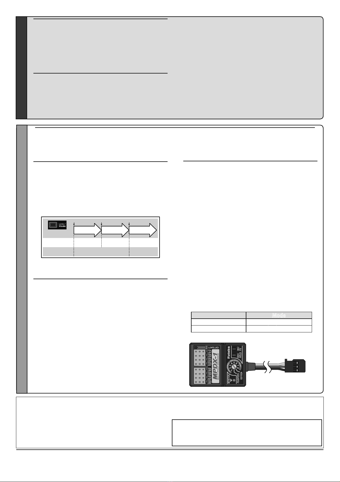
WhenusingMultiprop(MPDX-1)
The MPDX-1 can be used with FASSTest by merely
setting the corresponding transmitter. (Refer to the
instruction manual of the corresponding transmitter.)
When using the MPDX-1 Multi Prop Decoder (sold
separately) with the FASST system, change the setting by
the following method.
Enable the MPDX-1 at channels 11 and 12. (Initial value:
OFF)
Channels 11 and 12 cannot be used individually for
MPDX-1 output.
The MPDX-1 extends 1 channel to 8 channels. However,
since the response speed becomes slower and there are
functional restrictions, use it at simple switch operation
and other applications that require numerous channels.
MultipropmodeChangemethod
1. Switch the receiver to the FASST system (Normal or
High-speed).
2. Turn on the receiver power. (Transmitter power off)
3. Press the Link/Mode switch for at least 10 seconds.
4. When the LED blinks red and changes to red/green
simultaneous rapid blinking, release the switch.
5. The receiver enters the multi prop mode and the LED of
the current mode blinks. (Initial value: OFF)
6. Each time the switch is pressed, the mode changes.
7. When the receiver was switched to the desired mode,
press the Link/Mode switch for at least 2 seconds.
8. When the LED switches to red/green simultaneous
rapid blinking, mode switching is complete. Release the
switch.
9. When switching is complete, turn on the power. When
the power is turned on, the receiver switches to the new
mode.
FASST
When switched, the R7018SB can use the FASST-Multi-ch mode. When the FASST system is used, the telemetry and
Extra Voltage ports cannot be used. The FASST system has a Normal mode and a High-speed mode. However, in the
High-speed mode, analog servos cannot be used at CH1 〜6.
GreenLEDblink Mode
1time MultipropmodeOFF
2time MultipropmodeON
FASSTest FASST
Whenatelemetryadapter(TMA-1)isused
:FASSTestonly
When using a TMA-1 (sold separately), change the
settings by the following method.
The TMA-1 is a device for viewing the telemetry data on
a smartphone or tablet.
R7018SBandTMA-1linkingmethod
1. Switch the receiver to FASSTest system.
2. Link the transmitter and receiver, and after confirming
operation, turn off the power.
3. Turn on the receiver power. (Transmitter power off)
4. Press the Link/Mode switch for at least 10 seconds.
5. After the LED blinks red and changes to red/green
simultaneous rapid blinking, release the switch.
6. The receiver enters the linked with TMA-1 mode, and
the LED begins red/green simultaneous rapid blinking.
7. Press the TMA-1 link switch until the LED starts to blink
and wait for the TMA-1 to link.
8. When TMA-1 linking is complete, the TMA-1 LED
changes from red to green for a moment.
9. When linking is complete, turn on the receiver power
and check the operation of all the devices.
03';ق2SWLRQك
FUTABA CORPORATION
1080 Yabutsuka, Chosei-mura, Chosei-gun, Chiba-ken, 299-4395, Japan
Phone: +81 475 32 6982, Facsimile: +81 475 32 6983
©FUTABA CORPORATION 2015, 4 (1)
R7018SBSpecifications
FASSTest-2.4GHz system(18CH/12CH mode)FASST-2.4GHz system
(Multi-ch mode)
S.BUS2 and S.BUS port and Linear 16 ch +Digital 2 ch for conventional
system receiver
• Dual antenna diversity
• Size: 2.15 x 1.59 x 0.64 in. (54.6x40.4x16.3mm)
• Weight: 1.48 oz. (42g)
• Power requirement: 6.0V to 7.4V(Voltage range: 4.8 to 8.4V)
• Battery F/S Voltage: It sets up with a transmitter (F/S can't be used in
case of FASST.)
• Extra Voltage port: 0 〜70V DC
- 4-
All product and company names mentioned
herein are the trademarks or registered
trademarks of their respective owners.
本產品符合低功率電波輻射性電機管理辦法 第十二條、第十四條等條文規定
1. 經型式認證合格之低功率射頻電機,非經許可,公司、商號或使用者均不得擅自變更頻率、加
大功率或變更原設計之特性及功能。
2. 低功率射頻電機之使用不得影響飛航安全及干擾合法通信;經發現有干擾現象時,應立即停用,
並改善至無干擾時方得繼續使用。前項合法通信,指依電信法規定作業之無線電通信。低功率
射頻電機須忍受合法通信或工業、科學及醫療用電波輻射性電機設備之干擾。

©FUTABACORPORATION 2015,8(1)
RegardingtheNumberofServoConnections
TheR7018SBreceiverhasahighlyreliable,dualbatterypowercircuit.
Regularlyrunningalargecurrentthroughthepowercircuitwillcausethe
internaltemperaturetoincrease,leadingtodamageoftheinternalcircuitry;
thus,youshouldavoidunnecessarylinkagesandsimultaneoususageof
multiplehigh-torqueservos.
■Ratedcurrent:12A(peak20A)
Asarule,youshouldnotusemorethansixFutabahigh-torque(*)servoswith
thisreceiver.
Also,donotinstallthereceivernearheatsourcessuchasenginesormufflers.
*High-torque servos = Servos for large machines (i.e., having torque equal to or
exceeding the BLS172SV or BLS177SV)
For other functions and features, please refer to the enclosed manual.
To get the longest life out of your receiver, read and follow the instructions in the manual.
1M23N30104
56%
D
G
D
G
CAUTION
Nomorethan6high-torqueservos
(e.g.,BLS172SV,BLS177SV)
Table of contents
Other FUTABA Receiver manuals

FUTABA
FUTABA R6203SB User manual

FUTABA
FUTABA R303FHS User manual

FUTABA
FUTABA R314SB User manual

FUTABA
FUTABA 4PM How to use

FUTABA
FUTABA R3006SB User manual

FUTABA
FUTABA R7308SB User manual

FUTABA
FUTABA FASSTest R7103SB User manual

FUTABA
FUTABA R6014FS User manual

FUTABA
FUTABA R7008SB User manual

FUTABA
FUTABA R304SB User manual

FUTABA
FUTABA R7208SB User manual

FUTABA
FUTABA R6208SB User manual

FUTABA
FUTABA R314SB-E User manual

FUTABA
FUTABA R6004FF User manual

FUTABA
FUTABA R3206SBM User manual

FUTABA
FUTABA R3106GF User manual

FUTABA
FUTABA R6008HS User manual

FUTABA
FUTABA T10PX User manual

FUTABA
FUTABA S.Bus 2 User manual

FUTABA
FUTABA R204GF-E User manual