manuals.online logo
Brands
  1. Home
  2. •
  3. Brands
  4. •
  5. FUTABA
  6. •
  7. Receiver
  8. •
  9. FUTABA R608FS User manual

FUTABA R608FS User manual

How to Get the Best Performance from Your Futaba
®
2.4GHz
FASST™ Aircraft Recei ers
Every R/C pilot learns by experience what methods work well for installing and
maintaining radio equipment. t the same time, we also want our aircraft to have the
advantage of up-to-the-minute technology...which means that every now and then, we
must master some new techniques.
Spread spectrum radio technology offers the perfect example. When Futaba
introduced 2.4GHz F SST radio equipment, R/C hobbyists quickly jumped to the front
of electronic technology’s cutting edge. Not surprisingly, those new, state-of-the-art
2.4GHz receivers have significant differences compared to old 72MHz units. So it’s time
to change a few old habits.
Below are some recommendations for updating the way you install and maintain radio
gear. Make them a part of your routine, and you’ll enjoy the best performance from your
2.4GHz F SST radio gear.
1. Don’t wrap your FASST recei er in foam.
Protecting your receiver from vibration by wrapping it in foam used to be a “must”.
Not so with 2.4GHz F SST receivers. Unlike 72MHz equipment, they’re not as
vulnerable to vibration. Using less foam lets them operate cooler — which is a plus for
all electronics.
Tip: To keep the receiver cooler use small foam blocks (like standoffs) so that there is
an air channel around the receiver.
2. Shade your model from sunlight when not flying.
Clear canopies expose the radio compartment to direct sunlight which results in
additional heat in the model interior. This causes no problems during flight, but makes
shading your model on the ground very important. Cover the canopy with a white towel;
or better yet, park your airplanes in the shade. This will help keep the electronic
components cool.
Tip: It is important to note that lighter covering colors will absorb less heat whereas
darker colors will absorb more heat.
3. Mount your FASST recei er away from heat sources.
We had to avoid mounting 72MHz receivers near anything that might produce RF
noise. That’s not as much of a concern with 2.4GHz F SST receivers — you should
instead make sure that you’re mounting the unit in the coolest part of the radio
compartment.
Stay away from the muffler exhaust, battery packs, regulators or any other heat
source. We also recommend that you use the receiver’s long, narrow side as its base
(rather than mounting it with the bottom flat against the radio compartment floor). Secure
the receiver using a Velcro® strap or gel tape.
We hope that these tips help you with your 2.4GHz F SST receiver installation and
maintenance. If you have any questions, please let us know. Just contact us at the Futaba
Service Center, by e-mail at: [email protected]m.
Important: The 2.4
G
Hz band offers different characteristics tha
n
t
hat o
f
the conventional 50MHz and 72MHz. As such, we strongl
y
e
ncourage you to read this manual care
f
ully prior to utilizing the TM-
8
a
nd R608F
S
FA
SS
T s
y
stem
.
1M2
3
N2
0
1
01
&
R
Q
W
H
Q
W
V
D
Q
G
7H
7H
F
K
Q
L
F
D
O
6
S
H
F
L
À
F
DW
W
L
R
Q
V
Your 2.4GHz system includes the following components
:
6S
HFL
À
FDWLRQV
TM-8 RF Module
-
•
Communication
s
ystem
:
o
ne-wa
y
commun
i
cat
i
o
n
•
A
ntenna: 1/2 wave
l
engt
h
di
-
p
o
le
•
Curren
t
consum
p
t
i
on
:
1
50m
A
max
i
mu
m
•
Settin
g
s
w
i
tc
h
fo
r
F
a
il
S
af
e
(
F/S) sett
i
ng
a
n
d
range
ch
ec
k
• LED
(light
e
m
i
tt
i
n
g
d
iodes)
i
n
di
cate t
he
o
p
erat
i
ona
l
s
tatus
R
608FS Receiver-
•
Dual
a
nt
e
nn
a
di
vers
i
t
y
•
P
owe
r
r
e
q
u
i
rement
:
4.8V or 6.0V
b
atter
y
o
r
r
egu
l
ate
d
ou
t
-
p
u
t
from ESC
,
e
tc
.
(
*1
)
•
F/S an
d
B
atter
y
F
/S function fo
r
t
h
rott
le
c
h
anne
l
(channel
three)
• Size
:
0
.98
x
1
.86
x
0
.56
in.
(24.9
x
47.
3
x
1
4.3 mm)
•
W
e
i
g
h
t
:
0.4
8
o
z.
(
13.5g)
(*
1
)
Be
sure
th
at
wh
e
n usin
g
ESC
'
s
r
e
g
ulate
d
o
utpu
t
th
e
capacit
y
of
t
h
e
E
SC
m
us
tm
ee
t
yo
u
r
usage
co
n
d
iti
o
n
.
T
M-
8
RF Module
FASST Air Syste
m
TM-
8
RF Mo
d
u
l
e
a
n
d
R608FS Receiver
T
h
an
k
you for purc
h
as
i
ng t
h
e TM-8 2.4GHz FASST transm
i
tter mo
d
u
l
e
and R608FS receiver. This s
y
stem is desi
g
ned for use onl
y
with the
F
u
ta
b
a tran
s
mitt
e
r
s
in
d
i
c
at
ed
e
l
sew
h
e
r
e
in thi
s
man
u
al
.
In
o
r
de
r t
o
use
th
e
TM-8 transmitter module,
y
ou will need to carefull
y
remove the existin
g
transmitter module and re
p
lace it with the TM-8 transmitter module. The
receiver R608FS, as the model number indicates, is capable of controllin
g
mo
d
e
l
s up to e
igh
t c
h
anne
l
s. P
l
ease note: T
h
e
i
nsta
ll
at
i
on of t
h
e R608FS
di
ffers s
li
g
h
t
l
y from t
h
at of a typ
i
ca
l
rece
i
ver. P
l
ease pay spec
i
a
l
attent
i
on
n
format
i
on conta
i
ne
d
w
i
t
hi
n t
hi
s manua
l
i
n or
d
er to
h
ave a p
l
easant
H
[SHU
L
HQFH
res:
re
re
s
:
$
SSOLFDEOHV
\
VWHPV
T7U, T8U, T9C and T9Z
R
608FS Receiver
M
ini
sc
r
e
w
d
riv
er
Instruction Manual
R
epair Service (in U.S.A.)
,
IDQ\ GLI¿FXOWLHV DUHHQFRXQWHUHG ZKLOHVHWWLQJ XS RURSHUDWLQJ
your TM-8 transmitter module and R608FS receiver, please
consu
l
t t
hi
s
i
nstruct
i
on manua
l
f
i
rst. For furt
h
er ass
i
stance
y
ou ma
y
a
l
so refer to
y
our
h
o
bby
d
ea
l
er, or contact t
h
e Futa
b
a
Serv
i
ce Center at t
h
e we
b
s
i
te, fax or te
l
ep
h
one num
b
er
b
e
l
ow
:
w
ww.futaba-rc.com, www.2.4gigahertz.co
m
F
ax
(
217
)
398-7721, Tel
(
217
)
398-8970
(
o
p
tion 2
)
I
f you are unable to resolve the issue, pack the system in its
original container with a note enclosed and a thorough, accurate
G
HVFULSWLRQRIWKHGLI¿FXOW\,QFOXGHWKHIROORZLQJLQ\RXUQRWH

S
ymptoms (Includin
g
when the problem occurred)
Sy
stem (transmitter, Receiver,
S
ervos and model
n
umbers
)
M
odel
(
Model name
)
M
odel numbers and quantity
Y
our Name, Address and Tele
p
hone number
Send the res
p
ective items to the authorized Futaba Service
C
enter address below:
F
utaba
S
ervice
C
enter
3
002 N Apollo Drive Suite 1
Champai
g
n, IL 6182
2
•
•
•
•
•
Special Markings;
Pay special attention to the safety at
the parts of this manual that are
indicated by the following marks.
[Symbol] ; Prohibited ; Mandatory
Mark Meaning
Procedures which may lead to a dangerous condition and cause
death or serious injury to the user if not carried out properly.
Procedures which may lead to a dangerous condition or cause death
or serious injury to the user if not carried out properly, or procedures
where the probability of superficial injury or physical damage is high.
Procedures where the possibility of serious injury to the user is
small, but there is a danger of injury, or physical damage, if not
carried out properly.
B
atter
y
F
/S
f
unction
The TM-8 transmitter module and R608F
S
receiver also
provides
y
ou with a second safet
y
s
y
stem, the Batter
y
F/S
(failsafe). When the airborne volta
g
e drops below 3.8V, the
b
attery fa
il
safe funct
i
on moves t
h
e t
h
rott
l
e to a pre-
d
eterm
i
ne
d
pos
i
t
i
on. If t
hi
s
h
appens, you s
h
ou
ld
l
an
d
i
mme
di
ate
l
y! I
f
you nee
d
to
i
ncrease t
h
e t
h
rott
l
e for your
l
an
di
ng approac
h
,
you may temporar
il
y reset t
h
e fa
il
safe funct
i
on
b
y mov
i
ng t
h
e
throttle stick to the predetermined position, after which
y
ou'll
have about 30 seconds of throttle control before the batter
y
f
u
n
c
ti
o
n r
e
a
c
ti
v
at
es.
*
Pleas
e
n
o
t
e: I
t
is
s
u
gg
este
d
tha
t
yo
u utilize
a
4-cel
l
N
i
C
D
or
NiMH
receive
r
b
atter
y
pac
k
as
it
a
llows
t
he e
ff
ectiv
e
u
se
o
f
t
he
b
atter
y
F/S
f
unction.
A
dditionall
y
,w
e
do
no
t
su
gg
es
t
u
sin
g
d
r
y
cel
l
batterie
s
f
o
r
W
KHUHFHLYHUSDFNDVWKH
\
PD
\
FDXVHGL
I¿
FXOWLHV

Range
C
heck the Radio
It
i
s extreme
l
y
i
mportant to range c
h
ec
k
your mo
d
e
l
s pr
i
or to
HDF
K

À
\
L
QJVHVV
L
RQ7
KL
VHQD
EO
HV\RXWRHQVXUHW
K
DWHYHU\W
KL
QJ
i
s funct
i
on
i
ng as
i
t s
h
ou
ld
an
d
to o
b
ta
i
n max
i
mum en
j
oymen
t
from your time flying. The TM-8 transmitter module
incorporates a s
y
stem that reduces its power output and allows
y
ou to perform such a ran
g
e check
.
1
T
urn on t
h
e transm
i
tter.
2
A
fter the radio frequenc
y
link has been established
(
as indicated by either a solid
g
reen LED or a
blinkin
g
g
reen LED), press and hold the "F/S, Ran
g
e"
switch located on the rear of the TM-
8
transmitter module.
As indicated by the blinkin
g
red LED, the radio frequency
power has been reduced to allow
f
or the ran
g
e check.
*
N
o
t
e:
Do
n
o
t
press
a
n
d
hold
the
"F
/S,
R
an
g
e
"
s
w
i
t
ch
p
r
i
or t
o
turn
i
n
g
on
t
he
tr
a
n
s
m
i
tt
e
r
.
This
w
ill
al
t
er
t
he
s
t
a
t
us
of
the
F
/S
sett
i
n
gs
as
no
t
ed
prev
i
ous
ly.
In
o
r
der
t
o
a
v
oid
this
s
i
tuat
i
on
,
pl
ease
wait
fo
r
a
sho
rt t
i
m
e
a
ft
e
r
t
urn
i
ng
o
nt
he
tr
a
n
s
m
i
tt
e
rt
o
ac
t
i
v
a
t
e
t
he
low
p
owe
r
sett
i
n
g
on
fo
r range
ch
ec
ki
ng
.
3
Walk away
f
rom the model while simultaneously
operatin
g
the controls. Have an assistant stand
by
the model to confirm that all controls are completel
y
a
nd correctl
y
operational. You should be able to walk
a
pproximately 30-50 paces from the model without losin
g
c
ontrol.
4
If everythin
g
operates correctly, return to the model.
S
et the transmitter in a safe, yet accessible, location
s
o it will be within reach a
f
ter starting the engine or motor.
B
e certa
i
n t
h
e t
h
rott
l
e st
i
c
k
i
s
i
n t
h
e
l
ow t
h
rott
l
e pos
i
t
i
on,
t
hen start the engine or motor. Per
f
orm another range
c
heck with your assistant holdin
g
the aircraft with the
e
n
g
ine runnin
g
at various speeds. If the servos jitter or
m
ove inadvertentl
y
, there ma
y
be a problem. We would
s
tron
g
ly su
gg
est you do not fly until the source of the
d
ifficult
y
has been determined. Look for loose servo
c
onnect
i
ons or
bi
n
di
ng pus
h
ro
d
s.
Al
so,
b
e certa
i
n t
h
at
t
he battery has been
f
ully charged.
n
WARNIN
G
j
Please make sure that you do not push and hold the F/S,
R
an
g
e switch when flyin
g
as this reduces the power
o
utput of the transmitter and reduces the overall ran
g
e of your
transmitter
.
O
ther
p
recautions
W
hen utilizin
g
the trainer function of the transmitter as an
i
nstructor,
p
lease do not switch to the student's control
u
nit until the RF is active after turnin
g
the transmitter
o
n.
F
a
il
ure to a
dh
ere to t
hi
s proce
d
ure may resu
l
t
i
n a
m
al
f
unction.
1)
Prior to utilizing any radio control system, it is strongly recommended
that you read and abide by the
S
afety
C
ode created by the Academy of
M
odel Aeronautics as well as any site speci
fi
c rules and re
g
ulations that
m
i
g
ht exist. Doin
g
so will
g
reatly increase your enjoyment o
f
the hobby.
2
)
I
n order to maintain complete control of your aircraft it is important that
i
t rema
i
ns v
i
s
ibl
e at a
ll
t
i
mes.
Fl
y
i
n
g
b
e
hi
n
d
l
ar
g
e o
bj
ects suc
h
as
b
u
ild
-
i
n
g
s,
g
ra
i
n
bi
ns, etc.
i
s not su
gg
este
d
.
D
o
i
n
g
so may resu
l
t
i
n t
h
e re
d
uc
-
tion o
f
the qualit
y
o
f
the radio
f
requenc
y
link to the model
.
3
)
Please do not
g
rasp the transmitter module's antenna durin
g
fli
g
ht. D
o
-
i
n
g
so may de
g
rade the quality o
f
the radio
f
requency transmission
.
-
4
-
-
1
-
©Copyright 2008. No part of this manual may be reproduced in any form without prior permission. The contents of this manual are subject to change without prior
n
otice. While this manual has been carefully written, there may be inadvertent errors or omissions. Please contact our service center if you feel that any corrections or
FODUL¿FDWLRQVVKRXOGEHPDGH
FUTABA CORPORATION P
h
one:
(
043
)
296-5118 Facs
i
m
il
e:
(
043
)
296-512
4
M
a
k
u
h
ar
i
Te c
h
no Gar
d
en B
ldg
., B6F 1-3 Na
k
ase, M
ih
ama-
k
u, C
hib
a 261-8555, Japa
n
©FUTABA CORPORATION 2008, 01
(
1
)
F
CC
Inf
o
rm
at
i
on
To assure continued FCC com
p
liance:

$Q\FKDQJHVRUPRGL¿FDWLRQVQRWH[SUHVVO\DSSURYHGE\WKHJUDQWHHRIWKLVGHYLFHFRXO
G

void the user's authority to operate the equipment.
FCC La
b
e
l
Comp
li
ance Statement
:
T
hi
s
d
ev
i
ce comp
li
es w
i
t
h
Part 15 of t
h
e FCC Ru
l
es. Operat
i
on
i
s su
bj
ect to t
h
e fo
ll
ow
i
n
g
t
wo con
di
t
i
ons:
(
1
)
t
hi
s
d
ev
i
ce ma
y
not cause
h
armfu
l
i
nterference, an
d
(
2
)
t
hi
s
d
ev
i
ce mus
t
accept an
y
i
nterference rece
i
ve
d
,
i
nc
l
u
di
n
g
i
nterference t
h
at ma
y
cause un
d
es
i
re
d
operat
i
on
.
A
rea Selec
t
(
G
ENERAL
/
L
L
F
R
AN
C
E
)
C
hannel Mode
(
7
CH
/
8
C
H
)
F
ASST transmitter module, system and receiver
c
ompatibilit
y
Transmitte
r
Recei
v
e
r
R
606
F
S
R
607F
S
R6
17F
S
R608F
S
R60
14F
S
TM
-14
Module
M
u
lti-
c
h m
ode
—
—
O
ka
y
7
c
h
mo
de
O
ka
y
O
kay
—
TM-8 Modul
e
8c
h
mo
de
—
—
O
ka
y
7
ch mod
e
—
O
ka
y
—
TM-7 Modul
e
—
O
ka
y
—
T7C 2.4G System
O
ka
y
O
kay
—
T6EX 2.4G System
O
ka
y
O
kay
—
*F
actor
y
use on
ly
.
(
Do not connect anything.
)
Attachment of the Module
nCAUTION
jBe sure to turn off the power of the transmitter before
you install or replace the module.
1Ensure that the transmitter is set to the PPM (pulse
position modulation) mode. Please consult the
respective owner's manual for your particular transmitter
for information on how to do so.
2While it is unlikely that the existing transmitter
antenna will interfere with the radio frequency
transmission of the TM-8, we suggest removing it from
the transmitter if possible as a precaution.
3Next, with the
transmitter's power
off, remove the existing
transmitter module and
install the TM-8 module with
care so that the connector
pins of the transmitter won't
be damaged.
Antenna of TM-8
1As with all radio frequency transmissions, the
strongest area of signal transmission is from the
sides of the TM-8 transmitter module's antenna. As such,
the antenna should not be pointed directly at the model.
If your flying style creates this situation, easily move the
antenna to correct this situation.
2Please do not grasp the transmitter's antenna during
flight. Doing so may degrade the quality of the RF
transmission to the model
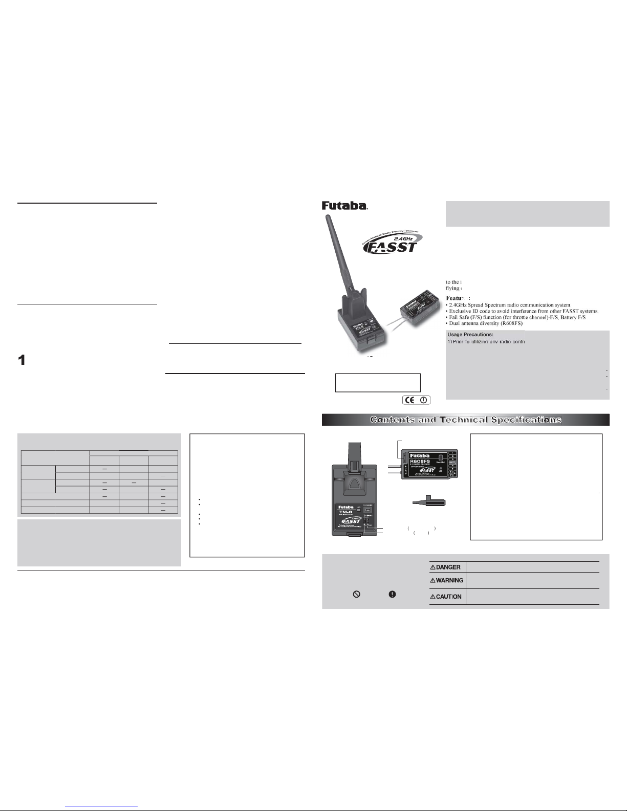
Easy Link
Each TM-8 transmitter module has an individually assigned
unique ID code. In order to start operation, the receiver must
be linked to the respective TM-8's ID code. Once the linking is
done, the ID code is stored in the receiver and the re-linking is
not necessary unless the receiver is to be used with a different
TM-8 module.
Additionally, it is important to note that this TM-8 and R608FS
receiver set has already been linked by the factory. Should
you wish to re-link them, or if you have purchased a separate
receiver and would like to link it to this TM-8, please adhere to
the following procedure.
nWARNING
jAfter the linking is done, please cycle receiver power
and check if the receiver to be linked is really under the
control by the transmitter to be linked.
lDo not perform the linking procedure with motor's main
wire is connected or the engine is operating as it may
result in serious injury.
1Ensure that the ch-mode select is set to the position
of the receiver's operation protocol. Please refer the
compatibility table in P4 for ch-mode select versus the
receiver to be paired.
2After the TM-8 module has been installed into the
transmitter, using the aforementioned steps, turn on
the transmitter. The green LED, located on the rear of the
TM-8 transmitter module, should begin to blink. If not,
power down the transmitter and turn it on once again.
3With the transmitter on, and the green LED blinking,
turn on the receiver.
4With the receiver on, press and hold the Easy Link
button, located on the receiver, for approximately
two seconds and release it. Then the receiver starts
linking procedure. When the linking process has been
completed, the LED on the receiver will change to a solid
green and the linking is established.
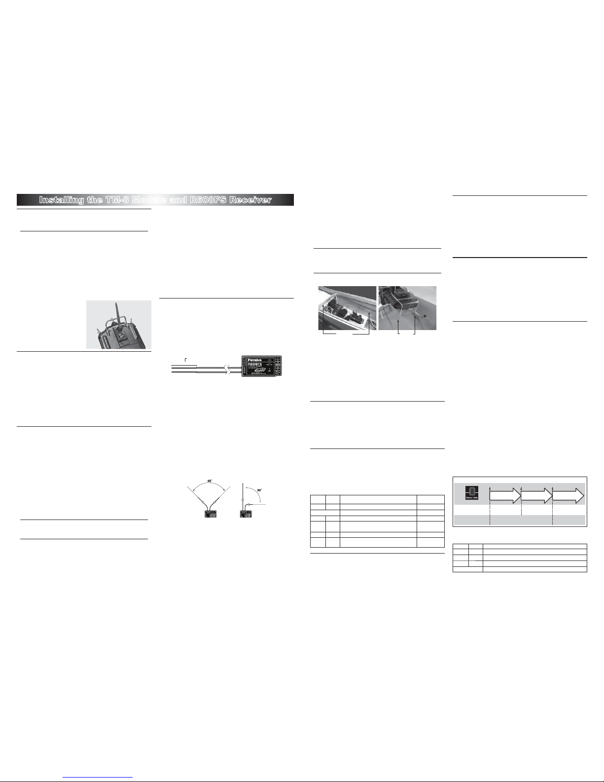
Receiver Installation
You will note that the R608FS differs in appearance from
the standard Futaba receiver. The R608FS incorporates two
separate antennas into its design which enables it to receive
the radio frequency transmission at two different locations.
Futaba's dual antenna diversity, or DAD, then seamlessly
selects the best signal reception between these antennas to
ensure that there is no loss of signal.
Antenna
*Must be kept as straight as possible.
Coaxial cable
To obtain the best results from the R608FS receiver, please
refer to the following instructions and precautions:
1Install the receiver in the aircraft using the same
methodology as you would handle a standard
receiver. That is, make sure that you wrap the receiver
in foam rubber or other such material to make it less
susceptible to vibration, etc.
2Ensure that the two receiver antennas are kept as
straight as possible. This will allow you to obtain the
maximum effective range from your model.
3If possible, please make sure that the two antennas
are placed at 90 degrees to each other. Please note:
This is not a critical figure, however, the most important
thing is to keep the antennas away from each other as
much as possible.
4If your model includes metal conductive items which
may impact the receiver's ability to clearly receive
the radio frequency signal, we suggest mounting the
receiver so that the receiver antennas exit both sides of
the model. This will allow the best radio frequency signal
condition at any flying attitude.
5Ensure that the antennas are at least 1/2" away from
any conductive materials such as metal and carbon.
Please note: this is not applicable to the coaxial portion
of the antenna. It is important, however, to not bend the
coax, or antenna in a tight radius.
6If the fuselage is made of conductive materials such
as metal and carbon, the antennas part MUST be
positioned so that they exit the fuselage. Additionally, do
not attach the antenna itself to this fuselage.
* For example, there are many types of gliders which use carbon fu-
selage. When install the receiver into such models, it is imperative
that the antenna precautions are adhered to strictly.
nWARNING
jBe very careful when handling the receiver antennas.
Repeated bending and flexing of the antennas or ex-
cessive force could weaken or compromise the internal an-
tenna connections.
jKeep the antennas away from the motor, ESC, and
other noise sources as much as possible.
Antenna Antenna
* The main purpose of the photo demonstrates how the antenna
should be placed. For actual installation the receiver must be
ZUDSSHGZLWKDVSRQJH RUSODFHGZLWK ÀRDWLQJPDWHULDOWRSURWHFW LW
from vibration.
* The receiver contains delicate electronic parts and should be pro-
tected from vibration, shock and temperature extremes.
* The receiver is not impervious to damage from moisture. If moisture
should enter the receiver, intermittent operation or failure may result.
To prevent this from occurring, we suggest wrapping the receiver in
a plastic bag or similar protective covering. This will also protect the
receiver from any fuel or exhaust residue which can work its way
into the fuselage.
Area select
The TM-8 transmitter module has been designed to function
in many countries. If you will be utilizing this module in a
country other than France, please make sure that the switch is
set to the "General" position. If, however, this module will be
utilized in France, the switch must be set to "France".
Operation of the TM-8
When the transmitter is powered up, the LEDs on the rear of
the module will begin to glow or blink accordingly. The chart
below provides you with an easy reference as to the meaning of
the LEDs.
LED indication
Green Red Status Fail safe (F/S)
Solid Solid Initializing (When Power Up) ---
Alternate blink Check RF condition nearby ---
Solid Off RF power on Off
Solid Blink RF power on (Power reduced to perform the
range check function) Off
Blink Off RF power on On
Blink Blink RF power on (Power reduced to perform the
range check function) On
F/S (Fail Safe) mode setting
The F/S is suggested for use as it offers a safety factor when
controlling your models. It is also possible to cancel the F/S
operation if you do not wish to use it.
De-activating the F/S (Failsafe)
As noted above, it is also possible to de-activate the failsafe
setting of the receiver.
Depress the F/S button on the rear of the transmitter
while turning the transmitter's power on. The LEDs
should begin to glow. Continue holding the button until
the green LED begins to glow solidly and the red LED
blinks.
Re-Arming the F/S (Failsafe)
To activate the failsafe once again, depress the F/S
button on the rear of the transmitter while turning the
transmitter's power on. The LEDs should begin to glow.
Continue holding the button until the green and Red
LED's begin blinking.
* Please note: re-arming the F/S does not alter the pre-determined
throttle servo position. To modify this setting, please follow the F/S
position setting procedure.
F/S position setting procedure
As mentioned at "Easy Link", the R608FS starts linking
process by press the Easy Link button more than two seconds.
Meanwhile, when linking is done, the R608FS stores
3ch(Throttle) position as the F/S position automatically. If you
need to change the F/S position but not need to re-link, set the
3ch(throttle) stick as desired position and press and hold the
Easy Link button just one second. By this way, the receiver
renew the F/S data for current 3ch position. Prior to doing
so, ensure that the F/S is active. If not, please follow the Re-
Arming of the F/S procedure as noted previously.
1With the transmitter's throttle stick in the desired
F/S position, and the receiver located within one
(1) meter of the transmitter, turn on the transmitter. The
green LED, located on the rear of the TM-8 transmitter
module, should begin to blink. If not, power down the
transmitter and turn it on once again.
2With the transmitter on, and the green LED blinking,
turn on the receiver. Press and hold the Easy Link
button, located on the receiver, for approximately one
second.
3
Turn off the transmitter. The throttle servo should
move to the pre-determined F/S position.
R608FS “F/S set” and “Easy-link” Operation
0 to 1 sec.1 to 2 sec.More than 2 sec.
0 sec.1 sec.2 sec.
Press and Hold time
No functionWith TM-8 To set the F/S
position(No re-link)
Re-link(ID set) and to
set the F/S position
No function
With TM-14
(not included in this set)
Re-link(ID set)
Please refer to the table below for the LED status of the
receiver's condition.
Green Red Status
Off Solid No signal reception
Solid Off Receiving signals
Blink Off Receiving signals but ID is unmatched
Alternate blink Unrecoverable failure (EEPROM, etc.)
Installing the TM-8 Module and R608FS Receiver
- 2 - - 3 -

This manual suits for next models

1

Other FUTABA Receiver manuals

FUTABA 2PL-FM User manual

FUTABA

FUTABA 2PL-FM User manual

FUTABA R2006GS User manual

FUTABA

FUTABA R2006GS User manual

FUTABA R6303SBE User manual

FUTABA

FUTABA R6303SBE User manual

FUTABA R204GF-E User manual

FUTABA

FUTABA R204GF-E User manual

FUTABA R3106GF User manual

FUTABA

FUTABA R3106GF User manual

FUTABA R2001SB User manual

FUTABA

FUTABA R2001SB User manual

FUTABA R6208SB User manual

FUTABA

FUTABA R6208SB User manual

FUTABA S.Bus 2 User manual

FUTABA

FUTABA S.Bus 2 User manual

FUTABA T-FHSS Air R3001SB User manual

FUTABA

FUTABA T-FHSS Air R3001SB User manual

FUTABA SKYPORT 6 User manual

FUTABA

FUTABA SKYPORT 6 User manual

FUTABA R404SBS-E User manual

FUTABA

FUTABA R404SBS-E User manual

FUTABA R7014SB User manual

FUTABA

FUTABA R7014SB User manual

FUTABA R304SB User manual

FUTABA

FUTABA R304SB User manual

FUTABA R404SBS User manual

FUTABA

FUTABA R404SBS User manual

FUTABA 4PM How to use

FUTABA

FUTABA 4PM How to use

FUTABA R6203SB User manual

FUTABA

FUTABA R6203SB User manual

FUTABA R404SBS-E User manual

FUTABA

FUTABA R404SBS-E User manual

FUTABA R6208SB User manual

FUTABA

FUTABA R6208SB User manual

FUTABA R314SB User manual

FUTABA

FUTABA R314SB User manual

FUTABA R607FS User manual

FUTABA

FUTABA R607FS User manual

FUTABA R6308SBT User manual

FUTABA

FUTABA R6308SBT User manual

FUTABA R2006GS User manual

FUTABA

FUTABA R2006GS User manual

FUTABA R7006SB User manual

FUTABA

FUTABA R7006SB User manual

FUTABA 4GRS User manual

FUTABA

FUTABA 4GRS User manual

Popular Receiver manuals by other brands

Raymer FM Receiver 840-35 operating instructions

Raymer

Raymer FM Receiver 840-35 operating instructions

Stageline txs-892 instruction manual

Stageline

Stageline txs-892 instruction manual

Onkyo TX-NR727 Firmware update guide

Onkyo

Onkyo TX-NR727 Firmware update guide

Alpha Micro NetPort user guide

Alpha Micro

Alpha Micro NetPort user guide

Denon ADV-M71 Specifications

Denon

Denon ADV-M71 Specifications

Pioneer SC-1523-K operating instructions

Pioneer

Pioneer SC-1523-K operating instructions

Grecom PSR-800 owner's manual

Grecom

Grecom PSR-800 owner's manual

Sirius Satellite Radio SportsterIR SPR2C user guide

Sirius Satellite Radio

Sirius Satellite Radio SportsterIR SPR2C user guide

Onkyo HT-R410 Service manual

Onkyo

Onkyo HT-R410 Service manual

Progres AgroBee-L manual

Progres

Progres AgroBee-L manual

FTE Maximal MAX S123 HD Quick installation guide

FTE Maximal

FTE Maximal MAX S123 HD Quick installation guide

AMG AMG4682-1550-C instruction manual

AMG

AMG AMG4682-1550-C instruction manual

Sensia True-Cut R Series user manual

Sensia

Sensia True-Cut R Series user manual

Harman Kardon AVR 330 owner's manual

Harman Kardon

Harman Kardon AVR 330 owner's manual

AMG AMG5516 instruction manual

AMG

AMG AMG5516 instruction manual

CHC P3DT user manual

CHC

CHC P3DT user manual

Gateway LN-520 operating instructions

Gateway

Gateway LN-520 operating instructions

Yamaha RXA830 Easy setup guide

Yamaha

Yamaha RXA830 Easy setup guide

manuals.online logo
manuals.online logoBrands
  • About & Mission
  • Contact us
  • Privacy Policy
  • Terms and Conditions

Copyright 2025 Manuals.Online. All Rights Reserved.