manuals.online logo
Brands
  1. Home
  2. •
  3. Brands
  4. •
  5. FUTABA
  6. •
  7. Remote Control
  8. •
  9. FUTABA T10J User manual

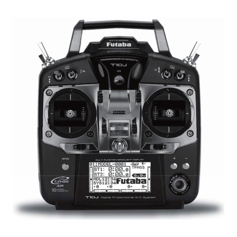
FUTABA T10J User manual

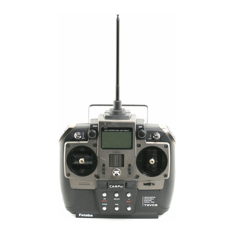
2 RotorDroneMag.com
Power Switch
All transmitters have a main power
switch for turning the radio on
and off. Some transmitters have a
program menu option to turn on with
or without the radio signal being
transmitted. is is helpful for setting
up your radio’s programming.
Control Trim Levers
Close to the control sticks, are small switches that may
be used to “trim,” or offset, the neutral position of each
of the control functions. ese trims adjust the center
neutral position of each control function (or the idle
position in the case of the throttle control) and allow
you to fine- tune your multirotor’s response. When the
control stick is centered but the model wants to drift
to the left or right or forward of backward, the trim
levers are used to bring the model back to a solid and
consistent hover.
Control Sticks
ere are two main control sticks. e left stick (mode 2 setup)
controls the power of the motors and the yaw response of the
quadcopter. If you were inside a cockpit, the left stick takes the place
of the throttle control and rudder pedals. e right control stick is like
the main control column or joystick that would be between your legs
in the cockpit. For an airplane, it controls the ailerons (roll) axis and
the elevator (pitch) axis. With a quadcopter, by moving the right stick
you control the left/right movement of the multirotor as well as the
forward/aft movement.
Main Display screen
This LCD screen is the window into your radio’s programming. It is where
you navigate to the various programming functions and options and
it also provides important information while you are operating your
multirotor. Basic information that is shown on the main screen includes
the model type, name and number, the transmitter battery voltage,
the type of signal modulation selected, user countdown or count-up
timers, and graphic bars to show the various trim lever positions. There
are several submenus also available for specific control functions and
programming parameters. There may also be a graphic for telemetry
receiving accuracy if your transmitter has that capability.
AnAtomy
of A RAdio
AN INSIDE LOOK AT HOW RC
TRANSMITTERS WORK
BY Gerry yarrish PHOTOS BY Pete hall
As you become more involved with multirotors and the
sophistication of your aerial vehicle increases, you will
get to a point where you will start using higher-quality
radio systems. Many multirotors
come with a dedicated transmitter
that’s programmed to work with
that rotordrone. For aircraft that
are built from kits or come in
almost ready to fly or bind and fly
packages, you’ll have to supply your
own transmitter. There are several
programmable radio systems
available and to demonstrate the
basics, we’ve chose the popular
10J radio system from Futaba. All
modern radio systems operate
on basically the same principles
and differ mostly with how their
programming menus are navigated.
Relatively simple in operation,
transmitters (and their internal
components) can be a little
intimidating for first-time user. This
overview explains what the main
parts are, where they’re found and
what the basic functions are.
January/February 2015 3
Antenna e antenna that transmits the radio signal to the multirotor can be
internally or externally mounted. Some newer transmitters have the antenna incorporated
into the transmitter’s handle. Depending on the radio’s systems, single or dual transmitter
antennas may be used.
On the insiDe
Inside the transmitter case are
the various circuit boards, wiring
and electronic items that transmit
the radio frequency, vary the signal
modulation that in turn controls the
multirotor, and if so equipped, receive
telemetry data from the multirotor.
Multi-FunctiOn switch
anD Key ButtOns
These are used to select and adjust the
various program menu items. By pressing or
by pressing and holding these buttons and
switches, you bring up the submenus for the
radios, function and system items. Each radio
system comes with a detailed instruction
manual describing each function and program
option in great detail. In the most basic form,
this is how you select the type of model
function you want, how you name the model
and how to set up your controls specifically
for the safe and precise control of your
multirotor.
Switches
Transmitters are equipped
with various two- and three-
position switches located at
the two upper corners of the
case. ese switches allow
you to change from various
settings, including dual rates
and exponential control as
well as auxiliary functions. You
can also activate various flight
modes and programmed mixes
between various controls.
Basic radios have fixed switch
functions with the switches
labeled to identify their
functions. More advanced radios
provide the flexibility to allow
you to assign various functions,
flight modes and mixes to the
switches you want.
Control Gimbals
e base of each control stick is
connected to a movable gimbal
assembly. ese spring-loaded
(except for throttle), self-
centering components read
the position of the control stick
and send that information to
the control board that, in turn,
determines the appropriate
control commands and sends
them out via the signal
modulation circuitry. Moving
the sticks changes the signals
transmitted to the airborne
receiver in the multirotor.
Circuit Boards
Divided in several main and sub
boards, the green PC boards are the
brains of the transmitter. All of the
integrated circuits, switches and wires are
connected to the PC boards. e boards
manage the power delivered to the radio’s
programmable EPROM, which is a type of
memory chip (shown at right) that retains its
data when its power supply is switched off.
In other words, it is non-volatile and it is the
integrated circuit that contains the settings that
the main display is used to program.
AnAtomy of A rAdio
4 RotorDroneMag.com
Airborne System
e little electronic box that “hears” the signal sent to it by the transmitter
is called the receiver. Its job is to receive the radio signal, translate it into the
desired flight commands, and then convert it back into the proper signals to
move the various servos and provide the rotors’ speed information to the flight
motors. Most of today’s RC radio systems operate on the 2.4GHz frequency
band and for the transmitter and receiver to work together, you have to “bind”
or link the receiver to your particular transmitter. Once this is done, the receiver
will only accept the specific coded signals sent to it by the linked transmitter.
is type of signal modulation
completely eliminates any change
of radio interference from other RC
transmitters operating in the same
area.
e receiver can be powered
by a separate battery pack or by
an electronic speed control that is
equipped with electronic circuitry
that provides power to the receiver
and servos from the main battery.
Sub-Menu
Screens
Once you enter the radio’s
programming menus, you can
call out and select several sub-
menus, where you can enter your
changes and selections. Some of
the basic sub-menus include those
for setting up the various servos
for control throw and direction as
well as sub-trims for fine-tuning
the center point of the servo.
You can also adjust control rates and the sensitivity around the center of the
control stick movements. ere are sub-menus for selecting the model type,
which gives you the choice of airplane, glider/sailplane, helicopter, and with the
Futaba 10J, multirotor programming. Like any other type of advanced electronic
device, programming your RC transmitter becomes easier with continued use
–- and watching multiple YouTube videos! With increased experience comes a
better understanding of what’s possible. K
transMitter case
On the back side of the
case there is the battery
compartment cover, the Trainer
“Buddy Box” connection jack,
a 3.5mm earphone plug for
listening to telemetry data
and an S.Bus connector for
advanced servo and telemetry
module setup.
Right: e main display shows you all the sub-menus so
you can make the required adjustments. Here you see
two of the specialty S.Bus receiver setting screens.
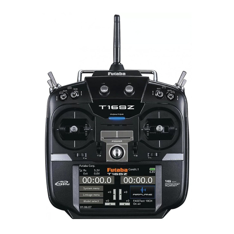
Below: ere are many brands of transmitter and
radio systems available with various options and with
different numbers of channels.
e receiver will only
accept the specific
coded signals sent
to it by its linked
transmitter.

Other manuals for T10J

2

Other FUTABA Remote Control manuals

FUTABA 9 CHP SUPER User manual

FUTABA

FUTABA 9 CHP SUPER User manual

FUTABA SKYSPORT 4YF User manual

FUTABA

FUTABA SKYSPORT 4YF User manual

FUTABA T6L SPORT User manual

FUTABA

FUTABA T6L SPORT User manual

FUTABA GYA460 User manual

FUTABA

FUTABA GYA460 User manual

FUTABA T4PM User manual

FUTABA

FUTABA T4PM User manual

FUTABA 2PL Owner's manual

FUTABA

FUTABA 2PL Owner's manual

FUTABA ATTACK_III User manual

FUTABA

FUTABA ATTACK_III User manual

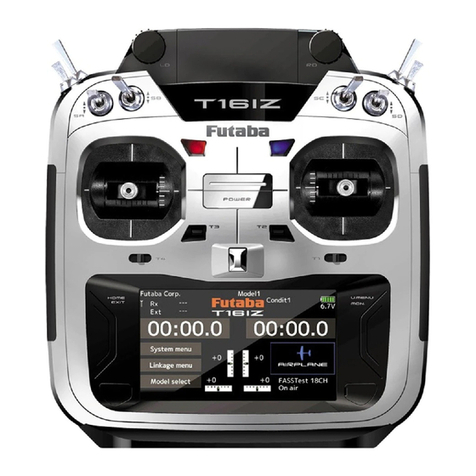
FUTABA T16IZ Ver.2 Manual

FUTABA

FUTABA T16IZ Ver.2 Manual

FUTABA T10J User manual

FUTABA

FUTABA T10J User manual

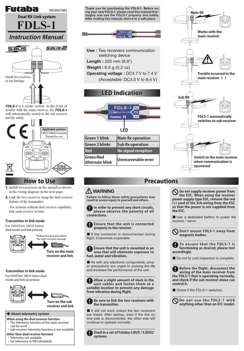
FUTABA FDLS-1 User manual

FUTABA

FUTABA FDLS-1 User manual

FUTABA R7314SB User manual

FUTABA

FUTABA R7314SB User manual

FUTABA T18MZ User manual

FUTABA

FUTABA T18MZ User manual

FUTABA FP-2PD User manual

FUTABA

FUTABA FP-2PD User manual

FUTABA 7C-2.4GHz User manual

FUTABA

FUTABA 7C-2.4GHz User manual

FUTABA 9ZAP - PART1 User manual

FUTABA

FUTABA 9ZAP - PART1 User manual

FUTABA 6k User manual

FUTABA

FUTABA 6k User manual

FUTABA T16IZ Manual

FUTABA

FUTABA T16IZ Manual

FUTABA 2PKA User manual

FUTABA

FUTABA 2PKA User manual

FUTABA 8UHPS User manual

FUTABA

FUTABA 8UHPS User manual

FUTABA Mega Tech 3PK User manual

FUTABA

FUTABA Mega Tech 3PK User manual

FUTABA 12Z Series User manual

FUTABA

FUTABA 12Z Series User manual

FUTABA FASST User manual

FUTABA

FUTABA FASST User manual

FUTABA T14SG Technical manual

FUTABA

FUTABA T14SG Technical manual

FUTABA 6YG-FM User manual

FUTABA

FUTABA 6YG-FM User manual

Popular Remote Control manuals by other brands

Gyration GP2100-001 features and benefits

Gyration

Gyration GP2100-001 features and benefits

Sveaverken Svea Agri X1201 user manual

Sveaverken Svea Agri

Sveaverken Svea Agri X1201 user manual

EAS Electric Gama EFSP instruction manual

EAS Electric

EAS Electric Gama EFSP instruction manual

Kaysun KCCHT-02 owner's manual

Kaysun

Kaysun KCCHT-02 owner's manual

Zenith SL-6037-WH - Heath - Wireless Command user guide

Zenith

Zenith SL-6037-WH - Heath - Wireless Command user guide

Wfly ET06 instruction manual

Wfly

Wfly ET06 instruction manual

Ashly WR-5E user manual

Ashly

Ashly WR-5E user manual

AERMEC WLRCA10 user manual

AERMEC

AERMEC WLRCA10 user manual

Kleinn Sniper quick guide

Kleinn

Kleinn Sniper quick guide

Flying Industry Development 0020794 user manual

Flying Industry Development

Flying Industry Development 0020794 user manual

Entone Nova user guide

Entone

Entone Nova user guide

CORNING Nano Power E62-N2RU installation manual

CORNING

CORNING Nano Power E62-N2RU installation manual

Midea RG57H(B)/BG(C)E owner's manual

Midea

Midea RG57H(B)/BG(C)E owner's manual

MrCool R 57A6/BGEFU1 user manual

MrCool

MrCool R 57A6/BGEFU1 user manual

VolantexRC EXMITTER EX6 user manual

VolantexRC

VolantexRC EXMITTER EX6 user manual

Schartec T6106 manual

Schartec

Schartec T6106 manual

Hunter 21117 Owner's guide and installation manual

Hunter

Hunter 21117 Owner's guide and installation manual

aldes EXHAUSTO InspirAIR Top VEX40T Assembly instructions

aldes

aldes EXHAUSTO InspirAIR Top VEX40T Assembly instructions

manuals.online logo
manuals.online logoBrands
  • About & Mission
  • Contact us
  • Privacy Policy
  • Terms and Conditions

Copyright 2025 Manuals.Online. All Rights Reserved.