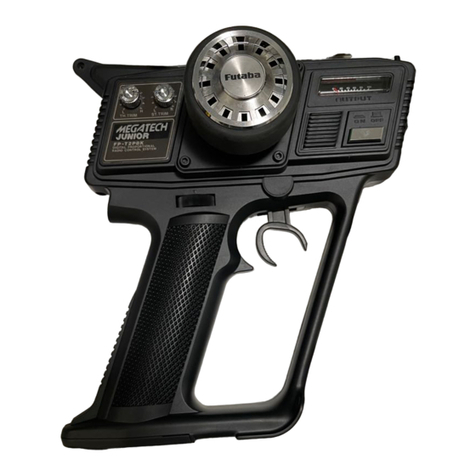
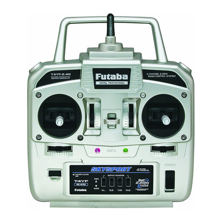
FUTABA FP-3FN User manual

FP-6FN6ch.FP-5FN 5ch.
FP-4FN4ch. FP-3FN3ch.

INDEX
Features
.....................................................................
Composition and Specifications
....................................
Transmitter
handling
instructions
....................................
Receiver
and
servo
handling instructions
........................
FUTABA trainer
system
................................................
Operating instructions
...................................................
Nickel-cadmium battery and charging methods
...............
Performancetestand mounting precautions.....................
FUTABA proportional
frequencies
.................................
Guarantee.....................................................................
Factory repair service
...................................................

FEATURES OF THE NEW FUTABA PROPORTIONAL
RADIO CONTROL SYSTEM
TRANSMITTER (FP—T6FN. FP—T5FN.FP—T4FN,FP—T3FN)
1.Since allFutaba New Proportional Models aredesigned and manufactured to identicalstandards,maximum
performance is displayed even when used withother receiversand servos.
2. Position of throttlecontrolcan beeasilychanged (to leftor right).
3.Hook band permits hanging the transmitterfrom your neck forextremelyeasy handling.
4.Training system provided as standard makes training of beginners easy.
5.Equipped with a stand.
RECEIVER (FP—R6F. FP—R4F, FP—R3F)
1.Newly developed receiver useFUTABA CUSTOM 1C(IR-014,orBA-633) isextremely stable against power supply
voltage fluctuations.
2.Eight-bit CMOS 1Chas complete 6-channel operation functions andreduces power consumption to a minimum.
3.Resistance against interference has beenstrengthened considerably through the adoption of a RFamplifier circuit
and ceramic filter.
SERVO (FP—S7. FP—S12. FP—S16. FP—S16L. FP—S17,andFP—S8, FP—S16G
[retractable landinggear servo])
1.Since the FP-S7, FP-S12, FP-S16, FP-S16L, FP-S17, and FP-S8, FP-S16G (retractablelanding gearservo)are
designed and manufacturedto the same standards, top performance is displayed when used withany NEW
FUTABAPROPORTIONALtransmitterandreceiver.
2.Three-wire, compact, lightweight, rugged, high-output torque servoamps have beenrealized through the useof
Futaba BA-607 and BA-606 custom monolithic 1C.
3.The BA-607 monolithic 1Cisa 12-pinsingle-end-line 1Ccontaining 73 transistors, 13diodes,and79 resistors (total
of 165components). Itslow current drain, high resolution, temperature compensation and built-in voltage regulator
assure stable operation over the4V—6.6V power supplyvoltage range without any mutual interference between
servos.A

4.The BA-606monolithic 1Cis a 9-pin single-end-line 1Cincorporating 2 high output current(500mA)
PNP
tran-
sistors,2 NPN transistors,4 diodes,and 4 resistorsfora totalof 12componentson a single chip.
5. High outputtorque: FP-S7; 3kg-cm,FP-S12; 2.8kg-cm,FP-S16 (S16L);2kg-cm,FP-S17; 2.6kg-cm,and FP-S8,
FP-S16G (retractablelanding gear servo);8kg-cm,2.6kg-cm.
6.Compact, lightweight: FP-S7; 48g,FP-S12; 52g,FP-S16 (S16L); 41g,FP-S17; 44g, and FP-S8; 50g, FP-S16G; 41g.
7. The 20mm(dia.) motor of the FP-S7 servoprovidespower torque. Thus making it ideal for
boat and automobile
use. Waterproofcasealsomakes itperfectfor use in both freshwaterand saltwaterareas.
8.FP-S12 is a low cost servo and powerful torque of 2.8kg-cmorgreater permits usenotonly inlarge buggies,
butalso inClass60 boats, etc.
9.The potentiometer drivesection of theFP-S16(S16L)isseparately driven through a one-stage gear. The life of
the element is almostpermanent.
10.FP-S17 is a lightweight,rugged, high output, and low cost servo.
11.The high gear ratio and powerfultorque of the FP-S8 make itthe perfect retractable landing gear servo.
12.FP-S16G isa highest class miniature landing gear servo.
COMPOSITION AND SPECIFICATIONS
•COMPOSITION:
Model
Number of channels
Transmitter
Receiver
Servo
Batterycharger
Transmitter/receivernickel-cadmium battery
PP-6FN
6CH
FP-T6FN
FP-R6F
FP-S16 x 3
FP-S16Lx1
Nickel-cadmium charger FBC—2(F)
FP-5FN
5CH
FP-T5FN
FP-S16x3
FP-S16Lx1
FP-4FN
4CH
FP-T4FN
FP-R4F
FP-S16x3
FP-S16Lx1
FP-3PN
3CH
FP-T3FN
FP-R3F
(FP-S7 x 2
FP-S16x 2 FP-S12x2
FP-S17x 2)

•
SPECIFICATIONS:
(All
specifications
are
subject
to change
without
prior
notice.)
TRANSMITTER
Operatingsystem.........CH1—4, 2-stick system,CH5snap
switch,CH6trimleversystem
Operatingfrequencies...27MHz band 72MHz band
40MHz band
Antennaoutput............
500mW
Modulation
system
......
AM
(amplitude
modulation)
Pulsepositionmodulation:
1310uSneutral (Pulse spacing)
Powerrequirement......
9.6V 8/450mAH nickel-cadmium
battery
Current
drain...............
140mA
RECEIVER
Receivingfrequencies... 27MHz band72MHz band
40MHz band
IFamplifierfrequency...455kHz
Selectivity
..................
3kHz/-3dB
Range
........................
500m
on
the
ground,
1000m
intheair
Powerrequirement......4.8V 4/450mAH nickel-cadmium
battery
Current
drain...............
4.8V 10mA
Dimensions
...............
FP-R6F:
40
x69
x19mm
FP-R4F,
R3F:
40.2x58.5
x19mm
Weight........................
FP-R6F:
52g
FP-R4F.R3F:46g
SERVO (FP-S7, FP-S12, FP-S16,FP-S16L,
FP-S17,FP-S8, FP-S16G)
Control
system
............
3-wire,
+
pulse
widthcontrol
650uS~ 1900uS
Operating angle............
Rotary system one side 45° min
(including trim)FP-S7. FP-S12,
FP-S16.
FP-S17
Rotary system oneside 80° minFP-S8.
FP-S16G(retractablelandinggearservo)
Powerrequirement......4.8V 4/450mAH nickel-cadmium battery
(usedinconjunctionwith receiver)
Current
drain...............
4.8V
8mA
(when
stopped)
Output torque............
FP-S7; 3kg-cm,FP-S12: 2.8 kg-cm,
FP-S16; 2kg-cm,FP-S17: 2.6kg-cm,
FP-S8: 8kg-cm,FP-S16G: 2.6kg-cm.
Dimensions.................. FP-S7:
23 x 44 x 41mm.
FP-S12:23 x 44.5 x 42.5 mm,
FP-S16:19.5x415x35.5mm,
FP-S17:20 x 39.6 x 40 mm,
FP-S8;23x44x41mm,
FP-S16G: 19.5x 41.5 x 35.5 mm
Weight........................
FP-S7:
48g,
FP-S12;
52g,
FP-S16;
41g,
FP-S17;44g.FP-S8: 50g, FP-S16G;41g.
BATTERY CHARGER (Nickel-cadmiumcharger)
Input
voltage
...............
115V
(220V,
240V)
Frequency
..................
50/60Hz
Power consumption ...2.0/3.5VA
Output
Tx.
..................
9.6V, 45mA
Output
Rx................... 4.8V, 45mA
NOTE:
Power consumption is for noload/load. Since the transformer may beburned upor the performances of the battery will deteriorate dueto
an
overcurreni ifthe NR-4C nickel-cadmium batteryis connected to the Tx output terminals, alwaysbesure that connections are correct.

TRANSMITTER HANDLING INSTRUCTIONS
FPT6FN
(forFP-6FN)
6CHANNEL
FP-T5FN
(tor
FP-5FN)
5-CHANNEL
FP-T4FN
(for
FP
4FN)
4-CHANNEL
FP-T3FN
(forFP-3FN)
3-CHANNEL
Fig.
1

Thecontrols onthe front panelof thetransmitterare shown in
Fig.2. The manipulationof these controlsshouldbethoroughly
mastered.
FP-T4FN (FP-T3FN)
The (1) engine, (2) ailerons, (3) elevator,
and(4)*rudder canbecontrolled with the
sticks at the left and right.
Transfer between transmittersispossible
with (5) trainer switchby connecting to
another transmitter with the trainer cord.
*FP-T3FN doesn't have (4)rudderabove.
FP-T5FN
Thelanding gear orothersuitableoper-
ations can beperformed by means of the
snap switch, inaddition to the 4 operations
mentioned above.
PP-T6FN
The flaps, etc. can beoperated bymeans
of a potentiometer, inaddition to the 5
operationsdescribed above.
•Select either the longor short left and
rightstick knob,whichever isthe easiest
touse.
The knob can bereplaced by merely pull-
ingoff the black knob.
•Hooktheneckstrap to the hookandhang
thetransmitter from your neck.
Fig.
2
Trainercordsocket
AUX Lever
(6THCHANNEL)
FP-T6FN
Aileron
Rudder
Throttle
(MODE1:Elevator)
Snapswitch
(5TH CHANNEL)
Trainerswitch
Elevator
(MODEL Throttle)
Servo rotates in
theforward direction
when movedinthe
direction of thethick
arrow (*).
NORMAL

1.The
FP-3FN,FP-4FN,FP-5FN, FP-6FN each usea built-innickel-cadmium battery (8/450 mAH) as the transmitter
powersource.
2. Mount the antenna securely and set the power switchto the ONposition . The pointer of the meter will deflect
to within the green zone. This indicates thatthe radiowavesarebeing radiated. Ifthe meter pointer fails
to
deflect, check for a faulty connection inthepower supply.
3.Ifthe meter pointerdeflects to within the red zone, the nickel-cadmium batteryislow and must bere-
charged. A special charger isprovided.
4.Notethat the range of the radio waves will become shorter when the meter pointerdeflects to within red zone.
5.The "trim" lever of each stickis usedfor fine adjustment. These levers are usedforneutraladjustment of each
rudder and to adjust the flyingposture aftermounting inthe fuselage.
6.Open the stand at the rear cover when setting upthe transmitter. This stand can beusedas a handle by
raising itto the topmost position. This is extremelyconvenient when carrying the transmitter.

RECEIVER AND SERVO HANDLING INSTRUCTIONS
1.The FP-R6F receiver employs an 8 bit 1Cand has beenespecially designed for 6 channeluse.(Combined 5
channel, 6 channel use.)
2.The block connectors which connect the receiver to each servo form a single unit with the receiver.
3.Connect to the servosby verifyingthe block connectorconnection positions stamped on the receiver case.Use
the white relayconnector for the ailerons. Besure to use the 3P white connector fromthe switchharness for
the power supply (BATT).
XTAL ...Crystal
AUX2... For6CHTx: Snap switch
AUX1...For6CH Tx: Lever type switch
For 5CHTx: Snapswitch
RUDD...Rudder(FP-3FNdoesn'thave
rudder)
ELEV ...Elevator
THRO ...Throttle
AILE ...Aileron
8ATT ...Powersupply
(FP-3FNdoesn't
have rudder)
Fig.
3
RED
FP-R6F
WHITE

4.Sinceall the servos are manufactured to thesame standards, any servo can beusedfor any purpose.
5.The FP-S6L (reversible servo, red label) inthe set can beconveniently used for throttle control with highwing
andmiddlewing airframes.
6.Connection methods areillustratedinFigure 3. Be sure thateachconnector is pluggedinfully andthat the
power supply switchharness, aileron section, etc. are connected correctly.
7.Afterverifyingthatall connections are correctby checking them against the connections given inFigure 3,turn
the transmitterpower switchon. Then turn the receiverswitchon. Atthistime, each servowillstop at the
neutral position.
8.Operate sticks andtrim levers andverify that respective servos operate positively.
9.When testing each section,besure that the transmitter andreceiver antennas are fully extended. Ifthe trans-
mitter antenna is short and the power switch isleftonfor more than 5 minutes,the transistors inside the
transmitter willbedamaged.
10.
Ifthe systemfailstooperate afterthe transmitter, receiver,servos, switch harness, and batteries have been
properly installed, the problem may bedue to damage during shipment.Donot attempttoopen any of the
unit,butreturn them for replacement.

FUTABA TRAINER SYSTEM
•The
NEW FUTABA PROPORTIONAL
Transmitters
FP-T4FN.
FP-T5FN,
and
FP-T6FN
are
equipped
with
the
newly developed FUTABA TrainerSystem as standard.Thissystem preventsdamaging of valuable aircraftby
beginners. Usethis system with a veteran as your teacher. A special trainer cord isavailable as anoption.
•The FUTABA Trainer System can beused without regard to frequency (27MHz, 40MHz, 72MHz) ornumberof
channelsof the instructor'stransmitterand studentstransmitter.For instance,the27MHz FP-T6FN canbe
usedwith the 72 MHz FP-T4FN. However, inthis case, use the 27MHzFP-T6FN as the instructor'strans-
mitter if the frequency of the receiver is 27MHz and use the 72MHz FP-T4FNas the instructor'stransmitterif
the frequency of thereceiveris 72MHz. Naturally,thenumber of operable channels corresponds to thatof the
transmitter. The aboveis an example of 4 channel operation.
OPERATING INSTRUCTIONS
1.When conducting training, connect the two transmitters together with the special cord*as illustrated inFigure 4.
*Similar cords are onsale,butsince these cannot beused,always usethe special FUTABA shielded trainer
cord.
2.The instructor must use a transmitter of the same bandas the receiver. (The instructor's transmitter isdesig-
nated
Tx1and thestudent'stransmitteris designated Tx2.)
Since the radio wavesare alwaysradiatedfromtheTx1side (transmitterwhose power has been turned on),
extend the antenna of Tx1 fully.The position of the antenna of Tx2doesn't matter, since the radio waves are
radiated from Tx1even when operationis performed from Tx2.
3.Turnonthe powerof Tx1 only. The meter pointer will deflect, the same as for the case of independentoperation.
The meter pointer of Tx2will also deflect simultaneously.
NOTE: Never turn the power switch of Tx2on,regardless of whether the bands coincide ornot.

4.When the trainer button of Tx1 isdepressed,
radiowaves will bedirectly radiated from
Tx1,butthe control operation isshifted to
Tx2.Consequently, the student canexercise
control only during the period the instructor
isdepressingthetrainer button.Whenthe
instructor releases the button,hecan exer-
cise directcontrol over all operations.
5.Performneutraladjustmentofthe other
transmitter onthe ground before beginning
actualflight.Adjustthe trimof both trans-
mitters so that the rudder servos are not
operated when the trainer buttonisde-
pressed.
6.Since power issupplied from Tx1 even when
the student isoperating, the current drain of
Tx1 will beabout 10%greater than when
usedindependently.
7.Deflection of the meter willbecome small
when the trainer cord isconnected, butthis
isnormal.
Switch ON
Tx1(Instructorside:Transmitter combinedwith receiver.)
Tx2 (Student side)
Fig.
4
Trainer switch
Instructor
Transmitter
StudentTransmitter
Switch
OFF
Trainer cord socket
Special trainer cord

NICKEL-CADMIUM BATTERY AND CHARGING METHODS
•TheFP-T3FN, FP-T4FN, FP-T5FN, and FP-T6FN transmitters are each equippedwith a built-innickel-cadmium
battery (8/450 mAH) power supply.
•Usea nickel-cadmium penlight cell (4/450mAH) as the receiver and servo power supply.
•Charge the nickel-cadmium batteryfor 12~15hours before normal use. Charge the battery for 20 hourswhen
ithas notbeused for an extended period of time. Slightovercharging will cause noharm tothe battery.
•A fully charged nickel-cadmium batterycan normally beusedabout10times at a 10minutes/time rate.
•The nickel-cadmium batterywillsupply a uniform voltage for a certain periodof time,butpaycareful attention
to the voltage afterbeingused 7~8 times.
Connect the battery charger supplied with theFP-3FN,FP-4FN,FP-5FN,andFP-6FNas illustratedinFigure5.
Fig.
5
AC-115V (220V, 240
FBC-2(F)
Tx
Rx
NR-4C

Receiver
WHITE
NiCdBattery
Charging plug
Charger(RX)
The3Predfemale connector of the switch harness isusedto charge theNR-4C (receiver and servo useNiCd
battery) without removing itfrom the model.
To
charge the NR-4C (receiverand servo NiCd battery)withoutremovingit fromthe model, set the switchto
the OFF position and connect the 3Pred male connector fromthe charger to the 3P red femaleconnector of
the switch harness.

1.The cord withthe power plug at both ends is the Tx charging usecord. Tocharge thetransmitter,connect
this cord to Txof the charger and "A" of the transmitter.
2.The cord with the power plugat oneendand the 3P connector at the other end isthe RX charging usecord.
When charging the NR-4C receiver use nickel-cadmiumbattery, connect the power plug end of this cordto
RX of the charger andthe 3P connector endto the NR-4C.
3.Plugthe charger plugintoan AC linereceptacle (AC 115V,220V,240V).
4.Charging is performed with the above operations. Atthis time,the LEDof thechargerwillbeilluminatedto
indicate thatchargingis being performed.
5.Beabsolutely surethat allthe connections arecorrect. Ifthe NR-4C receiverusenickel-cadmiumbattery is
connected to Tx, the battery may bedamaged by overcharging.
6.The special charger can charge the transmitter battery andreceiver battery simultaneously orindependently.
PERFORMANCE TEST AND MOUNTING PRECAUTIONS
1.Verifythatthe receiverand servos areconnected inaccordance withFigure 3.Then, make the transmitter
antenna
as
short
as
possible and
extend
the receiver antenna and attemptoperation
from
a
distance of
20m~
30m. Operation is normal if all the controlsare functioning properly. Perform this test within a maximum of
5minutes time. Never perform this testwhen the transmitter antenna isnotmounted to the transmitter. Other-
wise the transmitterwillbeadverselyeffected.
2. Becareful that the receiver doesnotdirectly touch other mechanisms of the aircraft itself. Moreover,wrap the
receiver insponge rubber so thatit is not subjected directlyto engine vibrations.(Inthe case of boat use,cover
the sponge wrapping witha vinylbag and tiesecurely at the point at which the cord enters sothatnowater can
enter the receiver.)

3.The useof a servo trayisextremelyconvenient wheninstallingthe servos.The method of installationis
illustrated inthe figure. (Insert each connectorfully.)Don't forgetto confirm thatthe motion of the servohorns
and rods matches the direction of operation of thetransmittersticks.Usethe reversible servo (Lservo) as a
shoulder wing throttleservoor for rudder and nose gearoperation.
•NOTE; The L servo cannot beused foraileroncontrol.(The operation of the stick andrudderare opposite.)
Fig.
6
TYPE"H"
TYPE"V
STICKTO RIGHT
Pig.
7
NORMAL
(TOCOUTER-
CLOCKWISE]
REVERSE
(TO CLOCKWISE)
2.3»18
2.6x6

4.After settingthepushrodat each servo,operate each servo fully leftandrightat least once.Iftherodcatches
orsticks at thistime, theservo hasbeendamaged byan overcurrent.Thereforeverify thattherodsare
functioning perfectly.
5.Beespecially careful ofnoisesignals.Forinstance,noisesignalswillbegenerated bythecontact of metal
against metal due to enginevibration. Ifthesenoisesignals are received at the receiver, the receiver may operate
erroneously. Therefore cover one of the metal surfaces with insulating material.
6.After installation iscomplete, ask a nearby radio control expert orthe dealer where the equipment was purchased
to instruct you ontheproperhandlingtechniques andother items which may requirespecialattention.Also
have your installation thoroughly checked at this time.
Strict observance of safety rulesandadherence to theadviseofexperts willmake radiocontrolmoreenjoyable.
FUTABAPROPORTIONAL FREQUENCIES
(Available inMHz. Available Futabapaircrystal Tx/Rx)
27 MHzAreas
26.995(Brown)
27.045
(Red)
27.095 (Orange)
27.145 (Yellow)
27.195 (Green)
72 MHzAreas
•72.080(Brown/White)
72.160 (Blue/White)
•72.240 (Red/White)
72.320 (Violet/White)
•72.400(Orange/White)
72.960 (Yellow/White)
•75.640 (Green/White)
Remarks: Mark * —ModelAircraft useonly.

GUARANTEE
YourNEWFUTABA Digital Proportional R/C system isguaranteed against de-
fects inworkmanship and material for 180days from the date ofpurchase when
the attached registration card isreturned to uswithin tendays of purchase.
This Guarantee isnullandvoid ifthe R/C system hasbeenimproperly handled,
damaged ina crash, ortampered with and does notcover the replacement of
plastic housings orelectronic components damaged due to theuseof improper
voltages.
When service isrequired, please take your equipmentto your localauthorized
service station orship itdirectly to us.All postage,shipping,and insurance
charges must bepaid bythe user.
This guarantee only applies to the continental U.S.A., Hawaii,andAlaska.

FACTORY REPAIR SERVICE
Toinsureprompt service, please follow the instructions given below.
1.Charge the batteries for at least 18hours priorto shipment.
2. Return the system, only. Notyour complete installation.
Remove the servos from theirmounts and
remove the foam padding fromthe receiver.
3.Plugsor other modifications which interfere with factory test procedures will bereturned to factory
standard atyour expense.
4.Carefullypack allcomponents individually,usingsufficient packing material to prevent damage
during shipment.
5. Include a brief but thoroughexplanationof allproblems and servicerequiredand tape itto the
back of the transmitter.Place a label describing the functionsof theservoon each servo.
6.Besure to include your full addressand zip code inside the box as wellas on theoutside.
7. Include a packing list of all itemsbeingreturned,anddoublecheck to make sure that allitems
are packed.
8.Uponreceipt of damaged equipment at the FUTABA factory, an estimate of the cost of repair will be
sent to you. Your equipment will then berepaired andreturned to you uponreceipt of payment.
Thisfactory repair service applies only to the continental U.S.A., Hawaii, and Alaska.

FUTABA
CORPORATION
OF
AMERICA
630CAROB
STREET,
COMPTON
CALIFORNIA
90220
U.S.A.
Phone:
(213)537-9610
•
FUTABA
CORPORATION
TokyoOffice:Daido
Bldg.
3-1-6
I
16,
Sotokanda.
Chiyoda ku.
Tokyo.
Japan
Phone:(03)255-5881 Telex:J26532
PrintedinJapan781020 cc
This manual suits for next models
17
Table of contents
Other FUTABA Remote Control manuals

FUTABA
FUTABA SBC-1 User manual

FUTABA
FUTABA 6EXP User manual

FUTABA
FUTABA T16IZ User manual

FUTABA
FUTABA FP-3EG User manual

FUTABA
FUTABA 2HR User manual

FUTABA
FUTABA 9ZAP - PART2 User manual

FUTABA
FUTABA 9 CHP SUPER User manual

FUTABA
FUTABA 4VF-FM User manual

FUTABA
FUTABA FP-5NLP User manual

FUTABA
FUTABA 6XA User manual

FUTABA
FUTABA 3PM-X 2.4GHZ User manual

FUTABA
FUTABA 6EXAP User manual

FUTABA
FUTABA FP-8SSHP User manual

FUTABA
FUTABA 6k User manual

FUTABA
FUTABA T16IZ Installation and user guide

FUTABA
FUTABA T8J-2.4G User manual

FUTABA
FUTABA R7314SB User manual

FUTABA
FUTABA SKYSPORT 2FR User manual

FUTABA
FUTABA FP-2PB User manual

FUTABA
FUTABA 9z Installation guide