FutureLogic GEN3 Evolution User manual

English (US)
Operators and Technicians Manual
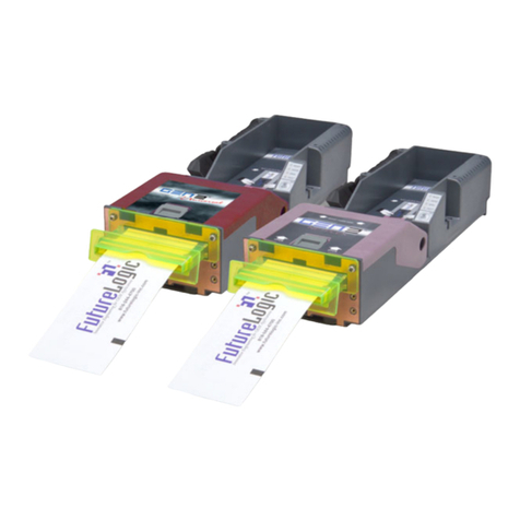
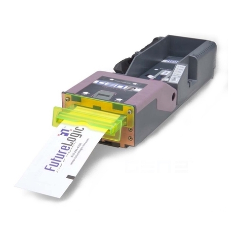
GEN3 Evolution® Printer
PSA-66-ST3 (RS232/USB)
While PSA-66-ST3 refers to all models of the printer, this manual is primarily for the RS232/USB interface of
the GEN3 Evolution printer.

FutureLogic, Inc. •425 East Colorado Street •Suite 100 •Glendale, CA 91205 USA
Phone 818.244.4700 •Fax 818.244.4764 •www.futurelogic-inc.com •info@futurelogic-inc.com
Operators and Technicians Manual
GEN3 Evolution® Printer (PSA-66-ST3 (RS232/USB))
2011 – 2014 FutureLogic, Incorporated. All Rights Reserved.
GEN3, Evolution, TCL, ITH, TCL Editor, FLDFU, CommWrangler, FutureLogic Exchange, and FutureLogic are either
trademarks or registered trademarks of FutureLogic, Incorporated in the United States and/or other countries.
Additional trademarks and intellectual property rights are listed on www.futurelogic-inc.com. All other trademarks and
products or brand names mentioned herein are the property of their respective owners.
This document contains Proprietary and Confidential information. Contents are covered by Non-Disclosure Agreement.
This document describes product functions and technology that may not be available in a particular gaming
jurisdiction, and would therefore not be available for sale and not approved for use at this time. Please contact your
local sales representative for information concerning what features are available in your jurisdiction.
This manual, as well as any software described in it, is furnished under license and may be used or copied only in
accordance with the terms of such license. Except as permitted by such license, no part of this manual may be
reproduced, stored in a retrieval system, or transmitted, in any form or by any means, electronic, mechanical, recording,
or otherwise, without the prior written permission of FutureLogic, Incorporated. The content of this manual including
technical information is disclosed and furnished for informational use only, is subject to change without notice, and
should not be construed as a commitment by FutureLogic, Incorporated. FutureLogic, Incorporated assumes no
responsibility or liability for any errors or inaccuracies that may appear in this manual and/or software. No grant of
license or use rights of any such information is made by publication or distribution of this manual.
The information in this manual and/or software described is distributed on an “As Is” basis, without warranty. While
every precaution has been taken in the preparation of this book and/or software, FutureLogic, Incorporated shall not
have any liability to any person or entity with respect to any loss or damage caused or alleged to be caused directly or
indirectly by the instructions and/or information contained in this manual or by the computer software and/or
hardware products described in it.
FUTURELOGIC, INCORPORATED (“FUTURELOGIC”) MAKES NO WARRANTIES, EXPRESS OR IMPLIED, INCLUDING
WITHOUT LIMITATION THE IMPLIED WARRANTIES OF MERCHANTABILITY AND FITNESS FOR A PARTICULAR PURPOSE,
REGARDING THE FUTURELOGIC SOFTWARE. FUTURELOGIC DOES NOT WARRANT, GUARANTEE, OR MAKE ANY
REPRESENTATIONS REGARDING THE USE OR THE RESULTS OF THE USE OF THE FUTURELOGIC SOFTWARE IN TERMS OF
ITS CORRECTNESS, ACCURACY, RELIABILITY, CURRENTNESS, OR OTHERWISE. THE ENTIRE RISK AS TO THE RESULTS AND
PERFORMANCE OF THE FUTURELOGIC SOFTWARE IS ASSUMED BY YOU. THE EXCLUSION OF IMPLIED WARRANTIES IS
NOT PERMITTED BY SOME STATES. THE ABOVE EXCLUSION MAY NOT APPLY TO YOU.
IN NO EVENT WILL FUTURELOGIC, ITS DIRECTORS, OFFICERS, EMPLOYEES, OR AGENTS BE LIABLE TO YOU FOR ANY
CONSEQUENTIAL, INCIDENTAL, OR INDIRECT DAMAGES (INCLUDING DAMAGES FOR LOSS OF BUSINESS PROFITS,
BUSINESS INTERRUPTION, LOSS OF BUSINESS INFORMATION, AND THE LIKE) ARISING OUT OF THE USE OR INABILITY TO
USE THE FUTURELOGIC SOFTWARE EVEN IF FUTURELOGIC HAS BEEN ADVISED OF THE POSSIBILITY OF SUCH DAMAGES.
BECAUSE SOME STATES DO NOT ALLOW THE EXCLUSION OR LIMITATION OF LIABILITY FOR CONSEQUENTIAL OR
INCIDENTAL DAMAGES, THE ABOVE LIMITATIONS MAY NOT APPLY TO YOU.
These specifications are subject to change without notice and may not completely and correctly document the
operation of this product.
04/10/2014
MNL-000067
REV.X03
Operators and Technicians Manual
2011 – 2014 FutureLogic, Incorporated. All Rights Reserved. MNL Page i04/10/2014
MNL-000067 REV.X03
Table of Contents
1Manual Overview.........................................................................................1
Introduction ...........................................................................................................................................1
Applicability ...........................................................................................................................................1
Intended Audience................................................................................................................................1
Conventions ...........................................................................................................................................1
2Product Overview ........................................................................................2
Introduction ...........................................................................................................................................2
Technical Support..................................................................................................................................2
Warranty Information...........................................................................................................................2
3Standard Operation.....................................................................................3
Introduction ...........................................................................................................................................3
Product View..........................................................................................................................................3
Bezel Light.......................................................................................................................................3
LEDs/Status Lights............................................................................................................................4
Ticket and Print Head Release Levers...................................................................................................4
Load Tickets............................................................................................................................................4
Clear a Ticket Jam..................................................................................................................................6
4Maintenance & Service................................................................................7
Introduction ...........................................................................................................................................7
Printer Sensors .......................................................................................................................................7
Remove the Printer for Servicing Outside of Game............................................................................8
Replace the Printer in a Game..............................................................................................................9
Printer Cleaning.....................................................................................................................................9
Cleaning Kits....................................................................................................................................9
Procedure.........................................................................................................................................9
5Ports and Cables ........................................................................................11
Introduction .........................................................................................................................................11
Firmware Upload Port.........................................................................................................................11
Front Bezel Port ...................................................................................................................................11
USB/RS232 Interface Cable..................................................................................................................12
RS232 Evaluation Cable.......................................................................................................................13
GDS Adapter Cable..............................................................................................................................14
6Configuration Tickets ................................................................................15
Introduction .........................................................................................................................................15
Overview...............................................................................................................................................15
Print Standard Configuration Ticket..................................................................................................15
Print Extended Configuration Ticket..................................................................................................15
Detailed Description............................................................................................................................16
Firmware Version ..........................................................................................................................16
Printer Serial Number ...................................................................................................................16
Comm Setup ..................................................................................................................................16
Print Control Parameters..............................................................................................................16
Reserved Flash Memory ................................................................................................................16
Library Inventory...........................................................................................................................16

Operators and Technicians Manual
2011 – 2014 FutureLogic, Incorporated. All Rights Reserved. MNL Page ii 04/10/2014
MNL-000067 REV.X03
7Memory/LED Module .................................................................................17
Introduction .........................................................................................................................................17
Overview...............................................................................................................................................17
Set the Printer Communication ..........................................................................................................18
COMM Switch Examples......................................................................................................................19
Remove the Memory/LED Module......................................................................................................19
8Firmware Upgrade.....................................................................................20
Introduction .........................................................................................................................................20
Method 1: Firmware Upgrade using USB Plug-in (Recommended).................................................20
Overview........................................................................................................................................20
Procedure.......................................................................................................................................21
Method 2: Firmware Upgrade using FLDFU Program.......................................................................22
Overview........................................................................................................................................22
FLDFU and Driver Installation (First Time)...................................................................................22
Procedure: Firmware Upgrade.....................................................................................................25
Method 2 Troubleshooting ..........................................................................................................27
9Functional Testing with CommWrangler™ ..............................................28
Introduction .........................................................................................................................................28
Connection and Setup.........................................................................................................................28
Option 1: USB CDC Connection (Install a Virtual COM Port) .....................................................28
Option 2: Serial Connection .........................................................................................................30
CommWrangler....................................................................................................................................31
Procedure: Initialize Communications.........................................................................................31
Procedure: Print Test Tickets ........................................................................................................32
10 Troubleshooting.........................................................................................33
Introduction .........................................................................................................................................33
Printer Troubleshooting......................................................................................................................33
Printer Errors........................................................................................................................................34
Appendix A Technical Specifications...........................................................35
Introduction .........................................................................................................................................35
Printer Specifications...........................................................................................................................35
Ticket/Paper Specifications..................................................................................................................37
Appendix B Part Numbers............................................................................38
Introduction .........................................................................................................................................38
Printer...................................................................................................................................................38
Evaluation Kit.......................................................................................................................................38
Accessories: Bezels ...............................................................................................................................39
Accessories: LED PCBs ..........................................................................................................................43
Accessories: Other................................................................................................................................43
Parts......................................................................................................................................................44
Appendix C Exploded View..........................................................................47
Appendix D Schematics................................................................................49
Introduction .........................................................................................................................................49
Index .............................................................................................................56

Operators and Technicians Manual
2011 – 2014 FutureLogic, Incorporated. All Rights Reserved. MNL Page iii 04/10/2014
MNL-000067 REV.X03
List of Figures
Figure 3-1 GEN3 Evolution Printer Components................................................................................3
Figure 3-2 Ticket and Print Head Release Levers ...............................................................................4
Figure 3-3 Pull Printer Forward...........................................................................................................4
Figure 3-4 Fan Paper............................................................................................................................5
Figure 3-5 Load Ticket Stack................................................................................................................5
Figure 3-6 Lid Release Lever and Ticket In Slot..................................................................................6
Figure 3-7 Print Head Release Lever...................................................................................................6
Figure 4-1 Printer Sensors....................................................................................................................7
Figure 4-2 Pull Printer Forward...........................................................................................................8
Figure 4-3 Disconnect Interface Cable Connector .............................................................................8
Figure 4-4 Pull and Hold Release Slide ...............................................................................................8
Figure 4-5 Printer Cleaning Kit............................................................................................................9
Figure 4-6 Pull Print Head Release Lever............................................................................................9
Figure 4-7 Clean Print Head ..............................................................................................................10
Figure 4-8 Clean Sensors....................................................................................................................10
Figure 4-9 Clean Rollers.....................................................................................................................10
Figure 5-1 Firmware Upload Port......................................................................................................11
Figure 5-2 Front Bezel Port................................................................................................................11
Figure 5-3 USB/RS232 Interface Cable...............................................................................................12
Figure 5-4 RS232 Evaluation Cable ...................................................................................................13
Figure 5-5 GDS Adapter Cable ..........................................................................................................14
Figure 6-1 Configuration Tickets.......................................................................................................15
Figure 7-1 Memory/LED Module.......................................................................................................17
Figure 7-2 Memory/LED Module Screws...........................................................................................19
Figure 7-3 Pull Out Module...............................................................................................................19
Figure 8-1 Plug Adapter Cable into Firmware Upload Port............................................................21
Figure 8-2 InstallShield Wizard .........................................................................................................23
Figure 8-3 Device Manager ...............................................................................................................23
Figure 8-4 Update Driver Software Window ...................................................................................24
Figure 8-5 Device Manager ...............................................................................................................24
Figure 8-6 Printer Connection to Laptop..........................................................................................25
Figure 8-7 FLDFU Main Window .......................................................................................................25
Figure 8-8 FLDFU Main Window – Progress Area ............................................................................26
Figure 8-9 FLDFU Main Window – Status Area................................................................................26
Figure 9-1 Printer and Laptop Connection.......................................................................................28
Figure 9-2 Device Manager – Other Devices ....................................................................................29
Figure 9-3 Device Manager ...............................................................................................................29
Figure 9-4 RS232 Evaluation Cable Connections..............................................................................30
Figure 9-5 CommWrangler Main Window.......................................................................................31
Figure 9-6 Printer Status Window.....................................................................................................31
Figure 9-7 CommWrangler – Print Test Tickets................................................................................32

Operators and Technicians Manual
2011 – 2014 FutureLogic, Incorporated. All Rights Reserved. MNL Page 104/10/2014
MNL-000067 REV.X03
1Manual Overview
Introduction
This manual is a comprehensive guide to the specifications and usage of the GEN3 Evolution® printer
(PSA-66-ST3).
Applicability
This manual covers the GEN3 Evolution printer using an RS232/USB interface.
Intended Audience
Operators and Technicians
Conventions
Example
Description
This is a Note. A note includes information that emphasizes or supplements important
points of the topic.
This is a Tip. A tip provides techniques and procedures to aid with a task.
This is a Caution. A Caution emphasizes information that may cause damage to
equipment and/or injury to a person.
Bold text This document uses this style to identify a field, a button to press, a command
selection, and an option selection.

Operators and Technicians Manual
2011 – 2014 FutureLogic, Incorporated. All Rights Reserved. MNL Page 204/10/2014
MNL-000067 REV.X03
2Product Overview
Introduction
Thank you for choosing the FutureLogic GEN3 Evolution printer.
Features of the GEN3 Evolution printer include:
•Universal connectivity. The GEN3 Evolution printer
supports RS232, Netplex and USB 2.0 (Future GSA
Compliant, GDS, SPC/IGT Compliant) connectivity with a
simple change of firmware.
•High-speed printing. Up to 8 inches per second printing.
•ITH® Intelligent Ticket Handling. The GEN3 Evolution
printer advanced technology presents the ticket only
after it is fully printed and separated.
•Firmware upgrade via FLDFU utility or directly via USB
plug-in thumb drive.
•Enhanced low paper sensor to eliminate paper waste.
•Upgradable via expansion slot.
•Paper jam reduction via blocked bezel detection.
•450 Standard Ticket capacity.
•Hot Swappable.
Technical Support
Email: techsupport@FutureLogic-Inc.com
Web site: http://www.futurelogic-inc.com/support/
Service & Support Center Hotline (US Customers ONLY): 1-855-FL-HELP-U (1-855-354-3578)
Warranty Information
The GEN3 Evolution printer comes with a two-year warranty.

Operators and Technicians Manual
2011 – 2014 FutureLogic, Incorporated. All Rights Reserved. MNL Page 304/10/2014
MNL-000067 REV.X03
3Standard Operation
Introduction
This chapter covers the standard usage of the GEN3 Evolution printer.
Product View
Figure 3-1 GEN3 Evolution Printer Components
Component
Description
Ticket In Slot Use to load ticket stock with automatic alignment.
Lid Release Lever Push to access the Print Head, Paper Path, Feed Rollers, and Ticket Release Lever.
Ticket Out Slot Use to access printed tickets.
(Optional) Bezel
and Bezel Light
Use to attach the Bezel to the printer or mount to align the Bezel with the
printer Ticket Out Slot when the game or kiosk door is closed. See also Bezel
Light on page 3.
FEED Button Use to feed paper or print Configuration Tickets (see page 6).
LED Status Lights Use to determine the printer status. See also page 4.
Ticket Tray Use to hold up to 450 tickets.
Bezel Light
The front Bezel Light determines the printer state without opening the game or kiosk. For the current
ratings of the Bezel Ports, see page 11.
Bezel Display Status Description
●
ON Printer idle and ready
Slow flash Tickets low or printer error
Fast flash Ticket printing / take ticket
○OFF Printer or game is switched off
Ticket Tray
(450 tickets)
Lid
Release
Lever
Ticket Out Slot,
Bezel
, and
Bezel Light
Ticket In Slot
FEED Button
LED Status Lights

Operators and Technicians Manual
2011 – 2014 FutureLogic, Incorporated. All Rights Reserved. MNL Page 404/10/2014
MNL-000067 REV.X03
LEDs/Status Lights
The LEDs report the printer status whenever power is present. For troubleshooting, see page 34.
Condition
Ready
(Green)
Paper
(Yellow)
Open
(Orange)
Fault
(Red)
No Power
Ready ON
*Flashing*
No Ticket Detected ON
Paper Jam Detected ON ON
*Flashing*
Printer Lid Open ON
Firmware Problem (Flushed) ON ON ON ON
Hardware Fault Detected ON
Ticket and Print Head Release Levers
The GEN3 Evolution printer includes two Release Levers, accessible by opening the Printer Lid:
•Ticket Release Lever. Use to release or remove tickets.
•Print Head Release Lever. Use during cleaning and maintenance.
Figure 3-2 Ticket and Print Head Release Levers
Load Tickets
Note:
If the printer detects it has no tickets or a ticket-low condition, the Bezel Light will flash.
1. Open the game door.
2. Pull the printer forward on its Sliding Base. The Yellow Status Light (Paper) will be lit on the printer.
Figure 3-3 Pull Printer Forward
Print Head
Release Lever
Ticket
Release Lever

Operators and Technicians Manual
2011 – 2014 FutureLogic, Incorporated. All Rights Reserved. MNL Page 504/10/2014
MNL-000067 REV.X03
3. Open a new ticket stack and fan it out.
Note:
It is normal for tickets to stick together slightly due to pre-printing and packing. Bend or fan
the stack as shown to loosen them.
Figure 3-4 Fan Paper
4. Load the new ticket stack.
Note the Index Mark position.
Figure 3-5 Load Ticket Stack
5. Feed the first ticket into the Ticket In Slot with the Index Mark side up.
The ticket automatically aligns; the Status Light changes from Yellow (Paper) to Green (Ready).
Note: With no ticket present, over time the Print Head may stick slightly to the Rubber Roller.
An indicator of this is if the motor turns but the ticket does not feed. To remedy, lift the Printer
Lid; use the Ticket Release Lever to release the Print Head from the Roller; close the Lid; and re-
load the ticket stock.
6. Push in the printer.
Close the game door to resume normal operations.
Black Index Mark

Operators and Technicians Manual
2011 – 2014 FutureLogic, Incorporated. All Rights Reserved. MNL Page 604/10/2014
MNL-000067 REV.X03
Clear a Ticket Jam
When clearing a ticket jam:
•Keep the ticket path from the entry point of the Ticket In Slot, through the printer, cutter, and the
ticket module chute are clear of tickets or obstructions.
•Do not allow a screwdriver or other probing object to make contact with the printer. This can cause
permanent damage to the printer.
1. Remove the ticket from the Ticket In Slot.
2. Press the Lid Release Lever.
The spring-loaded Lid opens, exposing the paper path.
Figure 3-6 Lid Release Lever and Ticket In Slot
3. Remove the jammed ticket.
If necessary, pull the Print Head Release Lever to access the ticket path through the print mechanism.
Figure 3-7 Print Head Release Lever
4. Once you clear the jam, reverse these steps to return the printer to a ready state.
5. Load the ticket stock.
Lid
Release
Lever
Ticket In Slot
Print Head
Release Lever

Operators and Technicians Manual
2011 – 2014 FutureLogic, Incorporated. All Rights Reserved. MNL Page 704/10/2014
MNL-000067 REV.X03
4Maintenance & Service
Introduction
This chapter provides instructions on printer maintenance and service outside of the game.
Printer Sensors
The printer has five sensors that work with the game firmware to provide reliable trouble-free operation.
Figure 4-1 Printer Sensors
Num
Sensor
Description
1 Printer Tray
(Drawer Open) This plastic tab and sensor detects if the printer is pulled forward.
2 Lid Open
(Printer Open) This plastic tab and sensor detects if the Printer Lid is open.
3 Ticket Taken
(Paper Taken) This sensor detects tickets being presented and if the ticket is taken. It is
located in front of the feed rollers, just behind the Ticket Out Slot.
4 Ticket Low
(Paper Low) This sensor, located under the Ticket Tray, activates when the last ticket
is taken from the Ticket Tray. This sensor determines when the paper
stack has approximately 1 or 2 tickets remaining. A Paper Low condition
automatically resets once a stack with a greater height is loaded. Paper
low sensing occurs when the system is idle and takes a few seconds to
detect the new paper level.
5 Paper Out /
Index Mark This sensor is located within the Print Head. It detects when a ticket is
present. It also detects the index top-of-form (TOF) mark.

Operators and Technicians Manual
2011 – 2014 FutureLogic, Incorporated. All Rights Reserved. MNL Page 804/10/2014
MNL-000067 REV.X03
Remove the Printer for Servicing Outside of Game
The GEN3 Evolution printer mounts inside the machine on its own fixed-position Sliding Base. The main
body of the printer slides forward to a stop-point on the base for easy access (for example, to load tickets).
Note: Although the printer is hot swappable, it is still a good practice to turn off the power.
CAUTION! ESD Sensitive Equipment!
Electronic boards and their components are sensitive to static electricity. Care must be taken
during all handling operations and inspections of this product in order to ensure product
integrity at all times.
Do not handle this product out of its protective enclosure while it is not in use for operations
purposes unless it is otherwise protected. Discharge your clothing before touching the
assembly. Discharge tools before use.
Where a safe workstation is not guaranteed, it is important for the user to be electrically
discharged before touching the product with his/her hands or tools.
1. From the game, open the game door and disconnect the power.
2. Pull the printer forward until it stops in the Sliding Base.
Figure 4-2 Pull Printer Forward
3. (Optional) Remove the paper from the printer.
4. Disconnect the Interface Cable Connector.
Figure 4-3 Disconnect Interface Cable Connector
5. Push and hold the Release Slide (on bottom of printer) and pull out the printer from its Sliding Base.
Figure 4-4 Pull and Hold Release Slide

Operators and Technicians Manual
2011 – 2014 FutureLogic, Incorporated. All Rights Reserved. MNL Page 904/10/2014
MNL-000067 REV.X03
Replace the Printer in a Game
1. Align the printer with the Sliding Base; slide back.
2. Reconnect the Interface Cable Connector.
3. Push the printer back into the machine.
Printer Cleaning
Cleaning Kits
FutureLogic recommends our Cleaning Kits (P/N 350-00292-101) to clean the printer. Each kit includes a
cleaning swab, cleaning wipe and a feed-though cleaning card.
Figure 4-5 Printer Cleaning Kit
Pure water or Isopropyl Alcohol IPA Alcohol (99% or more) along with a dampened, lint-free cloth also is
sufficient to clean dirty sensors and rollers. Do not use tissue paper, which can disintegrate.
Procedure
Use the following order to minimize the transfer of dirt onto Sensors and the Print Head.
Note:
For detailed instructions, see the Printer Cleaning Guide (MNL-000054).
1. Pull the printer forward on its Sliding Base.
2. Remove any loaded ticket.
3. Raise the Printer Lid.
4. Pull the Print Head Release Lever to release the Print Head.
Figure 4-6 Pull Print Head Release Lever
5. Blow or brush away any excess dirt.
Tip:
An air nozzle is ideal to blow away dust.

Operators and Technicians Manual
2011 – 2014 FutureLogic, Incorporated. All Rights Reserved. MNL Page 10 04/10/2014
MNL-000067 REV.X03
6. Clean inside the Print Head.
a. Push down and hold the Print Head Release Lever.
b. Use the cleaning swab to wipe gently along and inside the Print Head.
c. Release the Print Head Release Lever.
Figure 4-7 Clean Print Head
7. Clean the sensors.
a. Dampen the cleaning swab or cloth.
b. Clean the sensors – in particular the Printer Open (2) and Ticket Taken Sensors (3).
Figure 4-8 Clean Sensors
8. Clean the Feed and Print Head Rollers.
a. Use a damp cleaning cloth to wipe the Rollers.
b. Turn the Rollers by hand.
Figure 4-9 Clean Rollers
9. After cleaning is complete:
a. Push in the Print Head Release Lever to close the Print Head.
b. Close the Printer Lid.
c. Push the printer back into its position on the Sliding Base.
d. Reload tickets.
Print Head
Rollers
Feed Rollers

Operators and Technicians Manual
2011 – 2014 FutureLogic, Incorporated. All Rights Reserved. MNL Page 11 04/10/2014
MNL-000067 REV.X03
5Ports and Cables
Introduction
This chapter describes the port pin-outs and cables for the printer.
Firmware Upload Port
The Firmware Upload Port is a mini USB port inside the Printer Lid. This port upgrades the printer firmware
using the USB Plug-In feature while the printer is in and receiving power by the game.
Figure 5-1 Firmware Upload Port
To upload firmware to the printer, see page 20.
Front Bezel Port
The Front Bezel Port provides power for illumination of a Bezel attached to the front of the printer.
Alternatively, door-mounted Bezels connect to the Interface Cable to draw power for illumination.
Figure 5-2 Front Bezel Port
Bezel LED
Control Port
1
2
3
Pin
Function
1 V Bus
2 D-
3 D+
4 GND
5 GND
Firmware Upload Port
Pin
Function
1
Switched 24VDC, 1.5A Max.
2
BGND
3
Frame (Chassis) Ground
+24VDC

Operators and Technicians Manual
2011 – 2014 FutureLogic, Incorporated. All Rights Reserved. MNL Page 12 04/10/2014
MNL-000067 REV.X03
USB/RS232 Interface Cable
The Interface Cable connects the printer through the Base Port and to the machine through the RS232
Power/ COMM Connector (14-pin).
There are three additional connectors to which connection is optional: USB, Auxiliary Bezel, and Auxiliary
Comm Port (RS232).
Figure 5-3 USB/RS232 Interface Cable
Base Port
Bezel LED Control Port
USB Port
(Series A)
Auxiliary
COMM Port
RS232 Power/COMM
Port – 14 Pin
1
3
2
4
P/N 350
-00268-100
1
14
8
Pin
Function
Pin
Function
1
DGND
10
RX2/SCL
2
DTR 232
11
TX2/SDA
3
No Connect
12
RX1 232
4
Switched +24V
13
TX1 232
5
USB N
14
No Connect
6
USB P
15
No Connect
7
MRESET
16
No Connect
8
+24V
17
USB +5V
9
RTS 232
18
USB GND
Pin
Function
Pin
Function
1
MRESET
8
+24 VDC
2
No Connect
9
Switched +24VDC
3
No Connect
10
DGND
4
No Connect
11
RX1 232
5
DGND
12
TX1 232
6
+24 VDC
13
DTR 232
7
DGND
14
RTS 232
Pin
Function
1
DGND
2
RX2/SCL
3
TX2/SDA
4
No Connect
Pin
Function
1
Switched +24V
2
No Connect
3
GND
Note: For the Bezel LED Port on the
cable, no Intermitted or in rush current
exceeding 1.5A is allowed.
Pin
Function
1
USB BUS +5V
2
USB N
3
USB P
4
GND

Operators and Technicians Manual
2011 – 2014 FutureLogic, Incorporated. All Rights Reserved. MNL Page 13 04/10/2014
MNL-000067 REV.X03
RS232 Evaluation Cable
The Evaluation Cable connects the printer outside of the machine. It has a 24Vdc power input port and a
standard RS232 COM (DB9) port for PC communications.
Figure 5-4 RS232 Evaluation Cable
1
2
3
1
5
P/N 150
-00013-100
Bezel LED Port
DB9 RS232 Port
Pin
Function
Pin
Function
1
No connect
6
DTR
2
TX
7
No connect
3
RX
8
RTS
4
No connect
9
No connect
5
GND
Power Port
shield ring – 4
2
1
3
Pin
Function
Pin
Function
1
No connect
8
No connect
2
No connect
9
Modulated +24VDC
3
No connect
10
GND
4
No connect
11
RS232 RXD
5
GND
12
RS232 TXD
6
+24 VDC
13
DTR
7
GND
14
RTS
Pin
Function
1
Modulated +24VDC
2
No connect
3
GND
7
8
1
14
Pin
Function
1
+24VDC
2
GND
3
No connect
Base Port

Operators and Technicians Manual
2011 – 2014 FutureLogic, Incorporated. All Rights Reserved. MNL Page 14 04/10/2014
MNL-000067 REV.X03
GDS Adapter Cable
The GDS Power Adapter Cable is an optional cable that powers the printer from a standard 1 x 4 Molex
mini-fit GDS power port.
Figure 5-5 GDS Adapter Cable
P/N 150
-00164-100
Base Port
4-pin GDS Connector
7
8
1
14

Operators and Technicians Manual
2011 – 2014 FutureLogic, Incorporated. All Rights Reserved. MNL Page 15 04/10/2014
MNL-000067 REV.X03
6Configuration Tickets
Introduction
This chapter provides detail description of the Configuration Tickets.
Overview
The Configuration Tickets allow you to identify the current firmware and parameters of each printer.
There are two configuration tickets available for printing: Standard and Extended.
Standard Extended
Figure 6-1 Configuration Tickets
Print Standard Configuration Ticket
•Press the FEED button 2 times within 2 seconds.
Print Extended Configuration Ticket
•Immediately after printing the Standard Configuration Ticket, press twice the FEED button.
Comm setup
Firmware version
and build date
Printer serial
number
Reserved flash
memory
Print control
parameters
Library Inventory:
TCL™
templates,
print regions,
graphics, fonts
Additional
firmware build
details
Additional ticket
layout details
Table of contents
Other FutureLogic Printer manuals

FutureLogic
FutureLogic PSA-66-ST2NU User manual

FutureLogic
FutureLogic GEN2 User manual

FutureLogic
FutureLogic GEN2 PSA-66-ST2 User manual

FutureLogic
FutureLogic PSA-66-001N User manual

FutureLogic
FutureLogic GEN2 User manual

FutureLogic
FutureLogic PSA-66-ST2 User manual

FutureLogic
FutureLogic PSA-66-ST2RU User manual