FUZRR FR3010 User manual

0

1
CONTENT
I. SafetyPrecautionsand Procedures.................................................1
II. Introduction.........................................................................................3
III Measuring Rangeand Accuracy...................................................4
IV TechnicalSpecifications.................................................................5
VTester Structure................................................................................7
VI Measuring Principle........................................................................8
VII. Operation Methods .........................................................................9
1Switch On/Off.............................................................................9
2Battery Voltage Check.................................................................9
3. Ground voltage measurement.....................................................10
4Wire Resistance Verification.....................................................10
7Two-wire easy TestGrounding Resistance...............................14
8Soil ResistivityTest...................................................................15
9BacklightControl....................................................................177
10 AlarmSettings.....................................................................177
11 Data Lock/Storage.................................................................177
12 DataReview/Deletion...........................................................177
VIII. BatteryReplacement.................................................................188
IX Accessories.................................................................................188
I.SafetyRules and Precautions

2
Thanksforyourpurchase of GroundResistanceSoil
ResistivityTester ofourcompany.Beforeyou use the instrument
forthe firsttime,inordertoavoidpossibleelectricshockor
personalinjury,pleasebesureto: readand strictlyobservethe
safetyrules and precautionslistedinthismanual.
Underanycircumstance,itshall payspecialattentionon
safetyinuse ofthistester
uThe tester isconforming toIEC61010on design, production
and test.
uUnderanycircumstance,itshall payspecialattentionon
safetyinuse ofthistester.
uPlease don tuse high-frequencysignalgeneratorslike mobile
phoneand etc. toavoiderror during measuring.
uPayattention towords andsymbolsstickon the Tester.
uIt shall makesurethattesterand accessories areingood
conditionbeforeuse;itcan be usedonlywhen thereisno
damaged,naked orbroken part intestingwires orinsulation
layer.
uDuring measurement, itisforbidden totouch bareconductors
and circuit undermeasurement.
uConfirmthatconnectorplug ofleadhas been inserted inthe
tester interface closely.
uPlease don timpose over600VA.C.orD.C.voltage on the
part between testingend and interface.Otherwise,itmayhave
damageon the tester.
uPleasedon tmeasureinan inflammableplace.The flame
sparklemaybe cause explosion.
uDuring usage oftester,please stop usingitwhenexposed
metaliscaused bybroken enclosureor testing wires.
uPlease don tkeep orstorethe testerinthe spotwith

3
high-temperatureandmoisture,orcondensation,and under
direct daylight radiation for along time.
uForreplacing battery,please confirmtestingwirehas moved
apart the meter,and FUNCTIONSWITCHrotaryswitch isin
“OFF”position.
uPlease put the used batteries inappointed collectionplace.
uWhenreplacingthe batterywiththe meter,make surethatthe
testlinehas been removed fromthe meterand the meteris
turned off.
uWhenthemeterdisplaysbatterylowvoltage symbol“”,
and need toreplace the batteryintime.
uPayattentiontomeasuring range and usageenvironment
stipulated for the Tester.
uThismeasuring deviceisonlytobe used,disassembled,
adjusted and repairedbyqualified personnelwithauthorization.
uWhenitmaycause hazardbycontinuoususe forthe reason
ofthe Testeritself,itshallimmediatelystop usingitand depositit
at once, leaving it for disposalbyauthorized agency.
uForriskofdangericon inmanual ,usersmustperform
safetyoperationsstrictlyincompliance withthemanualcontent.
II.Introduction
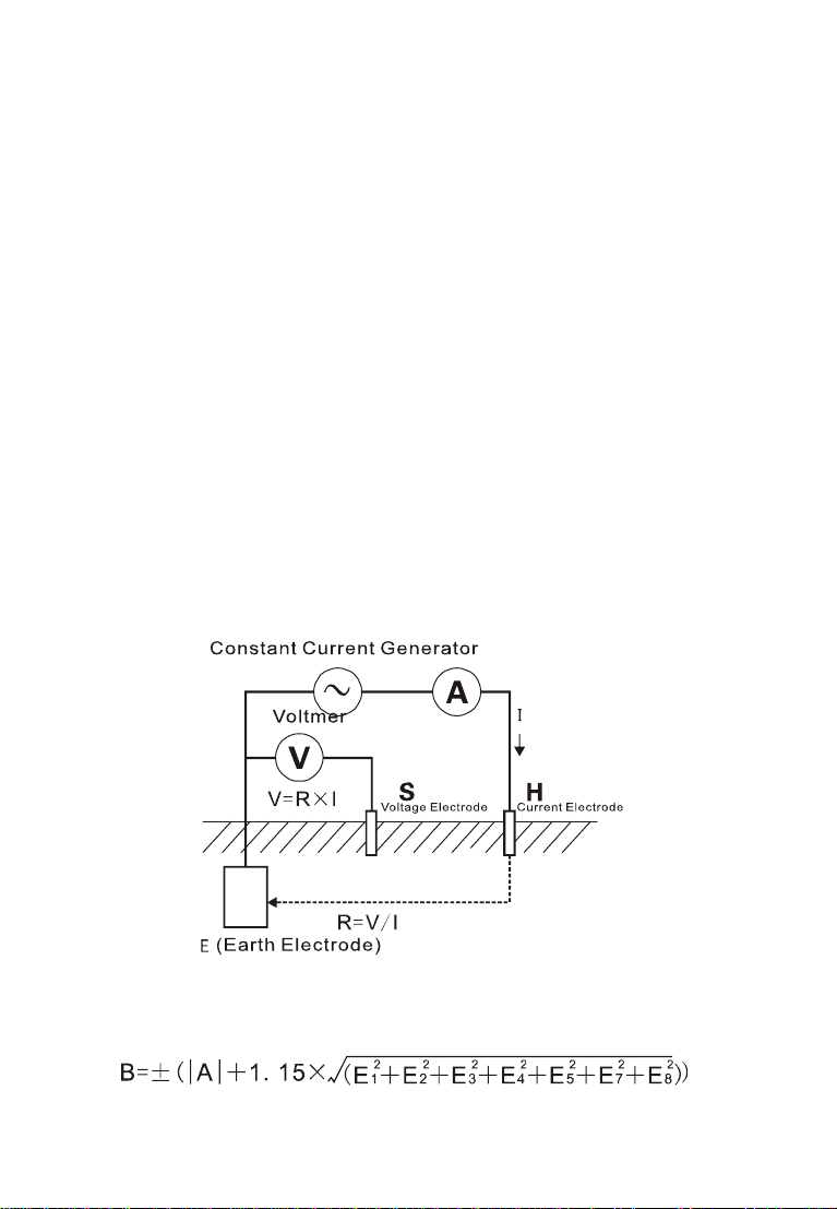
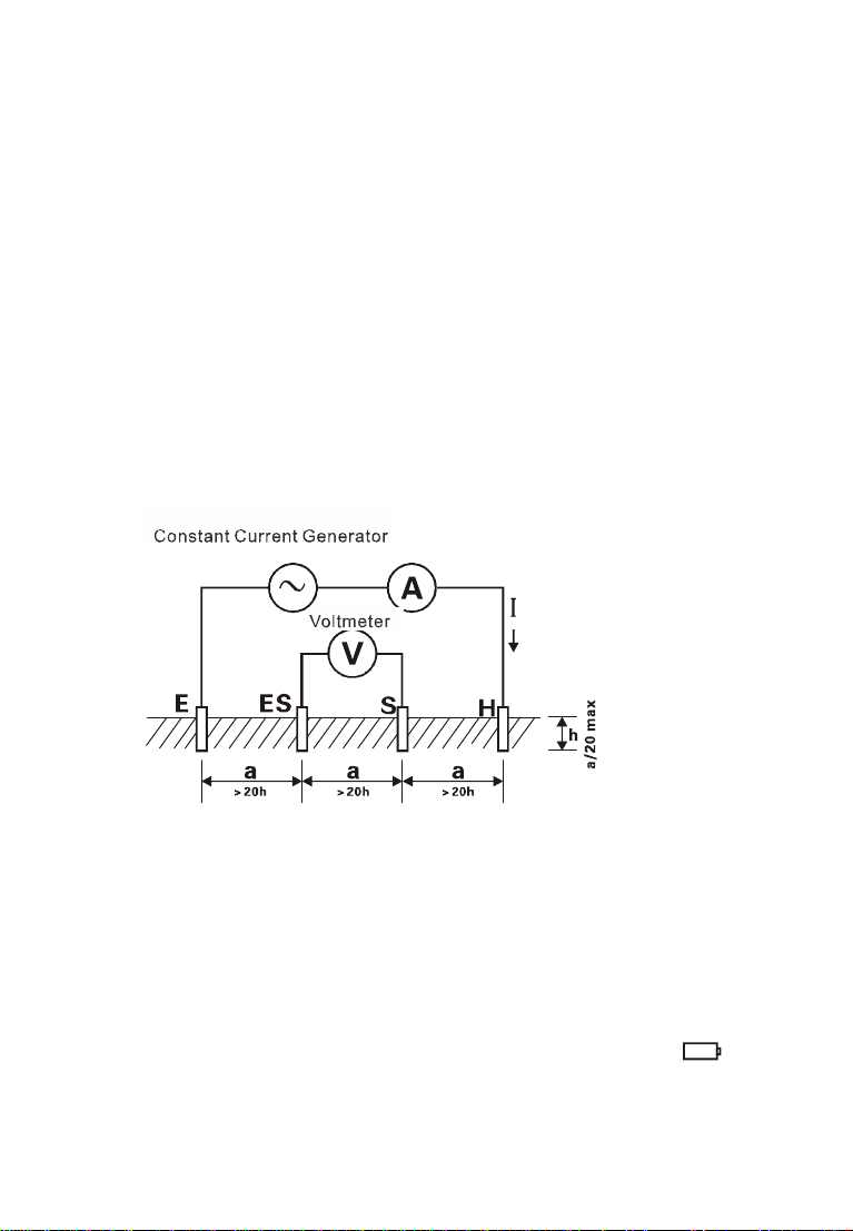
Ground Resistance Soil ResistivityTesteralsoknown
as Four-WireGroundTester,PrecisionGround Resistance
Tester,etc., isacommonlyused meterformeasuring grounding
resistance.It adoptsalarge LCDgray-whitescreen backlight
displayandmicroprocessortechnologytomeettherequirements
oftwo-wire,three-wireand four-wiretestresistance andsoil
resistivitytest. Suitablefortelecommunications,electricity,

4
meteorology,computerrooms,oil fields,powerdistribution
lines,iron towertransmission lines,gas stations,factory
grounding networks,lightning rodsand soon.Instrument
testing isprecise, fast, simple, stableand reliable.
The Ground Resistance Soil ResistivityTester is
controlledbythe microprocessorand canautomaticallydetectthe
connectionstatusofeachinterfaceand theinterferencevoltage
and interference frequencyofthe ground network,and has the
functionoftesting theauxiliarygroundingresistancevalue.Atthe
sametimestore500 setsofdata, resistancemeasurement
range:0.01Ω~30.00kΩ,grounding voltagerange:0.01 ~
600.0V
III.Measuring Rangeand Accuracy
Remark:1. Referenceconditions:Accuracywhen RhRs<100Ω.
Operatingconditions:Rhmax=3kΩ+100R<50kΩ;Rsmax=
3kΩ+100R<50kΩ
Category MeasurementRange
IntrinsicError
Resolution
Earth
Resistance
(R)
0.00Ω-30.00Ω±2%rdg±5dgt 0.01Ω
30.0Ω-300.0Ω±2%rdg±3dgt 0.1Ω
300Ω-3000Ω±2%rdg±3dgt 1Ω
3.00kΩ-30.00kΩ±4%rdg±3dgt 10Ω
Soil Resistivity
()
0.00Ωm-99.99Ωm
ρ=2πaR
(remark2)
0.01Ωm
100.0Ωm-999.9Ωm 0.1Ωm
1000Ωm-9999Ωm 1Ωm
10.00kΩm-99.99kΩm
10Ωm
100.0kΩm-999.9kΩm
100Ωm
1000kΩm-9999kΩm 1kΩm
EarthVoltage AC 0.00-600V ±2%rdg±3dgt 0.01V

5
2.Depending onthemeasurementaccuracyofR, π=3.14,a: 1m
~100m;
IV.TechnicalSpecifications
Function Two,three,four-wiremeasuregrounding resistance,
soilresistivity; Groundvoltage,AC voltage
Ambient
temperature
and humidity 23℃±5℃,below75%rh
PowerSupply DC 9V6-section LR14 DryBatteryStandbyformore
than 100 hours
Interference
current<2A(shouldbeavoided)
MeasureR
electrode
spacing a>5d
Measured
electrode
spacing a>20h
AuxiliaryEarth
Resistance ReferenceConditions<100Ω,OperatingConditions
<5kΩ
Range Groundingresistance:0.00Ωto30.00kΩ
Soil resistivity: 0.00Ωm~9999kΩm
Ground voltage:0.00V to600.0V
Measurement
Method Precision4-wire,3-wiremeasurement,simple 2-wire
groundingresistance
Measuring
Methods
Groundingresistance: ratedcurrentchange method
Soil resistivity: four-pole method
Ground voltage:averagerectification (S-FR interface)
Test Frequency
128Hz
Short
-
circuit
Test Current AC >20mA(sine wave)
Open Circuit
Test Voltage AC 28V max
Electrode
SpacingRange
can be set from1mto100m
Change Gear Groundingresistance:fullyautomaticshiftingfrom
0.00Ωto30.00kΩ
Soil resistivity:0.00 Ωm~9000k Ωmautomatic

6
shifting
Backlight
Grayscreenbacklight, suitablefor dimplaces
DisplayMode 4-digitalsuper-largeLCD display,bluescreen
backlight
Measuring
Indicator During measurement, LED flash
LCD
Frame
Dimension 111mm×65mm
LCD display
area 108mm×65mm
Dimension L×W×H: 240mm×188mm×85mm
StandardTest
Wire 4wires:eachforred 20m,black20m,yellow10m,
and green 10m
Simple
Test
Wire 2wires: eachfor yellow1.5mand green 1.5m
Auxiliary
Earthing Rod 4PCS
Measuring Rate
Voltage toground:about 3times/second
Earthresistance,soil resistivity: about7seconds/time
Circuit Voltage belowAC 600V
DataStorage 500 sets, “MEM”icon storage indicator,flashdisplay
“FULL”icon toindicatestorageis full
DataRead Datareadfunction: “MR”icon display
Overflow
Display Exceedingmeasuring range overflowfunction: “
OL
”
icondisplay
AlarmFunction
Alarmwhen themeasured value exceedsthe alarm
setting value
BatteryVoltage
Lowbatteryvoltagesymbol display
Power
Consumption
Standby:About 40mA(backlight off)
Turnon and backlighton:about 43mA
Measurement: about75mA(backlight off)
Weight Tester:1230g (including battery)
TestingWires:1300g
Auxiliaryearthingrod:720g(4PCS)
Working
Temperature&
Humidity -10℃~40℃;below80%rh

7
Storage
temperature&
humidity -20℃~60℃;below70%rh
Overload
Protection Measuring earthgroundresistance:betweeneach
interfacesof H-E、S-FR,AC 280V/3seconds
Insulation
Resistance Over 20MΩ(between circuitandenclosureit is500V)
Withstanding
Voltage AC 3700V/rms (Between circuit and enclosure)
Electromagnetic
Features IEC61326(EMC)
Protection Type
IEC61010-1(CATIII 300V,CATIV 150V,Pollution
Degree 2);
IEC61010-031;
IEC61557-1(grounding resistance);
IEC61557-5(soil resistivity);
JJG366-2004
V.TesterStructure
1. LCD 2. C(H) interface: Currentelectrode
3. P(S) interface: Voltage electrode
4. ES interface:Auxiliaryearthelectrode

8
5. Einterface:Earthelectrode6. Button area
7. Rotaryswitchforselecting function8. Test button
9. Safetyalligatorclip10. Standardtest wires
11. Auxiliaryearthing rods12. Simple testwires
13. Interfaceof testing wires
VI.Measuring Principle
1. Groundvoltage measurement usesaverage rectification.
2.The grounding resistancemeasurementadoptstheratedcurrentchange
pole method,thatis,thealternating currentrated currentIflowing between the
measuring objectEgroundelectrode andthe Hcurrentelectrode,toobtain
the potentialdifferenceVoftheEground electrode andSvoltageelectrode,
and according totheformulaR=V/ ICalculatethe ground resistancevalue R.
Inordertoensurethe accuracy ofthe test, afour-wiremethod wasdesigned
toincreasethe FRauxiliaryground.Duringactualtesting,FRand Ewere
clampedatthesamepointofthegroundingbody.The four-wiretestcan
eliminatethe influenceofthe contactresistance(usuallydirtorrust)onthe
measuredgroundingbody,auxiliarygroundingrod,testclip,and theinput
interfaceoftheinstrumenttothemeasurement, andcaneliminatethe
influenceofthe wireresistanceon the measurement, moreprecision.
3Itsoperatingerror(B) isan errorobtained within therated operating
conditions,andcalculated withthe intrinsic error(A) and theerror(E) due to
variations.

9
A:Intrinsicerror
E2:Variation due topower supplyvoltage
E3:Variation due to temperaturechange
E4:Variation due tointerferencevoltagechange
E5:Variation due tocontact electrode resistance
4.The soilresistivity(ρ)ismeasured using the 4-pole method(Winner
method): the alternating currentIflowsbetween theEground electrode and
the Hcurrentelectrode,andthe potentialdifferenceVbetween the Svoltage
electrodeand theFRauxiliarygroundelectrodeiscalculated.Thepotential
differenceVisdivided bythealternating currentIobtainsthe grounding
resistancevalue R, the electrode spacingdistanceisa(m), andthesoil
resistivityvalue is obtained according tothe formula ρ=2πaR(Ωm), andthe
distancebetween the HS pitchand the S-FR is equal(botha), that is Wenner
method.Foreaseofcalculation,pleasemaketheelectrodespacingamuch
largerthan the buried depthh,generallyshouldmeeta> 20h,see the figure
below.
VII. Operation Methods
1.SwitchOn/Off
Turnthe function keytothecorrespondingtestposition and turniton.
Turnthe function keytothe OFF position toturnoffthe instrument. After
poweron,thereis"APO"displayed inthelowercorner.If itisnotoperated,it
will be automaticallyturnedoffafter15 minutes.
2.BatteryVoltageCheck
Afterswitchon,ifLCD displays lowbatteryvoltage icon““,which
indicatesthat batteryvoltage islow, andpleasereplacethebatteryintime.

10
3.Ground voltagemeasurement
One auxiliarygrounding rodis required forthegroundvoltagetest.
Aslongasthe instrumentisconnected tothegroundthroughthetest
wire andtheauxiliarygroundingrod,theothertest wiresofthe
instrumentinterfacecannotbeconnectedtotheLandNwiresofthe
commercialpower supply.Otherwise,theleakagemayoccur,andthe
circuitbreakermaystartupandbedangerous.
Groundvoltagetest cannotexceed600V.
Groundingvoltage:when thegroundfaultoftheelectricalequipment
occurs,thepotentialdifferencebetween the groundingdevice casing,the
groundingwire,thegrounding bodyandthezeropotentialpoint,the
groundingvoltage isthereferencepointof the ground,thepotential difference
fromthe earth,and the earthiszeropotential point.
Anauxiliarygrounding rodisrequiredfortheground voltage test.Note
the differencefromthe commercialACvoltagetest.Seethefollowing figure:
Afterthemeter,auxiliarygroundingrod,andtestlineareallconnected,after
turningon the power, turnthe function selection keytoU. The LCD showsthe
test result.
4.WireResistance Verification
Inordertoimproveprecisionand stabilityoffield measurementofearth
ground resistance,avoid errordue towireresistancechange due toprolonged
usageoftestingwires;avoiderrordue totesting wirethatisfailedtobefully
inserted intotesterinterfaceorbypoorcontact; avoid errordue tousers
replacingorlengthening testingwiresand etc.,wireresistanceverification is
speciallydesigned,whichismoreaccurateon lowvalue resistance
measurement.
Asshowninthefigurebelow,pressthe functionbuttonRbutton toswitch
tothecorrespondinggroundresistancemeasurementposition,press
button tostart verification.During verification,During the calibration,the
LED indicatorflashes.TheLCD countsdown.Afterthe calibrationis

11
completed,theLCD displaysthe lineresistanceandstoresthevalue.The
checkedlineresistancevalueisautomaticallydeducted fromthisstart-up
groundresistancemeasurement.
Shutdowndoesnotsavethecalibrationline resistance.The nexttimeyou
turnonthepower, you need to verifyagain..
5.Grounding Resistance Precision Measurement
Whentesting the groundingresistance,first confirmthe grounding
voltageofthegroundingwire,thatis,thevoltagesofHandEorSand
FR must beless than20V.Ifthegroundingvoltageismore than5V,the
measuredvalueofthegroundingresistancemaybeinaccurate.Atthis
time, themeasuredgroundingdeviceshouldbepowered off first, sothat
the grounding voltage isreduced andthen the grounding resistancetest
isperformed.
Four-wiretest: Thefour-wiretesteliminatesthe influenceofthecontact
resistance(usuallydirt orrust) on the measuredgroundingbody,auxiliary
groundingbar,testclip,andtheinputinterfaceoftheinstrumenttothe
measurement,eliminating the effectofthewireresistancetothe
measurement. It is betterthanthe three-line test.
See the following figure:Beginning withthe measured object, generally
spaced 5m~20m,respectively,the S, Hauxiliarygrounding rod isburied
deep intotheground in astraightline,the ground testline(black,green,
yellow,red)fromthe instrumentE, FR,S, and Hinterfacesareinitially
connected tothe groundelectrode Eundertest,the auxiliaryvoltage electrode
S, and the auxiliarycurrent electrodeH.
The distancebetween themeasuredgroundingbodyEandthecurrentpole
Hshould be atleast5timestheburied grounddepth(h)ofthe measured
groundingbody,or5timestheburiedgroundelectrode length(d).
Measurethetotalgrounding resistanceof acomplexgroundingsystem. The
distancedis thedistanceof thelargest diagonalof thegrounding system.
During thetest,thetestleadscannotbeintertwined witheachother.
Otherwise,thetest accuracy maybeaffected.

12
Foramulti-pointindependentgrounding systemorageodeticgrounding
system,theusercanchoosealongertestline,andthe electrodespacingis
greaterthan 5timesthe maximumdiagonallengthofthetested network.As
shownbelow:
R=r1∥r2∥r3∥r4∥r5∥r6∥...∥rn(r1...rnareallindependent earthpoints)

13
R——meterreadings,total groundingresistanceoftheentiregrounding
system;
R1...rn-areallindependentgrounding points,andgroundingbodiesarenot
connected together under the ground;
RH—ground resistanceofauxiliarycurrentpoleH;
RS - groundresistanceof auxiliaryvoltage pole S;
n-thenumberofindependentgroundingpoints,themorepoints,thesmaller
the R value.
6.Three-wireTestGrounding Resistance
Three-wiretest:Asshowninthe figurebelow,short-circuit the FR
and Einterfacesoftheinstrument,thatis,the three-wiretest,andthe
instrumentoperation isthe sameasthe four-wire test.Thethree-wiretest
can noteliminate the influence ofthe wire resistance on the measurement,
norcan it eliminatethe influence ofthe change ofthe contactresistance
between the instrumentand the testwireand between thetestwireand
the auxiliarygrounding rod,and the oxide layeron the surface ofthe
ground bodyto be measured needsto be removed.
7.Two-wireeasyTestGrounding Resistance

14
Second-linetest: Thismethod isasimple measurementmethod thatdoes
notusetheauxiliarygroundingrod.Itusesthe existinggroundingelectrode
withthe smallestvalueofthegroundingresistanceasthe auxiliarygrounding
electrode,and usestwosimpletestlinestoconnectthe HS interfaceand the
E-FRinterface.). The auxiliaryground rodsHandSmaybe replaced with
metallicgroundpipessuchasmetalwaterpipesand firehydrants,common
grounding ofcommercialpowersystems,orlightningprotectiongroundsof
buildings,etc.,andthe oxide layerofthe connection pointsofthe selected
metalauxiliarygrounding bodyshould beremoved during measurement. Floor.
Wiringasshownbelow, the instrumentoperationwiththe four-wiretest.
When usingthecommercialpowersystemgroundingasanauxiliary
grounding polemeasurement,itmustbeconfirmedthatitisthe
groundingpoleofacommercialpower system. Otherwise,thecircuit
breakermay start upandbeindanger.
Useasimple two-wire methodtomeasurethe groundingresistance,and
trytoselectthegrounding bodywithasmallrevalueasthe auxiliary
grounding electrode sothatthe meter readingiscloser tothetruevalue.
Whenmeasuring,pleaseselectthemetalwater pipe and metalfire
hydrant astheauxiliarygrounding electrode.
Two-wireeasyTestGroundingResistanceitsreadingon Testeristhe

15
total value ofearthgroundresistancevalue ofmeasuredearthing objectand
that ofcommercial earthingobject,namely:
RE=RX re
Inwhich: RE isthe Tester reading value;
RX is the earthground resistancevalue of measured earthing
object;
re istheearthground resistancevalue ofcommon earthing
object likecommercial usepower system.
Then,the earthgroundresistancevalueofmeasured earthing objectis:
RX=RE-re
8.Soil ResistivityTest
The soil resistivity isan importantfactorthatdeterminesthe
grounding resistance ofthe grounding body.Differenttypesofsoil,of
course, havedifferentsoil resistivities,thatis,even the samekind ofsoil,
becauseofdifferenttemperatureand moisturecontent,thesoil resistivity
will alsochange significantly.Therefore, inordertohave acorrectbasis
inthe design ofthe grounding device, sothatthe designed grounding
device can moremeetthe actualneedsofthe work,thesoil resistivity
mustbe measured.
The soil resistivitywasmeasured bythe four-polemethod (Winner
method).
The soil resistivity iscalculated according tothe formula =2πaR
(Ωm), and the unit is Ωm, and:
a -electrode spacing
R——Soil resistance between S-FRelectrodes
Four-polemethod (Winnermethod): Connectthe testwireasshown
below.Payattention tothe space between theauxiliarygrounding rods
and thedepthofburial.H,S,FR,and Eauxiliaryground rodsareburied
inthe ground andburied deep intothe earth. The groundtestlines(red,
yellow, green, and black)are connected fromthe H, S, FR, and Eports of
the meterto the H, S, FR, and Eauxiliaryground bars undertest.

16
Auxiliarygrounding rod spacing setting:Afterconnecting the testline,
press the function button ρtoenterthe soil resistivitytestmode, press
and holdtheSETbutton (morethan 3seconds)toenterthe spacing
setting ofthe auxiliarygrounding rod, press the “”keyshortlyto
movethe cursor,press""or""keytochangethe currentnumber
size (avalue range:1m~100m),and thenpressthe SETkey(morethan
3seconds) tosavethe setavalue, and returntothe soilresistivitytest
mode
Afterthe value ofaisset,inthe soil resistivitytestmode, press the
“TFRT”keytostart the testand countdowntodisplaythe test
progress.Afterthe testiscompleted, astablesoil resistivityvalue is
displayed.

17
9.BacklightControl
Afterstartup,press ““buttontoturnon oroffbacklight. The backlight
functionissuitable todarkspot. Itwill defaultbacklightturn-offforeach
startup.
10.Alarm Settings
Afterpoweron,short press “”toturnonandoffthe alarmfunction.
Short press "SET"keytosetthe resistancealarmvalue,press ""keyto
movethe cursor,press ""or""keytochange thecurrentsize,andthen
press"SET"keytosaveandexit. When the measuredvalueisgreaterthan
the alarmcriticalsetting value and thealarmfunctionisturned on,the meter
displaysthe“”symbol and issuesa“beep-beep-beep--”alarmsound.The
maximumvalue ofthegroundvoltagealarmsettingis100V,themaximum
value oftheground resistancealarmsettingis 3000Ω,andthe maximum
value ofthe soilresistivityalarmsettingis9999Ωm.Asshownbelow:
11.DataLock/Storage
Startup oraftermeasurement, press buttontolock current
displayed data,showing icon andautomaticallystorewithserial
numbers.If storageisfull,the Testerwill display icon.toremovelock.
Asshownin figurebelow:the lock measurementdatais1032Ω,press
buttonsaveasthe 3thgroup of data .
12.DataReview/Deletion
Startup oraftermeasurement,press button foralongertime(over
3seconds)toenterdatareading,theinterfacecorresponding tothestored
datainterfaceandthe storeddatagroup numberflashalternately.Press

18
orbuttontoselectreadingdatagroupnumberbystep value 1,press
orbutton constantlytoselectreading datagroup numberbystep value 5,
and then pressbuttontoexit fromreading.
Inthe figurebelow,thenumber3isthecurrentgroupnumber,and6is
the total groupnumber, LCD will display“NULL”, see theabovefigure.
Under datareading status, press SET buttontoenter datadeletion, press
ortoselect “no”or “YES”,selecting “no”and thenpressing SET button
fornotdeleting and returndatareading status,selecting “YES”and then
pressing SET button fordeleting stored dataanditwill showasaboveright
figureafter deletion.
IX.BatteryReplacement
Theinstrumentuses9V6-section LR14 drycell battery,when the
batterypowerisreduced, thepowerindicatorbarisreduced. Whenthe
voltage dropsto5V,thebatterysymbol “”isdisplayed.Please
replace the batteryintime. Lowvoltage affectsthemeasurement
accuracy.
X.Accessories
Tester 1PC
Tester Box 1PC
AuxiliaryEarthingRod 4PCS
TestingWire 4PCS
Simpletesting wire 2PCS
1.5V battery 6PCS
Manual , QualificationCertificate 1 SET

19
Table of contents
Other FUZRR Test Equipment manuals