it should be handled by a qualified organization.
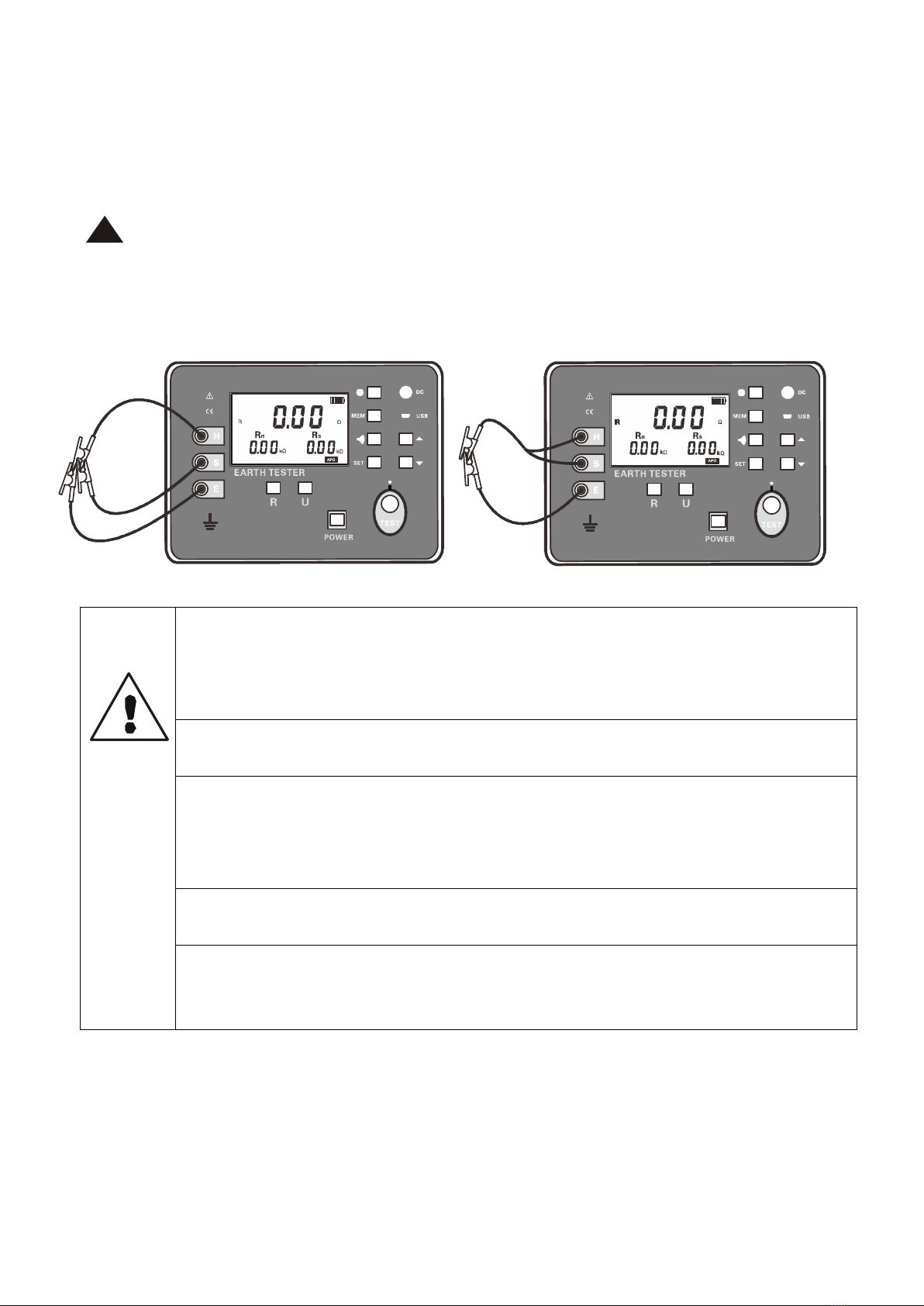
The " " safety warning sign in the instrument and manual must be operated
strictly in accordance with the contents of this manual.
II.Introduction
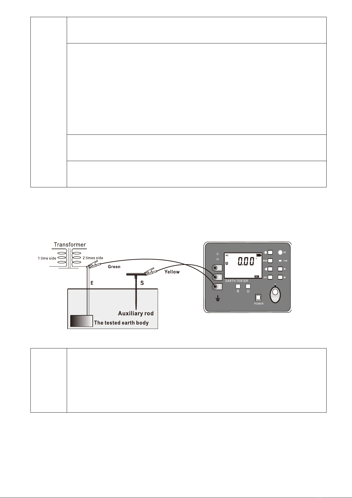
Digital grounding resistance tester, also known as the three-wire
grounding resistance tester, grounding resistance meter, etc., is a commonly
used meter for measuring grounding resistance. It adopts a large LCD
gray-white screen backlight display and microprocessor technology to meet
the requirements of two-wire and three-wire test resistance. Suitable for
telecommunications, electricity, meteorology, computer rooms, oil fields,
power distribution lines, iron tower transmission lines, gas stations,
factory grounding networks, lightning rods and so on. Instrument testing is
precise, fast, simple, stable and reliable.
The digital grounding resistance tester is controlled by the
microprocessor and can automatically detect the connection status of each
interface and the interference voltage and interference frequency of the
ground network, and has the function of testing the auxiliary grounding
resistance value. At the same time store 500 sets of data, resistance
measurement range: 0.01Ω ~ 3000Ω, grounding voltage range: 0.01 ~ 100.0V.
Online monitoring data through monitoring software, USB data uploaded to PC
and unique features such as intelligent alarm alert
The digital grounding resistance tester consists of host, monitoring
software, test line, USB cable, and grounding rod. It has the functions of
reading, checking, saving, reporting and printing of historical data.
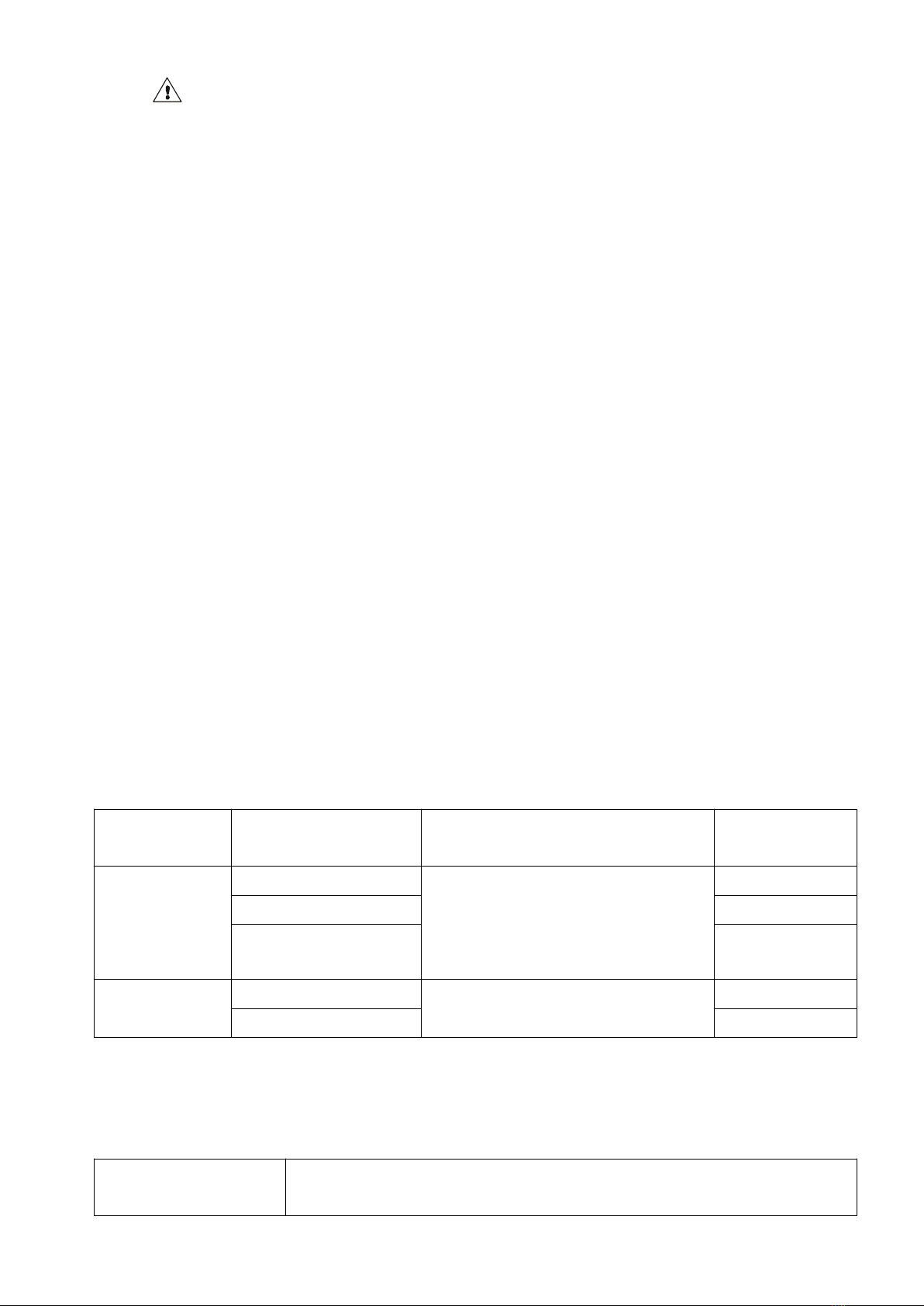
III. Rang and Accuracy
±1.5%rdg±5dgt
(Auxiliary ground
resistance 100Ω ± 5%,
voltage to ground <10V)
(Remark:23℃±5℃,below 75%rh)
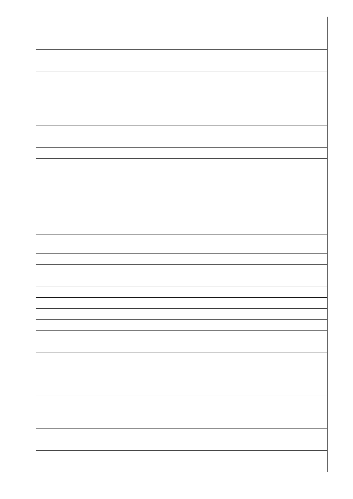
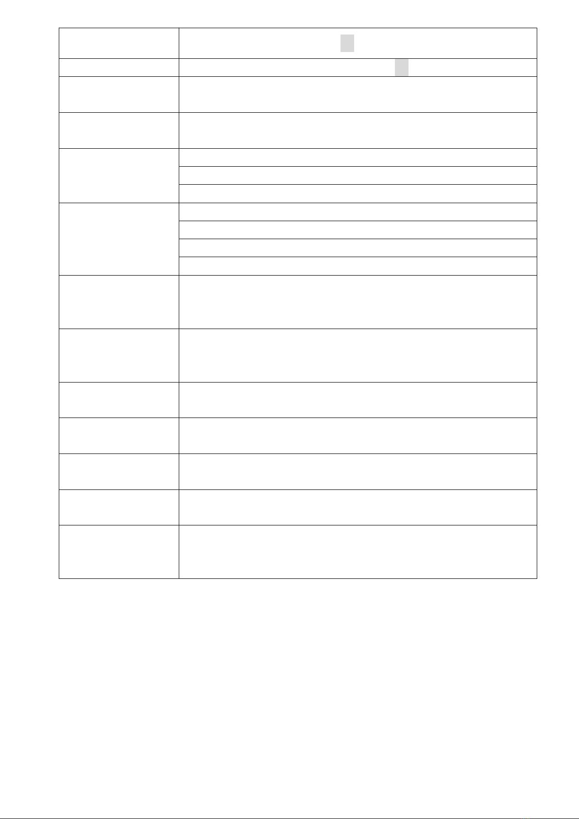
IV.Technical Specifications
Grounding
Resistance Range
0.01Ω~3000Ω Accuracy ±1.5%rdg±5dgt