Fytech FYMIG307 User manual

Instruction Manual
Our equipment is approved by the following car manufacturers
FYMIG307

CONTENTS
1. Safety Precautions Symbols
2. Symbols and Descriptions
3. Installation
3.1 Specifications
3.2 Duty Cycle and Overheating
3.3 Machine Installation
3.4 Selecting a Location
3.5 Installing Gas Supply
3.6 Connecting Input Power
3.7 Threading Welding Wire
3.8 Changing Drive Roll
3.9 Typical MIG Process Connection
3.10 Welding Gun
3.11
4. Operation
4.1 Controls
4.2 Holding and Positioning Welding Gun
4.3 Conditions that Affect Weld Bead Shape
4.4 Gun Movement during Welding
4.5 Poor Weld Bead Characteristics
4.6 Good Weld Bead Characteristics
5. Troubleshooting
5.1 Excessive Spatter
5.2 Porosity
5.3 Excess Penetration
5.4 Lack of Penetration
5.5 Incomplete Fusion
5.6 Burn through
5.7 Waviness of Bead
5.8 Distortion
5.9 Other Troubleshooting
Installation of Aluminum Welding Gun
1
2
3
4
5
6
7
8
9
10
11
12
14
15
16
17
18
19
20
21
22
23
24
25
26
27
28
13

▲
▲
◆
◆
◆
◆
◆
◆
◆
◆
◆
◆
◆
◆
◆
◆
◆
Preface
Please read this instruction manual carefully before using and the equipment and refer to it as
needed to ensure the continued safe operation of the equipment.
This instruction manual should be read completely before attempting to use or service the equipment.
Failure to follow the instructions in this manual could result in property damage, severe personal injury, or
death.
The followingwarningsand importantnotices are used in the instructionmanual:
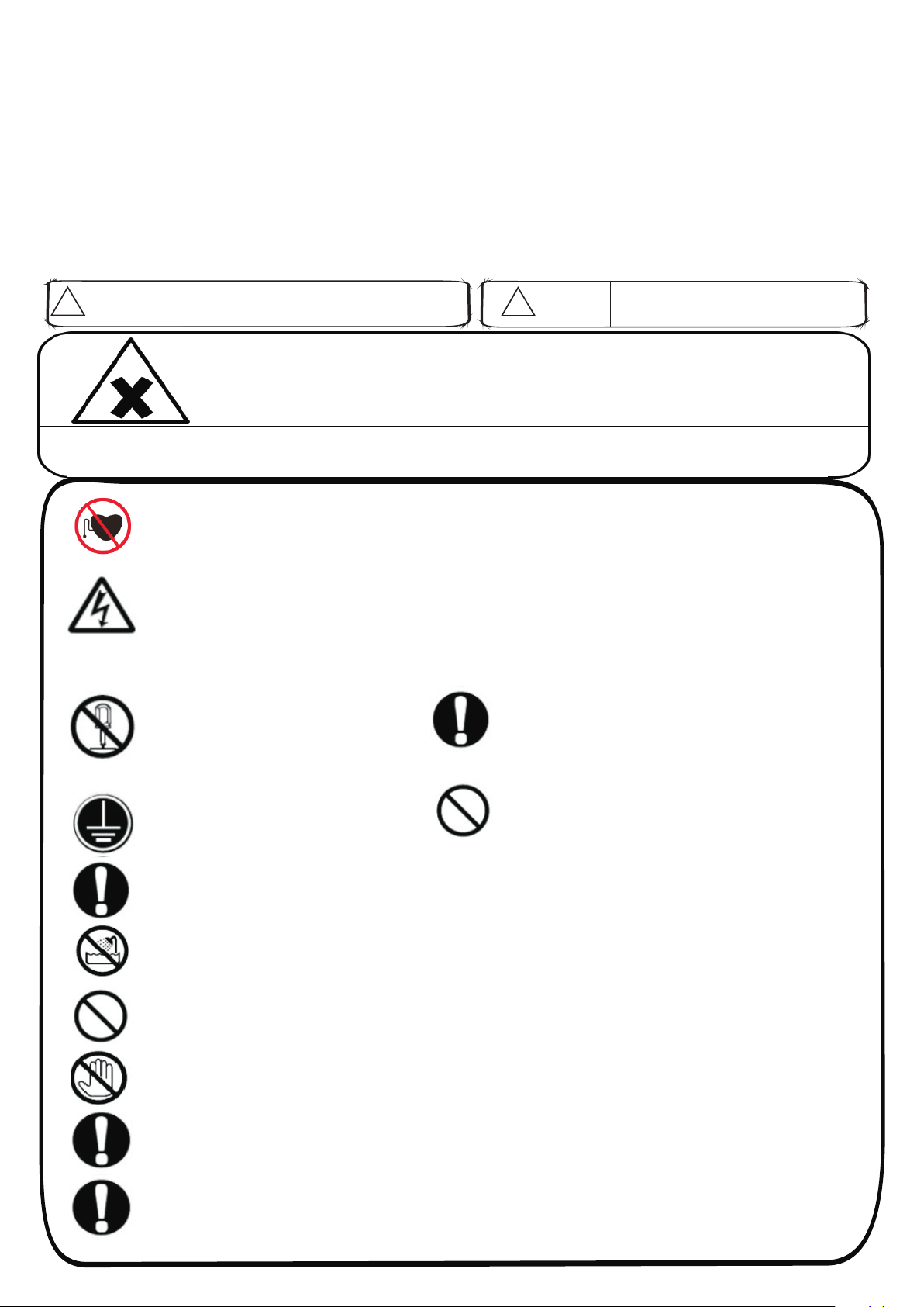
!WARNING
Improper use of this equipment can cause
personal injury or property property damage
操作错误时。有可能会造成人体死亡或重伤的危险
DANGER
Improper use of this equipment can cause serious or fatal injury
.
Magnetic fields can affect pacemakers. Pacemaker wearers keep away from the equipment.
Wearers should consult their doctor before going near equipment operations.
Do not touch any live electrical parts. Wear dry, hole-free insulating gloves and body
protection. The input power circuit and machine internal circuit are live with high voltage
when power is on. Touching live electrical parts can cause fatal shocks or severe burns. High
voltage exists in the power supply socket. Never touch the conductor terminals with bare
hand.
Input power installation must meet national standard. All electrical connections must be
made by a qualified electrician. Insulated gloves and shoes must be worn when connecting
input power or maintaining equipment.
Never disassemble, repair, alter or
rebuild the equipment without approval
from the manufacturer. There is a risk
for electrical shock and fire.
Electric shock can kill. Properly ground
this equipment according to its user
manual and national standard.
Make sure the supply cable is up to national standard or
local code.Use only the right gauge of electrical
wire/cable.There is a risk of fire or electrical shock if
overload building wiring-be sure power supply system is
properly sized,rated and protected to handle this unit.
Replace power cord/wire/cable immediately-bare wiring can kill.
Do not step on, twist or pull the power cord..
Frequently inspect input power cord and regularly clean the unit to
remove dust and dirt.Any worn or damaged power cord or internal
components in heavy dust may cause electrical shock, short
circuit or fire.
In the event of abnormal, operation must be immediately stopped. If smoke, smell or abnormal noise is produced by the
unit, disconnect the power cord immediately and contact your local dealer. Do not use it until the problem is fixed.
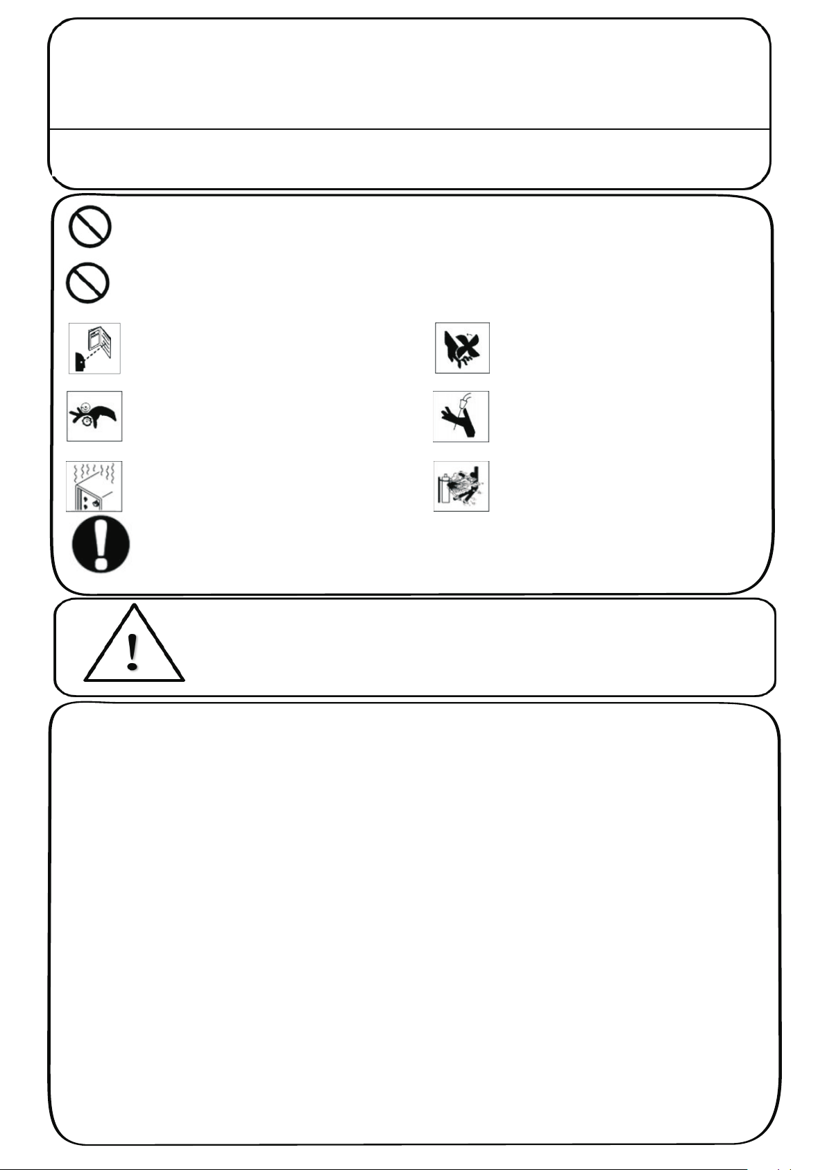
Do not operate or place the device near water or in wet locations. Risk for electrical shock or damage to the device.
Do not operate the equipment in potential hazardous areas : chemicals, oil, gas and mining, or the worksites
where power supply system is in poor condition.
Use only well-maintained device. Inspect and maintain the device for safety every 12 months, including
cleaning and removing dust. Repair or replace damaged parts/cables at once.
Follow the installation and operation instruction to ensure user safety and proper equipment
performance. It is the responsibility of the owner to ensure that the equipment has been installed and
operated as specified in the instructions provided. The manufacturer takes no responsibility for any loss
or damage suffered as a result of using the equipment incorrectly or improperly.
XImproper use of this equipment
can cause serious or fatal injury
◆
◆
◆Hot parts can cause severe burns.Do not touch workpieces or metallic parts of torch with bare hands during or after
welding.Allow cooling period and use a proper tools or wear welding gloves to handle hot parts to prevent burns.

◆
△
!WARNING
Improper use of this equipment can cause personal injury or property property damage
Follow the installation and operation instruction to ensure user safety and proper equipment
performance. It is the responsibility of the owner to ensure that the equipment has been installed and
operated as specified in the instructions provided. The manufacturer takes no responsibility for any
loss or damage suffered as a result of using the equipment incorrectly or improperly.
NOTE
The equipment must be used by qualified personnel familiar with electronic equipment.
Do not place the equipment on unstable or uneven ground. The equipment might fall causing
injuries and damage to the equipment.
During operation process, the equipment should keep a distance about 10cm from the wall to keep air way clear.
Avoid using the equipment in the environments with high humidity (above 90% ), high temperature ( above
40℃),low temperature(below5℃),high frequency source nearby, chemical and drug, water vapor for
condensation, dust or vibration.
Make sure the facility supply voltage and frequency are the same as shown on name plate. The supply
cable must be properly sized and rated.
The connection between the main power supply and the equipment should be as short as possible.
Use a dry cloth to clean the dirt on the equipment.
Do not forget to take back all repair tools/objects inside the equipment after repair/ maintenance, such as
screws, bolts or nuts. The left out metallic objects inside the equipment can cause damage to the
equipment.
Follow the instructions of this user manual to operate the equipment.
We have made installation and operation quick and easy. Please operate the buttons and switches gently with
your hands, only one button each time. The sensitive control circuit will be damaged if pressing the
buttons with a hard and sharp thing such as screw driver and, pen.
Turn off all equipment when not in use.
Follow the installation and operation instruction to ensure user safety and proper equipment
performance. It is the responsibility of the owner to ensure that the equipment has been installed and
operated as specified in the instructions provided. The manufacturer takes no responsibility for any
loss or damage suffered as a result of using the equipment incorrectly or improperly.
◆
◆
◆
◆
◆
◆
◆
◆
◆
◆
The equipment is designed for welding of metals only. Do not use the
equipment for other purposes. This may cause fire or electrical shock
Never place any materials/objects on top of the equipment to avoid fire and
electrical shock.Do not locate equipment on,over,or near combustibles in worksite.
The flying sparks can cause fires and burns.Do not weld where flying sparks can
strike flammable material.
Read instruction manual before using
equipment. Use only the spare parts
supplied or approved by manufacturer.
Moving wire feed rollers and spools can
cause injury when changing welding wire.
Overuse can cause overheating.Avoid
overuse of the equipment which can cause
components to overheat and equipment to
shorter life.
Keep away from moving parts such as
fans. Moving fans cause injury when
changing welding wire.
Keep your hand away from the opening
of the welding torch when the torch
trigger is pressed. The wire coming out
from torch will cause injury of hands.
Make sure gas bottle and gas regulator are
in good conditions. It may cause
explosion if the gas bottle or regulator is
damaged.

U1
U0
U2
I2
s1
HZ
A
V
Primary Voltage
Hertz
IP
X
~
1
V
I
O
+-
%
Adjust Air/Gas
Pressure
Gas Input
Gas Output Do Not Switch
While Welding
Amperes
Volts
Gas Metal Arc
Welding (GMAW)
Gun
On Percent
Wire Feed Off Increase
Line Connection
Loose Shield Cup
Protective Earth
(Ground)
Degree of Protection
Rated Welding
Current
No / Do Not Do This
Single Phase
Power Rating, Products
of Voltage and Current
Duty Cycle
Direct Current
Wire Feed
Spool Gun
Input
Constant Current
Voltage Input
Temperature
Rated No Load
Voltage (Average)
Conventional Load
Voltage
Page 2
Description:
Our semi-automatic welder is an all-in-one MIG shielding gases welder (GMAW) with high
efficiency that is an ideal substitute for manual arc welding. Most advanced circuit design
and technology are adopted. Excellent performances, supreme reliability, quality welding
requirements can be satisfied. Spot weld, groove weld, and fillet weld are available. Most
commonly used shielding gases are applicable such as Co2, AR, CO2+AR, CO2+O, etc.
Suitable for welding of various metallic materials such as mild steel, low carbon steel, low
alloy steel, stainless steel, steel, iron, copper, aluminum, nicket, etc. Extensively used in the
welding and field operation of oil pipeline, chemical, car fabrication, shipyard, etc.
2. SYMBOLS AND DESCRIPTIONS
Symbols and Definitions

50/60
15
310
15.7-35
50
0.6, 0.8, 0.9, 1.0
65%
F
1060*500*1130
10
AC 380
Three Phase
FYMIG306L
50/60
12
310
15.7-35
50
0.6, 0.8, 0.9, 1.0
65%
F
1060*500*1130
8
AC 380
Three Phase
Page 3
3. INSTALLATION
3.1 Specifications
Model
Input Voltage
(V)
Frequency
(Hz)
Rated Input Current
(A)
Rated Output Current
(A)
Output Voltage
(V)
No-load Voltage
(V)
Welding Wire Diameter
(mm)
Duty Cycle
Insulation Class
Dimensions
(mm)
Rated Input Power
(KW)
FYMIG307

0
15
A
Page 4
3. INSTALLATION
3.2 Duty Cycle and Overheating
1. Overheat protection is installed on the aluminium board of main transformer
and rectifier. The unit products heat while welding.
2. If unit overheats, output stops, and cooling fan runs.
3. Wait fifteen minutes for unit to cool. Reduce amperage or voltage, or duty
cycle before welding.
Weld againOverheating Stop working Wait 15 minutes
for unit to cool
Reduce amperage or
reduce duty cycle

Page 5
3. INSTALLATION
3.3 Machine Installation
1. Open the package and find out the Manual.
2. Check the details of accessories according to packing list that attached to this
manual.
3. Properly install this equipment as following diagram. Inspect the unit for any
damage. If so, contact your local distributor or service agency.
4. The unit should not be located under sunshine. The worksite should be in low
humidity and without dust.
5. Operating Temperature range: -10°C to +40°C.
6. Storage Temperature range: -25°C to +56°C.
7. At least 20cm of space for airflow, 30cm of space for two units located side by
side.
8. Use tent to protect the machine from stormy weather when operate outdoor.
9. Welding produces fumes and gases, breathing these fumes and gases can be
3
hazardous to your health. If inside, less than 300m , Ventilate the area.
10. Properly ground this equipment.
11. The input power cord gradient should not more than 15°.

Page 6
3. INSTALLATION
3.4 Selecting a Location
1. Select a correct location to place the unit.
2. Determine input power cord length according to its actual operation
requirement. Input power cord must have a minimum inside diameter of 6mm2.
3. Do not move or operate unit where it could tip.
4. Use cart or unit handle to move unit. Do not pull the cords to move unit.
5. Moving gas cylinder and main unit to hight sparaely.Use lifting eye to lift unit
only, not running gear, gas cylinders, or any other accessories.
6. Optional order for individual wire feeder is available. The wire fe eder and
welding gun divide from the main unit.It is more convenient to operate.

Page 7
3. INSTALLATION
3.5 Installing Gas Supply
1. Cap
2. Cylinder valve (Remove cap, stand to side of valve, and open valve slightly. Gas
flow blows dust and dirt from vavle. Close vavle.)
3. Cylinder
4. Regulator/Flowmeter (Make sure the surface is vertical while installing.)
5. Flow Adjust (Typical pressure is 0.05-0.15MPa.)
6. Hose
7. Hose Connection (Connect gas hose between regulator/flowmeter and the
unit.)
8. Regulator/Flowmeter heating socket (For low temperature worksite, please
plug the regulator/flowmeter to the socket for heating.
DO NOT use other gases regulater/flowmeter
2
with CO shielding gas.
Rear Panel
7
8
ON
OFF
CO2
1
2
3
4
5
6
ON
OFF
CO2
1
2
3
4
5
6

Page 8
3. INSTALLATION
3.6 Connecting Input Power
2
1. Input power cord (not less than 6mm
copper cord).
2. Over-current protection.
3. Disconnect device line terminals.
4. Ground wire L1/L2 input conductors.
Installation must meet all National and Local
Codes. Only qualified persons
are allowed to make this installation.
Disconnect and lockout/tagout input power
before connecting input conductors from unit.
Select type and size of over-current protection.
Close and secure door on disconnect device.
Remove lockout/tagout device, and place
switch in the "on" position.
2
L1 L2
2
1
4
ON
OFF
CO2
ON
OFF
CO2
Power connection and installation must meet all
National and Local standards(Circuit breaker must
be installed).Only qualified persons are allowed to
make this installation.

2
3
4
Page 9
3. INSTALLATION
3.7 Threading Welding Wire
1. Wire spool spindle
2. Welding wire
3. Pressure adjustment knob
1
2
3
1. Open wire spool spindle; install wire spool; release pressure adjustment knob;
pull and hold wire.
Push wire thru guides into drive roll. Close wire spool spindle tightly to prevent
slipping (Feed wire to check wire spool installation).
2. Set a desired drive roll pressure, close and tighten pressure adjustment knob.
3. Press gun trigger and let go of wire.
4. Remove gun nozzle and contact tip.
5. Press gun trigger until wire comes out of gun. Reinstall contact tip and nozzle.
6. Feed wire to check drive roll pressure, tighten knob enough to prevent slipping.
7. Cut off wire if welding wire extends too far beyond nozzle.

1. Drive roll securing nut
2. Drive roll
3. Pressure adjustment knob
4. Press device
2
1
3
4
Changing Drive roll:
1. Release pressure adjustment knob. Press wire device springs open.
2. Loosen securing nut, Remove drive roll.
3. The drive roll consists of two different sized grooves. Reinstall the desired wire
sized groove close to the motor shaft.
4. Tighten securing nut.
5. Replace press wire device, and set a desired pressure.
6. Make sure drive roll groove lines up with wire guide.
Page 10
3. INSTALLATION
3.8 Changing Drive Roll

ON
OFF
CO2
2
3
4
Regulator/Flowmeter
Wire feeder Hose
Shielding gas
Gun
Work clamp and workpiece
Weld current can damage electronic parts in vehicles. Disconnect both battery
cables before welding on a vehicle. Place work clamp as close to the weld as
possible.
Page 11
3. INSTALLATION
3.9 Typical MIG Process Connection

1. Shield cup C012
2. Contact tip C004
3. Front adaptor C010
4. Gooseneck (15/24AK) C020/C018
5. Trigger
6. Spanner
1234
65
Page 12
3. INSTALLATION
3.10 Welding Gun

Page 13
11、Installation of Aluminum Welding Gun
Tools :Cutter and hex wrench Pull out the guide wire
Install into welding gun Cut off the guide wire from the bottom of 3-5mm
Cut off the extended part 11.3mm of the guide wire. Use cutter and hex wrench Loosen the fastening bolts of the bass tube
Pull out the guide wire Install into welding gun Fastened
Advantages : wire feeding more smooth and stable, and without friction in wire feeding
Loosen the fastening bolts of the bass tube

NO.14
Operation
1.In normal welding, the users only need to set the material, wire diamete and
thickness to start to weld. It is unnecessary to set other data. All other data
have been preset by the manufacturer.
2.If the welding is not as good as expected, please fine-tune the current and
wire speed.
3.Resume to the default setting:
Press the 2 buttons of “Data type selector” and 2 buttons of “Welding material
selector” for 1s at the same time. Switch off power supply and then switch on
the welder again. The welder will resume to the default setting as leaving the
factory.
4.When setting “Standard” welding, the “Pulse” can not be adjusted,
displaying”---“.
5.When setting “2-step” and “4-step”,the “Spot time” can not be adjusted,
displaying ”FFF”.
1
2
3
6
7
8 9
1 0
4
5
Setting welding data instruction:
.
1. Data display screen
2. Data adjustment
3. Data type selector
4. Data indicator
5. A/B indicator
6. Welding material
indicator and selector
7. Pulse/Standard mode
indicator and selector
8. Wire diameter indicator
and selector
9. Welding mode indicator
and selector
10.Alarm
1.The data displayed on the screen is according
to the setting of the Data type selector(For example,
when you set material thickness, the screen will show
the thickness of the material)
2. The Data type selector is for selecting the type of data,
corresponding to A/B indicator.
3. Adjust the data by turning the Data Adjustment when
the A/B indicator and Data Indicator are lighting up at the
same time.
Note:
2
1
4
1. Display Screen
2. Data Adjustment
3.Navigation buttons,Left and Right
4.Navigation buttons,Up and Down
3
1. Display Screen
2. Data Adjustment
3.Navigation buttons,Left and Right
4.Navigation buttons,Up and Down

1. Hold gun and control gun trigger
2. Workpiece
3. Work clamp
4. Electrode extension (stickout)
5. Cradle gun and rest hand on workpiece
1
2
3
4
5
End view of work angle
Side view of gun angle
45°
45°
90° 90° 0°-15°
0°-15°
GROOVE WELDS
FILLET WELDS
Welding wire is energized when gun trigger is pressed. Before lowering helmet and
pressing trigger, be sure wire size is correct to past end of contact tip, and tip of
wire is positioned correctly on seam.
Page 15
4.OPERATION
4.2 Holding and Positioning Welding Gun

Weld bead shape depends on gun angle ,direction of travel, electrode extension
(stickout), travel speed, thickness of base metal, wire feed speed (weld current),
and voltage.
Push
Perpendicular
Short
Short
Slow
Normal
Normal
Normal
Drag
Long
Long
Fast
10°
10°
GUN ANGLES AND WELD BEAD PROFILES
ELECTRODE EXTENSIONS (STICKOUT)
FILLET WELD ELECTRODE EXTENSIONS (STICKOUT)
GUN TRAVEL SPEED
Page 16
4.OPERATION
4.3 Conditions that Affect Weld Bead Shape

1. Stringer Bead
Steady movement along seam
2. Weave Bead
Side to side movement along seam
3. Weave Patterns
Use weave patterns to cover a wide
area in one pass of the electrode
Page 17
4.OPERATION
4.4 Gun Movement during Welding
1
2
3
Table of contents
Other Fytech Welding System manuals

Fytech
Fytech FY-5500/2E User manual

Fytech
Fytech FYMIG200L-2 User manual

Fytech
Fytech FY-13000 User manual

Fytech
Fytech FY-7000 User manual

Fytech
Fytech FYMIG5215X User manual

Fytech
Fytech FYMIG5260 User manual

Fytech
Fytech FY-6000 User manual

Fytech
Fytech FY-92G User manual

Fytech
Fytech FY-9000 User manual

Fytech
Fytech FYMIG300 User manual

Fytech
Fytech FY-9G User manual

Fytech
Fytech FY-6G User manual

Fytech
Fytech FYMIG305 User manual

Fytech
Fytech FY-4280/2E User manual

Fytech
Fytech FY-4DM User manual

Fytech
Fytech FYMIG180 User manual

Fytech
Fytech FY-91G User manual

Fytech
Fytech FYMIG305L User manual

Fytech
Fytech FY-9000A User manual

Fytech
Fytech FYMIG270X User manual