3
10.2016 | G28706 | Designed in Germany
1 Essential information
These instructions are an important delivery component and are intended for the persons who
will install, operate or service the product. These instructions provide information about the
product and using it safely.
Please read the instructions thoroughly and pay particular attention to the advisory
notes concerning safety.
Keep the instructions for later reference.
Reliable functioning and the prevention of risk and damage can only be achieved by
accurate assembly and adjustment according to the instructions.
Gretsch-Unitas GmbH Baubeschläge accepts no liability for damage arising from
inappropriate assembly and installation.
After removing all packaging, check that all parts of the appliance are present and complete.
Plastic bags as well as small parts, such as staples, etc. must not
be left within the reach of children. They represent potential danger
sources.
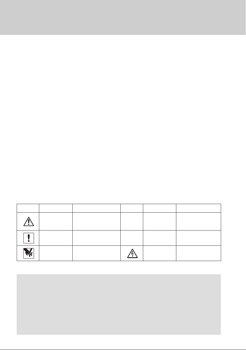
2 General safety advice
It is absolutely essential to observe the following safety instructions.
Additional instructions in other sections of the manual are clearly identified by the symbols listed
above.
Ensure that assembly, installation, and initial commissioning of the equipment are
carried out by trained and qualified persons only.
Observe all regulations and directives applicable at the place of installation; these might
include:
Directives for safety at work
Accident prevention regulations
Regulations concerning electrical and electronic engineering (eg, VDE directives),
DIN/EN standards,
Technical guidelines for workplaces "ASR A1.6 and ASR A1.7 (former guideline for
"Guidelines for Power-operated Windows, Doors and Gates" BGR 232) - Where
required, please request from Gretsch Unitas GmbH Baubeschläge,
Code of practise KB.01 issued by the German association of window and facade
manufacturers (VFF); ask Gretsch-Unitas GmbH Baubeschläge for a copy if necessary.
The product may only be used if it is in full technical working order and for the purpose
intended; it must be handled in a safety-conscious way with due regard to dangers, and
in accordance with the installation and operating instructions.
Attach safety devices such as safety catches or safety stays correctly and ensure that
they are in perfect working order. Check that the opening width of the catching device is
sufficient to match the travel of the chain drive.
Use only original spare parts, original accessories and original fixing materials supplied
by Gretsch-Unitas GmbH Baubeschläge.
Fixing material must be compatible with the structure and supplemented if necessary.
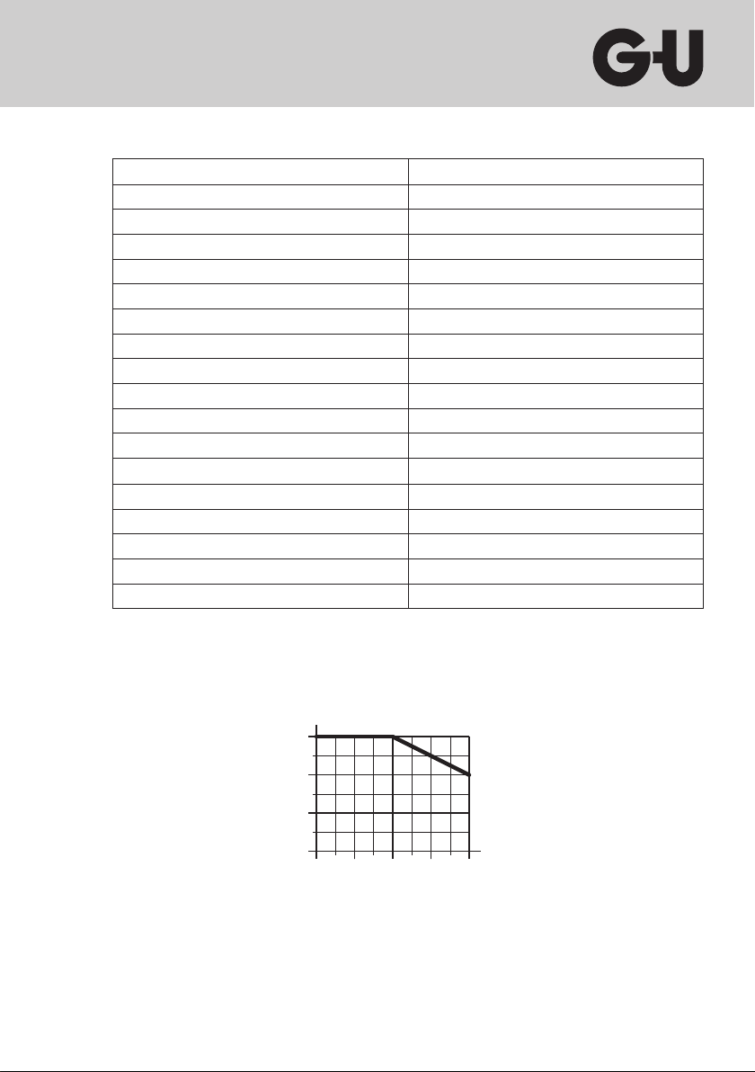
You must always check that your installation complies with applicable regulations.
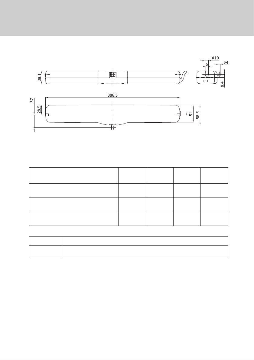
Special attention must be paid to window opening width, permitted installation
dimensions, opening speed, push force, connecting cable cross-section in relation to
cable length and current consumption.
The product is designed for use in dry rooms only. The product must be protected
against dirt and humidity at all times.