manuals.online logo
Brands
  1. Home
  2. •
  3. Brands
  4. •
  5. G4S
  6. •
  7. Card Reader
  8. •
  9. G4S S874 Guide

G4S S874 Guide

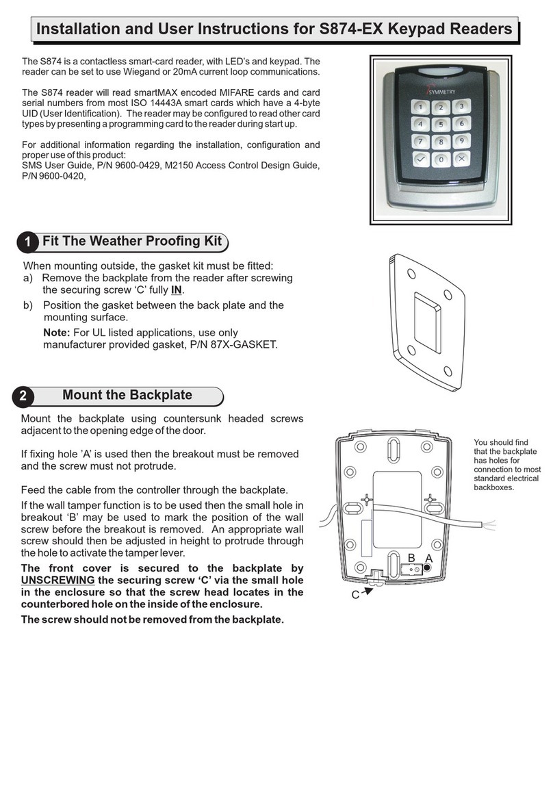
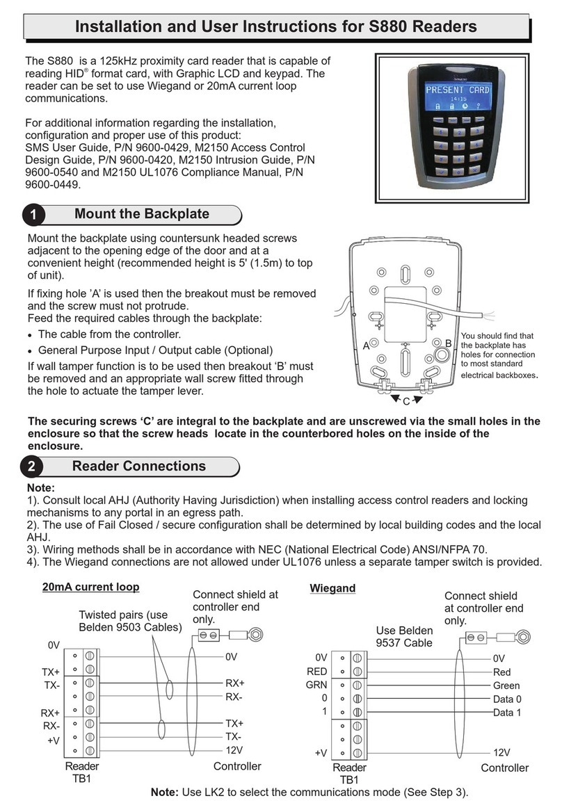
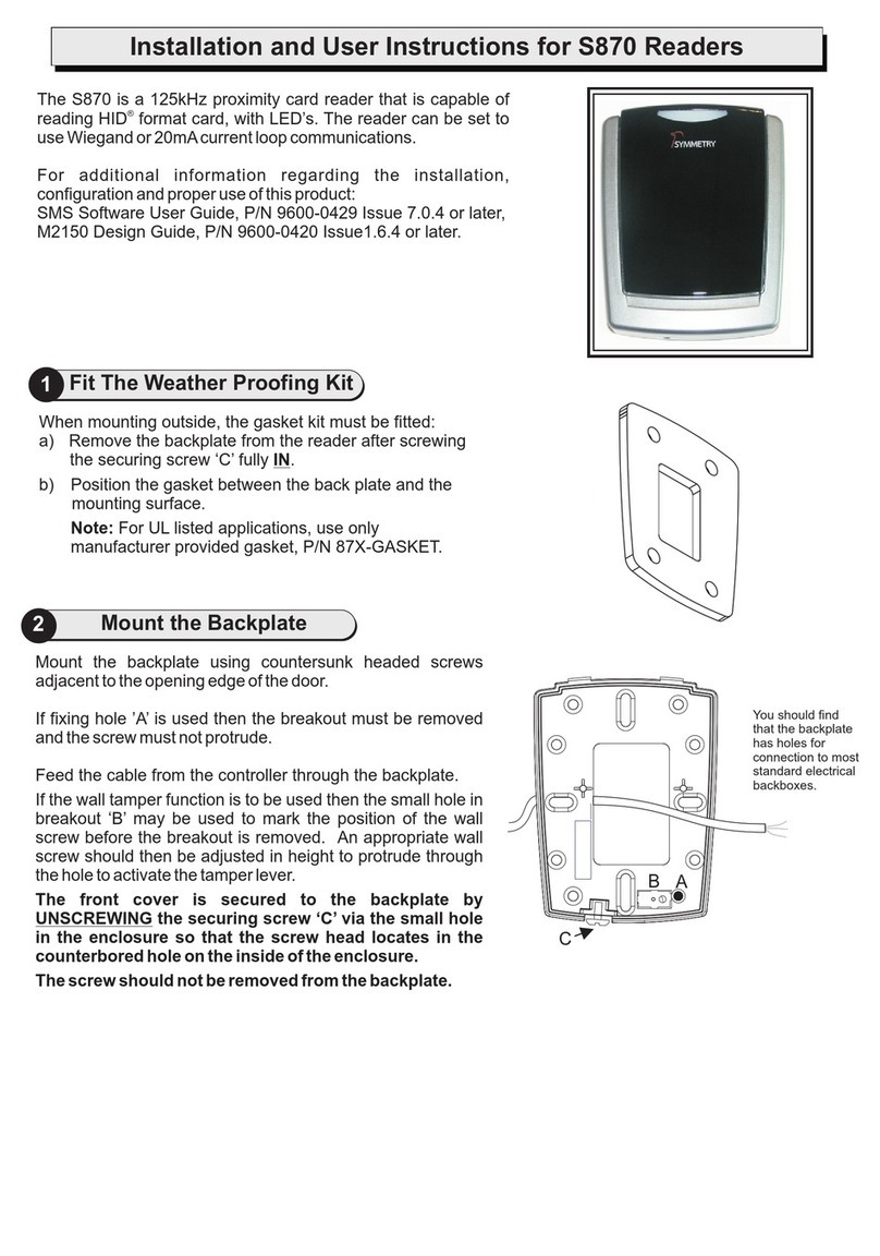
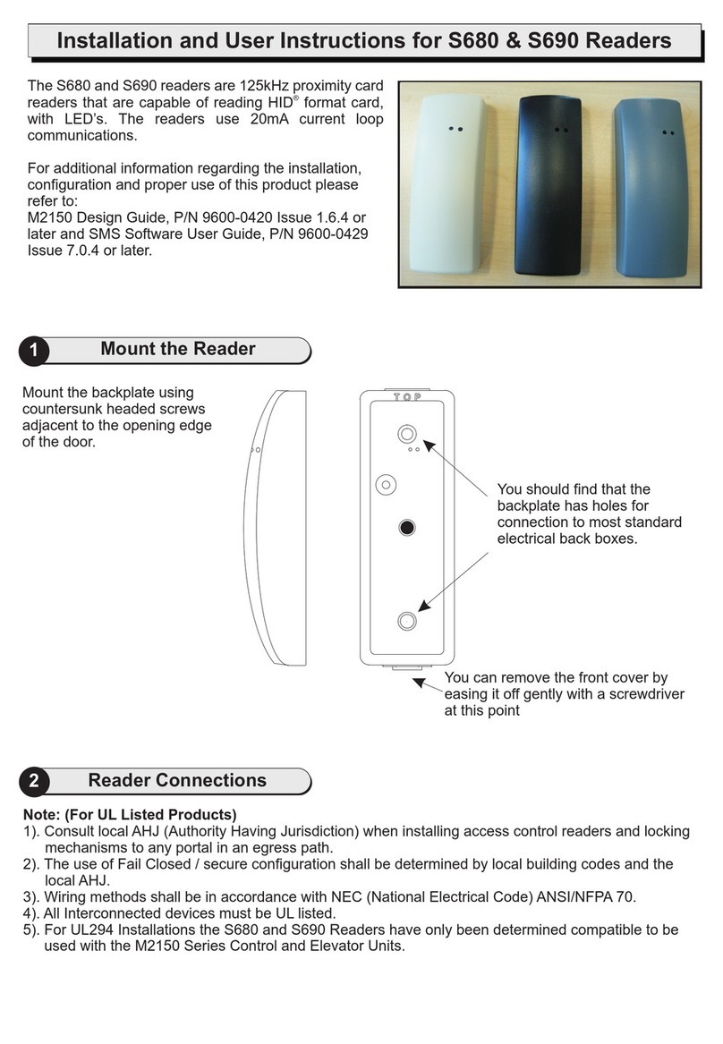
Mount the backplate using countersunk headed screws
adjacent to the opening edge of the door.
If fixing hole ’A’ is used then the breakout must be removed
and the screw must not protrude.
Feed the cable from the controller through the backplate.
If the wall tamper function is to be used then the small hole in
breakout ‘B’ may be used to mark the position of the wall
screw before the breakout is removed. An appropriate wall
screw should then be adjusted in height to protrude through
the hole to activate the tamper lever.
The front cover is secured to the backplate by
UNSCREWING the securing screw ‘C’ via the small hole
in the enclosure so that the screw head locates in the
counterbored hole on the inside of the enclosure.
The screw should not be removed from the backplate.
2Mount the Backplate
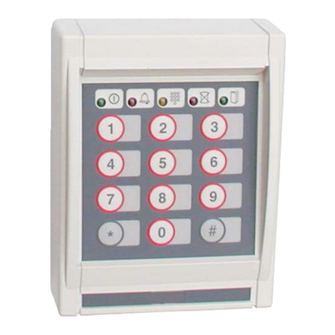
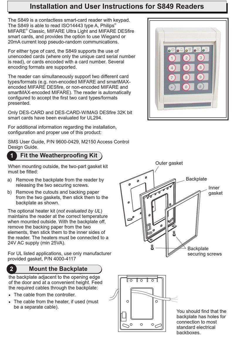
The S874 is a contactless smart-card reader, with LED’s. The reader can
be set to use Wiegand or
The S874 reader will read smartMAX encoded MIFARE cards and card
serial numbers from most ISO 14443A smart cards which have a 4-byte
UID (User Identification). The reader may be configured to read other card
types by presenting a programming card to the reader during start up.
For additional information regarding the installation, configuration and
proper use of this product:
SMS User Guide, P/N 9600-0429, M2150 Access Control Design Guide,
P/N 9600-0420,
20mA current loop communications.
Installation and User Instructions for S874 Readers
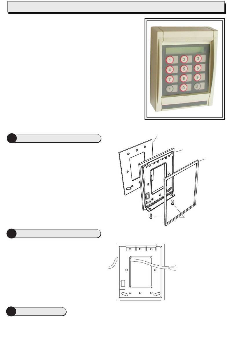
1Fit The Weather Proofing Kit
When mounting outside, the gasket kit must be fitted:
a) Remove the backplate from the reader after screwing
the securing screw ‘C’ fully IN.
b) Position the gasket between the back plate and the
mounting surface.
Note: For UL listed applications, use only
manufacturer provided gasket, P/N 87X-GASKET.
You should find
that the backplate
has holes for
connection to most
standard electrical
backboxes.
C
A
B
4Reader Links
Present the card face-on to the reader until you hear a "bleep". Cards can
be presented in rapid succession; there is no need, for example, to wait for "GREEN LED’s" to disappear before
presenting another.
When faulted, the reader can not accept a card read. Check wiring for faults or replace reader.
The reader is now working correctly.
9600-0595. Installation and User Instructions for S874 Readers, Issue
1.0 31st August 2012. G4S Technology, 2012.
FCC Notice: This device complies with Part 15 of the FCC Rules.
Operation is subject to the following two conditions: (1) This device may
not cause harmful interference, and (2) this device must accept any
interference received, including interference that may cause undesired
operation.
Any unauthorized modification to this device may void the authority of
the user to operate it.All trademarks acknowledged.
©
LED Status Indicator
GREEN –The lock is released and you may open the door.
RED –You do not have access rights to gain entry, or the reader did not read your card properly (in this case,
present it again).
Specifications
Input voltage: 9-14Vdc.
Input current: 120mA @ nom. 12Vdc.
Operating temperature: -13 to 158°F (-25 to 70°C)
Operating humidity: 15 to 90%, non-condensing.
Maximum read range: 4" (100mm).
Approvals: EN302291, EN301489
5Using / Testing the Reader
Set SW1 switch2 (COM) to W for Wiegand communications, or C for 20mA current loop communications. Set
SW1 switch1 (USER F/B - audio feedback) to 1 for sound on, or 0 for sound off.
3Reader Connections
0V
RX+
RX-
TX+
TX-
12V
Controller
0V
TX+
TX-
RX+
RX-
+V
Reader
TB1
20mA current loop
0V
Green
Data 0
Red
Data 1
12V
Controller
0V
GRN
0
+V
Wiegand
RED
1
Reader
TB1
Connect shield at
controller end
only.
Connect shield
at controller end
only.
Note: Use SW1 switch2 to select the communications mode (See Step 5).
Twisted pairs (use Belden
9503) cable or other UL
Listed style 2464 (DUZX)
cable.
Multi conductor (Use
Belden 9537) or other
UL Listed style 2464
(DUZX) cable.
Note: The FERRITE must be fitted!
Slide the ferrite sleeve onto cable before wiring terminal block. Ferrite to be placed 50mm (2") up cable and held in place
with cable ties.
Maximum distance
150m Maximum distance
75m

Other G4S Card Reader manuals

G4S S880 Guide

G4S

G4S S880 Guide

G4S S848 Guide

G4S

G4S S848 Guide

G4S S849 Guide

G4S

G4S S849 Guide

G4S S870 Guide

G4S

G4S S870 Guide

G4S S813 Guide

G4S

G4S S813 Guide

G4S S813 Guide

G4S

G4S S813 Guide

G4S S844 Guide

G4S

G4S S844 Guide

G4S S680 Guide

G4S

G4S S680 Guide

G4S S821 Guide

G4S

G4S S821 Guide

G4S S854 Guide

G4S

G4S S854 Guide

G4S S874-EX Guide

G4S

G4S S874-EX Guide

G4S S830 Guide

G4S

G4S S830 Guide

Popular Card Reader manuals by other brands

Goobay 95674 quick start guide

Goobay

Goobay 95674 quick start guide

ACS ACR3901U-S1 user manual

ACS

ACS ACR3901U-S1 user manual

Fermax MIFARE Installer manual

Fermax

Fermax MIFARE Installer manual

Identiv uTrust 5501F user manual

Identiv

Identiv uTrust 5501F user manual

EOinnovations EOC2100 instruction manual

EOinnovations

EOinnovations EOC2100 instruction manual

StarTech.com 35FCREADBK3 instruction manual

StarTech.com

StarTech.com 35FCREADBK3 instruction manual

Rosslare AY-U910 Installation and user manual

Rosslare

Rosslare AY-U910 Installation and user manual

SCM SwapBox Series Hardware & software installation

SCM

SCM SwapBox Series Hardware & software installation

SimpleTech STI-UMC600 user guide

SimpleTech

SimpleTech STI-UMC600 user guide

Feig Electronic Obid ID RWA02.ABC-A Installation

Feig Electronic

Feig Electronic Obid ID RWA02.ABC-A Installation

E-omnitech OMT601 user manual

E-omnitech

E-omnitech OMT601 user manual

Sony MRW-F3 Read me first

Sony

Sony MRW-F3 Read me first

ENS SK1I01M user manual

ENS

ENS SK1I01M user manual

DoorKing 1815-247 manual

DoorKing

DoorKing 1815-247 manual

Kade KDH-C100U installation manual

Kade

Kade KDH-C100U installation manual

Promate proLink.OT user guide

Promate

Promate proLink.OT user guide

Sony MRW620-U1 operating instructions

Sony

Sony MRW620-U1 operating instructions

IOGear GOFR214 quick start guide

IOGear

IOGear GOFR214 quick start guide

manuals.online logo
manuals.online logoBrands
  • About & Mission
  • Contact us
  • Privacy Policy
  • Terms and Conditions

Copyright 2025 Manuals.Online. All Rights Reserved.