GALTRONICS 62-20-09 User manual

Mounting Instructions Outdoor DAS Antennas
Ø 14.5”x 48” Length - & Ø 14.5”x 24” Length
4
www.ga l tronics.com
Copyright © 2016 – Galtronics Corporation Ltd.
Proprietary Information. All rights reserved. Galtronics reserves the right to modify or amend any antenna or specification without prior notice.
21-234-03 Release Date: 16th September, 2016; Revision: S-4; Patent Pending
Baylin TechnOlogies Company
Model No: 62-20-09 | Mounting instructions outdoor DAS antennas page 1 of 4

PARTS INDENTIFICATION
7/16“ X 11/2” - Bolt (8)
7/16“ - Nut (8)
7/16“ - Plain Washer (16)
7/16“ - Spring Washer (8)
5/16“ - Cup Head Set Screw (2)
5/16“ - Nylon Flange Lock Nut (2)
Support Bracket (1)
Left Bracket (1)
Right Bracket (1)
Stopper Plate(2)
w w w . g a l tronics.co m
Copyright © 2016 – Galtronics Corporation Ltd.
Proprietary Information. All rights reserved. Galtronics reserves the right to modify or amend any antenna or specification without prior notice.
21-234-03 Release Date: 16th September, 2016; Revision: S-4; Patent Pending
7/16“ - Nut (8)
Stopper Plate(2)
7/16“ X 11/2” - Bolt (8)
Left Bracket (1)
Right Bracket (1)
5/16“ - Nylon Flange Lock Nut (2)
5/16“ - Cup Head Set Screw (2)
7/16“ - Plain Washer (16)
7/16“ - Spring Washer (16)
Support Bracket (1)
Baylin TechnOlogies Company
Model No: 62-20-09 | Mounting instructions outdoor DAS antennas page 2 of 4
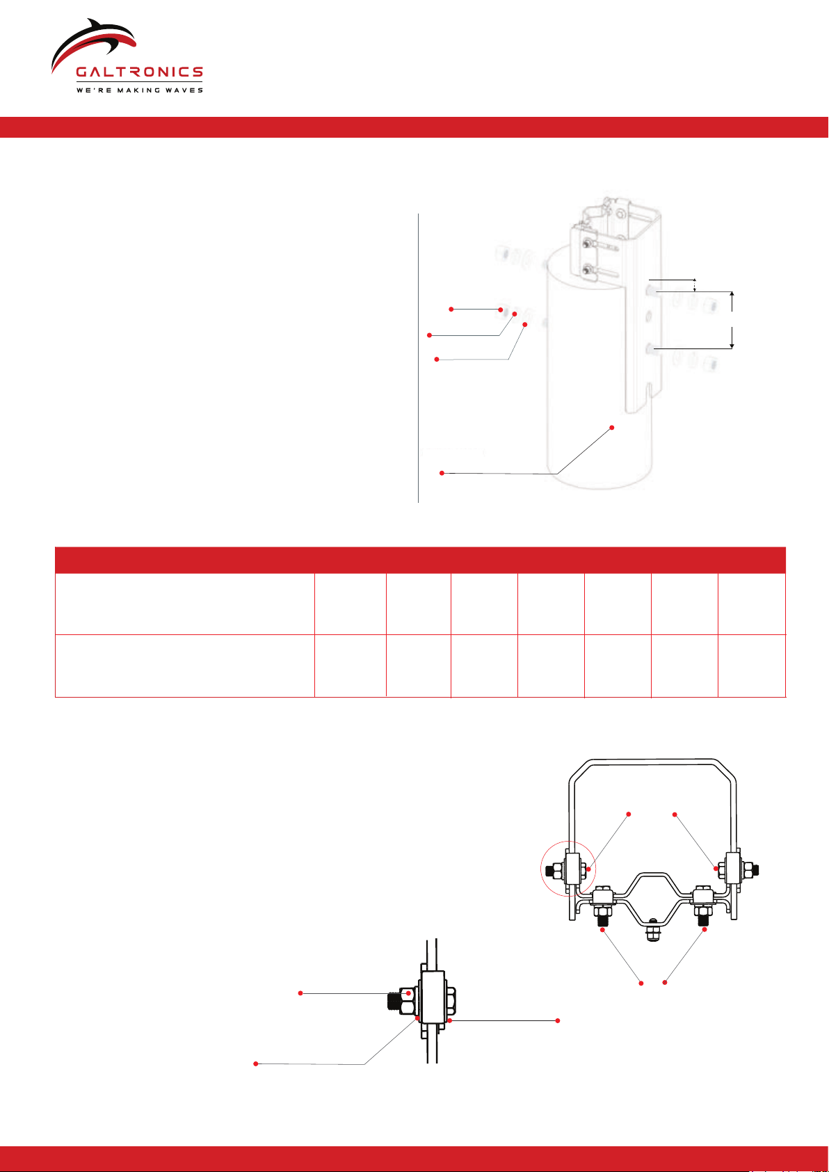
ASSEMBLY INSTRUCTIONS
B. Assemble right bracket stopper plates and left bracket (Clamping brackets)
Use 7/16” fasteners to attach the support bracket,
stopper plates and left brackets without tightening (see details).
For a pole with diameter between 9” - 12”, position the interlock
tabs of the stopper plates towards the support
bracket (see picture detail on the left).
For 6” - 9” pole diameters position, the interlock tabs
away from the support backet.
Tightening hardware to the final position
will be done after placing the antenna
on the pole!
Table 1.1 - Threaded rod length
Pole diameter: 8”
(203mm)
9”
(228mm)
11”
(279mm)
12”
(305mm)
6”
(152mm)
9”
(228mm)
7”
(177mm)
10”
(254mm)
11”
(279mm)
12”
(305mm)
10”
(254mm)
13”
(330mm)
14”
(255mm)
15”
(381mm)
Threaded rod length:
7/16“ X 11/2”
7/16“ X 11/2”
A. Attach support bracket to pole
Drill required hole (Ø 1.1”) through the
wooden pole (see drawing).
Attach the support bracket to the
wooden pole.
Our recommendation:
Use 1” threaded rods and corresponding 1”
plain washer, spring washers and 1″ Nut as shown
in the drawings.
Tighten with a torque of 150Nm (1328 In*Lbs).
Choose threaded rod length according to
Table 1.1.
1″Plain Washer
1″Sping Washer
1″Nut
7/16“ Nut
7/16“ Plain and
Spring Washer
7/16“ Plain Washer
w w w . g a l tronics.co m
Copyright © 2016 – Galtronics Corporation Ltd.
Proprietary Information. All rights reserved. Galtronics reserves the right to modify or amend any antenna or specification without prior notice.
21-234-03 Release Date:16th September, 2016; Revision: S-4; Patent Pending
Baylin TechnOlogies Company
Model No: 62-20-09 | Mounting instructions outdoor DAS antennas page 3 of 4
1.57” (40mm)
6.9” (175mm)
Wooden Pole
(Ø6” to Ø12”)

ASSEMBLYINSTRUCTIONS
C. Antenna Mounting
D. Cup Head Screw Installation
Place the antenna rod on top of the pole and adjust the position
of the right bracket to the center of the pole. Tighten all bolts.
Install 5/16” cup head set screw and
tighten to the appropriate torque. Lock
the antenna rod using the nylon flange
locking hex nut. Tighten hex nut to 15Nm
(132In*Lbs).
E. Check Torque
After adjustment all loosened bolts
must be tightened with a torque of:
5/16˝- 15Nm (132In*Lbs)
7/16˝- 40Nm (354In*Lbs)
1˝- 150Nm (1328In*Lbs)
DO NOT REUSE LOCKING HEX NUT.
ONLY USE NEW LOCKING HEX NUTS
FOR ANTENNA MOUNTING ADJUSTMENTS.
5/16“ - Nylon Flange
Lock Nut (2x)
Antenna Rod / 1“ Mount Adapter Rod
5/16“ - Cup Head
Set Screw (2x)
www.ga l tronics.com
Copyright © 2016 – Galtronics Corporation Ltd.
Proprietary Information. All rights reserved. Galtronics reserves the right to modify or amend any antenna or specification without prior notice.
UltraFlatIn-BuildingSISOAntenna[698-960MHz,1695-2700MHz]
Electrical Specifications
21-234-03 Release Date: 16th September, 2016; Revision: S-4; Patent Pending
Baylin TechnOlogies Company
Model No: 62-20-09 | Mounting instructions outdoor DAS antennas page 4 of 4
Table of contents
Other GALTRONICS TV Mount manuals

GALTRONICS
GALTRONICS MK-06989 User manual

GALTRONICS
GALTRONICS MK-06853 User manual

GALTRONICS
GALTRONICS MK-07286 User manual

GALTRONICS
GALTRONICS MK-06679 User manual

GALTRONICS
GALTRONICS MK-07305 User manual

GALTRONICS
GALTRONICS 62-29-03 User manual

GALTRONICS
GALTRONICS 62-28-09 User manual

GALTRONICS
GALTRONICS MK-06807 User manual


