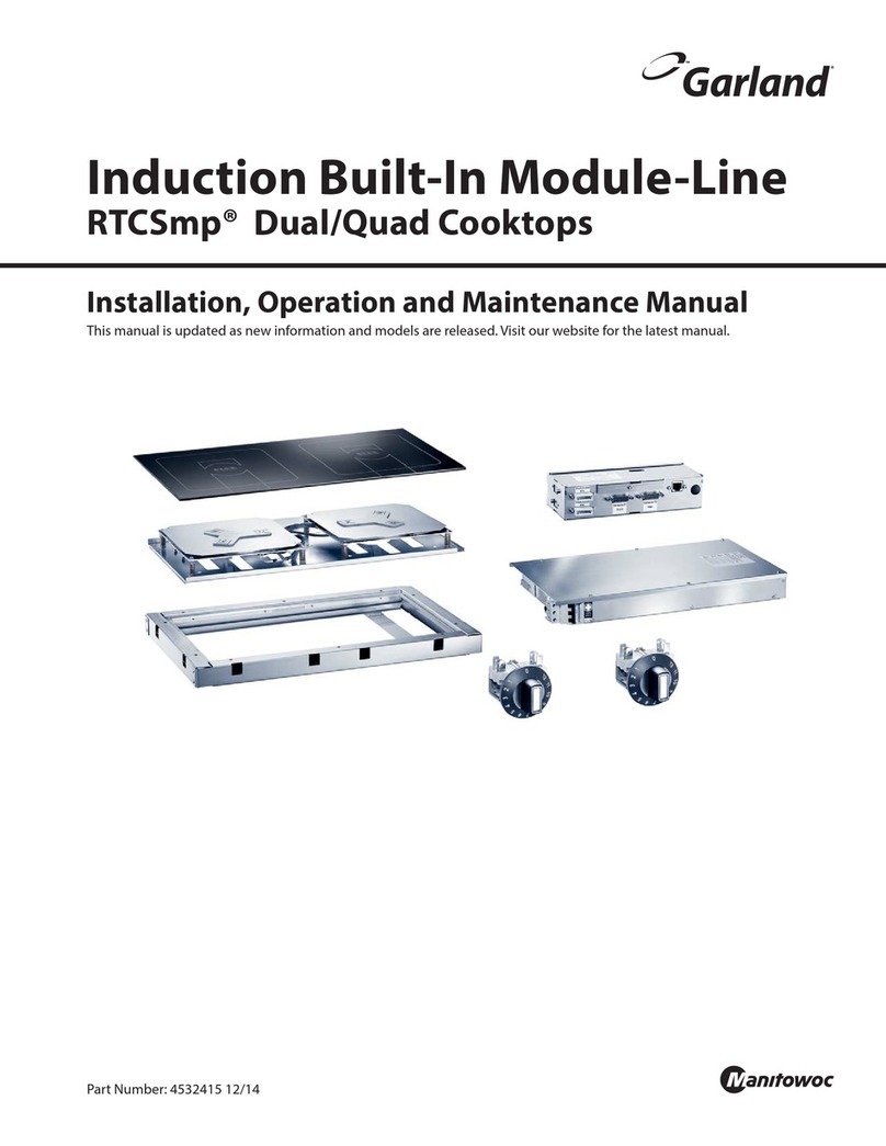
Installation and Operation Manual RTCSmp Built-In Module-Line Dual/Quad Cooktops
Part # 4532415 Rev 1 (12/12/13) 3
CONTENTS
1Safety Requirements .............................................................................................................. 5
1.1 Risk Involved By Disregarding Safety Information ..................................................................................................5
1.2 Safety Instructions for Operator .....................................................................................................................................5
1.3 Improper Use of the Equipment.....................................................................................................................................6
1.4 Unauthorized Modification and Use of Spare Parts................................................................................................6
1.5 Pan Detection.........................................................................................................................................................................7
1.6 Cooking Zone Monitoring.................................................................................................................................................7
2Application, Components Overview ..................................................................................... 8
2.1 Application..............................................................................................................................................................................8
2.2 Components and Features ...............................................................................................................................................8
3Dimensions and Technical Specifications........................................................................... 10
3.1 Rating Plate...........................................................................................................................................................................10
3.2 Nomenclature and Models .............................................................................................................................................10
3.3 Models and Components Charts..................................................................................................................................10
3.4 Electrical Specifications....................................................................................................................................................11
3.5 Operating Conditions .......................................................................................................................................................12
3.6 Compliances.........................................................................................................................................................................12
4Installation ............................................................................................................................ 13
4.1 Compartment Protection ................................................................................................................................................13
4.2 Induction Generator..........................................................................................................................................................14
4.2.1 Location..............................................................................................................................................................14
4.2.2 Ventilation .........................................................................................................................................................14
4.2.3 Dimensions........................................................................................................................................................15
4.3 Control Unit and Operation Unit/Power Switches ................................................................................................16
4.3.1 Location..............................................................................................................................................................16
4.3.2 Ventilation .........................................................................................................................................................16
4.3.3 Mounting Methods ........................................................................................................................................16
4.3.4 Dimensions – Control Unit..........................................................................................................................16
4.3.5 Dimensions Guide (Holes/Studs)..............................................................................................................17
4.4 Coil Carrier Sheet, Ceran Glass and Mounting Frame ..........................................................................................17
4.4.1 Location & Ventilation...................................................................................................................................17
4.4.2 Dimensions – Mounting Frame [for glasstop size 360x360mm]..................................................18
4.4.3 Dimensions – Mounting Frame [for glasstop size 375x650mm]..................................................19
4.4.4 Dimensions – Mounting Frame [for glasstop size 650x650mm]..................................................19
4.4.5 Dimensions – Mounting Frame [for glasstop size 360x720mm]..................................................20
4.4.6 Dimensions – Mounting Frame [for glasstop size 720x720mm]..................................................20
4.4.7 Installation Steps.............................................................................................................................................21
4.5 Models, Components and Cable Connections........................................................................................................24
4.5.1 CHART 1 – Module-Line Round Coil Dual Models..............................................................................24
4.5.2 CHART 2 – Module-Line Round Coil Quad Models............................................................................25
4.5.3 CHART 3 – Module-Line Full Coil Dual Models....................................................................................26
4.5.4 CHART 4 – Module-Line Full Coil Quad Models ..................................................................................27
4.5.5 CHART 5 – Module-Line Full and Round Coil Quad Models...........................................................28
4.6 Electrical Installation .........................................................................................................................................................29
5Function Test......................................................................................................................... 31
6Operating Instructions ......................................................................................................... 32
6.1 Proper Induction Cookware ...........................................................................................................................................32
