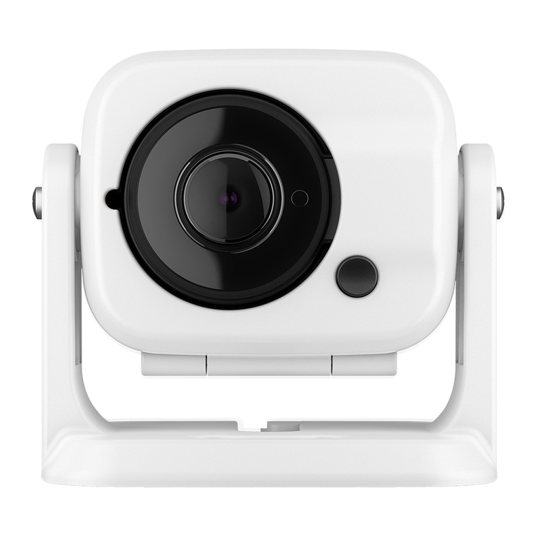
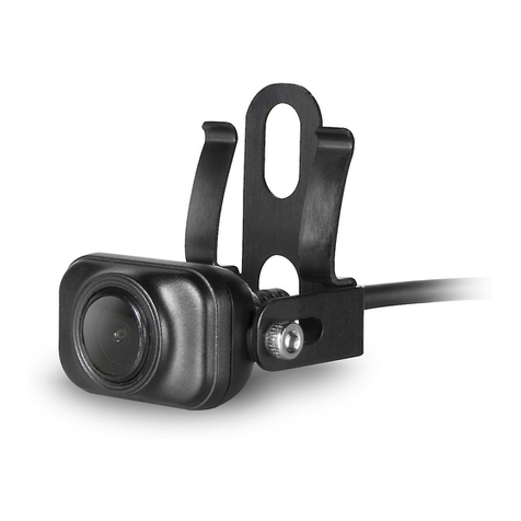
Garmin BC 30 Instruction manual

BC™ 30 Wireless Backup Camera
คู่มือ

2 BC30TM
Important Safety and Product
Information
WARNING
Failure to avoid the following potentially
hazardous situations could result in an
accident or collision resulting in death or
serious injury.
Product Environmental Programs
Information about the Garmin®product
recycling program and WEEE, RoHS,
REACH, and other compliance programs
can be found at www.garmin.com/ about-
Garmin / environment .
Declaration of Conformity
Hereby, Garmin declares that this product
is in compliance with the essential re-
quirements and other relevant provisions
of Directive 1999/5/EC. To view the full
Declaration Conformity, go to www.garmin.
com/ compliance .
Industry Canada Compliance
Category I radiocommunication devices
comply with Industry Canada Standard
RSS-210. II radiocommunication devices
comply with Industry Canada Standard
RSS-Gen. This device complies with
Industry Canada license-exempt RSS
standard(s). Operation is subject to the fol-
lowing two conditions: (1) this device may
not cause interference, and (2) this device
must accept any interference, including
interference that may cause undesired
operation of the device.
FCC Compliance
This device complies with part 15 of
the FCC Rules. Operation is subject to
following two
conditions: (1) this device may not cause
harmful interference, and (2) this device
must accept any interference received,
including that may cause undesired
operation.
This equipment has been tested and
found to comply with the limits for a Class
B digital device, pursuant to part 15 of
the FCC rules. These limits are designed
provide reasonable protectionagainst
harmful interference in a residential
installation. This quipment generates, uses,
and canradiate radio frequency energy and
may cause harmful interference to radio
communications if not installed and used in
accordance with the instructions. However,
there is no guarantee that interferencewill
not occur in a particular installation. If this
equipment does cause harmful interference
to radio ortelevision reception, which can
be determined by turning the equipment
off and on, the user is encouraged to try
to correct the interference by one of the
following measures:
• Reorient or relocate the receiving
antenna.
• Increase the separation between
equipment and receiver.
• Connect the equipment into an outlet
that is on a different circuit from GPS
device.
• Consult the dealer or an experienced
radio/TV technician for help.
This product does not contain any
user-serviceable parts. Repairs should only
be made by an authorized Garmin service
center. Unauthorized repairs or modica-
tions could result in permanent damage to
the equipment, and void your warranty and

BC30TM 3
your authority to operate this device under
Part 15 regulations.
Software License Agreement
BY USING THE DEVICE, YOU AGREE TO
BE BOUND BY THE TERMS AND CONDI-
TIONS OF THE FOLLOWING SOFTWARE
LICENSE AGREEMENT. PLEASE READ
THIS AGREEMENTCAREFULLY.
Garmin Ltd. and its subsidiaries (“ Garmin”)
grant you a limited license to use the
software embedded in this device (the
“Software”) in binary executable form nor-
mal operation of product. Title,ownership
rights, and intellectual property rights in
and to the Software remain in Garmin and/
or its third-party providers.
You acknowledge that the Software is the
property of Garmin and/or its third-party
providers and is protected under the United
States of America copyright laws and inter-
national treaties. Youfurther acknowledge
that the structure, organization, and code
of the Software, for which source code is
not provided, are valuable trade secrets
of Garmin and/or its third-party providers
and that the Software in source code form
remains a valuable trade secret of Garmin
and/or its third-party providers. You agree
not to decompile, disassemble, modify,
reverse assemble, reverse engineer, or re-
duce to human readable form the Software
or any part thereof create derivative works
based on Software. You agree not to export
or re-export the Software to any country in
violation of the export control laws of the
United States America or export control
laws any other applicable country.
Limited Warranty
This Garmin product is warranted to be free
from defects in materials or workmanship
for one year from the date of purchase.
Within this period, Garmin will, at its sole
option, repair or replace any components
that fail in normal use. Such repairs or
replacement will be made at no charge to
thecustomer for parts or labor, provided
that the customer shall be responsible any
transportation cost. This warranty does
not apply to: (i) cosmetic damage, such as
scratches, nicks and dents; (ii) consumable
parts, such as batteries, unless product
damage has occurred due to a defect in
materials or workmanship; (iii) damage
caused by accident, abuse, misuse,
water, ood, re, or other acts of nature or
external causes; (iv) damage caused by
service performed by anyone who is not
an authorized service provider of Garmin;
or (v) damage to a product that has been
modied or altered without the written
permission of Garmin, or (vi) damage to a
product that has been connected to power
and/or data cables that are not supplied
by Garmin. In addition, Garmin reserves
the right to refuse warranty claims against
products or services that are obtained and/
or used in contravention of the laws of any
country.
Our navigation products are intended to
be used only as a travel aid and must not
be used for any purpose requiring precise
measurement of direction, distance,
location or topography. Garmin makes no
warranty as to the accuracy or complete-
ness of map data.
Repairs have a 90 day warranty. If the unit
sent in is still under its original warranty,
then new warranty is 90 days or to the end
of original 1 year warranty, depending upon
which longer.

4 BC30TM
THE WARRANTIES AND REMEDIES
CONTAINED HEREIN ARE EXCLUSIVE
AND IN LIEU OF ALL OTHER WAR-
RANTIES EXPRESS, IMPLIED, OR
STATUTORY, INCLUDING ANY LIABILITY
ARISING UNDER ANY WARRANTY OF
MERCHANTABILITY OR FITNESS FOR
A PARTICULAR PURPOSE, STATUTORY
OR OTHERWISE. THIS WARRANTY
GIVES YOU SPECIFIC LEGALRIGHTS,
WHICH MAY VARY FROM STATE TO
STATE.
IN NO EVENT SHALL Garmin BE LIABLE
FOR ANY INCIDENTAL, SPECIAL, INDI-
RECT, OR CONSEQUENTIAL DAMAGES,
WHETHER RESULTING FROM THE USE,
MISUSE, OR INABILITY TO USE THIS
PRODUCT OR FROM DEFECTS IN THE
PRODUCT. SOME STATES DO NOTAL-
LOW THE EXCLUSION OF INCIDENTAL
OR CONSEQUENTIAL DAMAGES, SO
THE ABOVE LIMITATIONS MAY NOT AP-
PLY TO YOU. Garmin retains the exclusive
right to repair or replace (with a new or
newly-overhauled replacement product)
the device or software offer a full refund
of purchase price at its sole discretion.
SUCHREMEDY SHALL BE YOUR SOLE
AND EXCLUSIVE REMEDY FOR ANY
BREACH OF WARRANTY.
To obtain warranty service, contact your
local Garmin authorized dealer or call
Garmin Product Support for shipping
instructions and an RMA tracking number.
Securely pack the device a copy of theo-
riginal sales receipt, which is required as
the proof of purchase for warranty repairs.
Write trackingnumber clearly on the outside
of package. Send device, freight charges
prepaid, to any Garmin warranty service
station.
Online Auction Purchases: Products
purchased through online auctions are not
eligible for rebates or other special offers
from Garmin warranty coverage. Online
auction conrmations are not accepted for
warranty verication. To obtain service, an
original or copy of the sales receipt from
theoriginal retailer is required. Garmin will
not replace missing components from any
package purchased through an online
auction.
International Purchases: A separate
warranty may be provided by international
distributors for devices purchased outside
the United States depending on country. If
applicable, this warranty isprovided by the
local in-country distributor and this provides
service for your device. Distributor warran-
ties are only valid in the area of intended
distribution. Devices purchased theUnited
States or Canada must be returned to
the Garmin service center in the United
Kingdom, the United States, Canada, or
Taiwan for service.
Australian Purchases: Our goods come
with guarantees that cannot be excluded
under the Australian Consumer Law. You
are entitled to a replacement or refund for
major failure and compensation forany
other reasonably foreseeable loss or
damage. You are also entitled to have the
goods repaired orreplaced if the goods
fail to be of acceptable quality and failure
does not amount a major failure. The
benets under our Limited Warranty are in
addition to other rights and remedies under
applicable law in relation to the products.
Garmin Australasia, 30 Clay Place, Eastern
Creek, NSW, Australia, 2766. Phone: 1800
235 822.

BC30TM 5
BC™ 30 Wireless Backup Camera
Instructions
Introduction
WARNING
See the Important Safety and Product
Information guide in the product box for
product warnings and other important
information.
Garmin®strongly recommends having an
experienced installer with the proper
knowledge of electrical systems install the
device. Incorrectly wiring the power
cable can result in damage to the vehicle or
the battery and can cause bodily
injury.
When connecting the power cable, do not
remove the in-line fuse holder. To
prevent the possibility of injury or product
damage caused by re or overheating,
the appropriate fuse must be in place as
indicated in the product specications.
In addition, connecting the power cable
without the appropriate fuse in place will
void the product warranty.
CAUTION
Always wear safety goggles, ear protection,
and a dust mask when drilling,
cutting, or sanding.
NOTICE
When drilling or cutting, always check what
is on the opposite side of the surface.
These installation instructions do not apply
to a specic vehicle type, and are
meant as a guide when installing this
product on your vehicle. For questions
specic to your vehicle, you should contact
the vehicle manufacturer.
Device Overview
Item Description
BC™ 30 receiver cable.
The GPS device must be
powered through this cable
to communicate with the
camera.
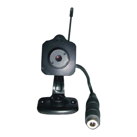
Transmitter
Camera
Camera mounting bracket
Tools Needed
• Drill and 9.09 mm, or size T (0.36 in.)
drill bit
• #2 Phillips screwdriver
• Screws, bolts, or cable ties (to secure
the transmitter)

6 BC30TM
• Solderless wire-splice connector or
solder and heat-shrink tubing
• RV sealant (optional)
Installation
Installing the Receiver
Before you can install the BC 30 receiver
cable, you must update your GPS device
to the most recent software version. Your
GPS device may not be compatible with
the BC 30 camera without the most recent
software. See your GPS device owner’s
manual or go to garmin.com/express for
more information
about updating your GPS device.
The wireless camera receiver is built into
BC 30 receiver cable included with your
wireless backup camera.
Use the BC 30 receiver cable included with
your BC 30 camera to connect your GPS
device to vehicle power. See the owner’s
manual for your GPS device for more
information about connecting the device to
vehicle power.
Camera Mounting Considerations
When selecting a location to mount the
camera, observe these considerations.
• You should test a mounting location
before you permanently mount the
camera.
• Installing the camera higher on the
back of the vehicle provides a better
viewing angle.
• The included bracket can be clipped
onto a license plate or other similar
surface, or it can be fastened to the
back of the vehicle using the included
self-tapping, panhead screws.
Transmitter Location and Wiring
Considerations
NOTICE
The transmitter is not intended to be held
or worn on your body while it is in use.
When selecting a location to install the
wireless transmitter, observe these consid-
erations.
• You should test a proposed installation
location before you permanently install
the transmitter.
• Some vehicles do not provide constant
minimum voltage to the reverse lamps.
You should use an automotive relay
when connecting the transmitter and
camera to a power source that does
not provide constant voltage.
• Although the transmitter can reliably
transmit the video signal over approx-
imately 13.5 m (45 ft.), the location of
the transmitter can affect this range.
1The closer you install the transmitter
to the receiver, the more reliable the
signal.
2The transmitter provides the best
signal when either at surface is
pointing toward the receiver.
3Dense metal or appliances in
the path of the transmitter greatly
reduce the transmission distance.

BC30TM 7
4The fewer solid objects that exist
between the path of the transmitter
and the device, the more reliable
the signal.
• If the distance between the camera and
the transmitter exceeds the length of
the included cable, additional extension
cables can be used. A 15 m (50 ft.)
extension cable can be purchased, and
more than one extension cable can
be installed. See your Garmin dealer
or go to www.garmin.com for more
information.
• The fuse holder located near the trans-
mitter is not waterproof. Installing the
fuse holder in a location that is exposed
to the elements is not recommended
• The connector between the camera
and the transmitter is not waterproof. If
you make this connection in a location
exposed to the elements, you must
make sure that the connection is
waterproof.
Testing the Camera and Transmitter
Location
1Temporarily secure the camera in the
preferred mounting location.
2Temporarily place the transmitter in
the preferred installation location, and
connect it to power and to the camera.
TIP: If you do not want to splice into
the wiring of your vehicle for this test,
you can connect the transmitter and
camera to a 12 Vdc battery.
3Test the transmitter for correct operation
by applying power to the GPS device
using the BC 30 receiver cable. If you
do not see video on the GPS device at
the preferred installation location, move
the transmitter to another location and
test it again.
4Repeat steps 2–3 until the transmitter
operates correctly.
5Test the camera view by observing the
video on the device.
6If the camera does not provide the
optimal view for your vehicle, move it to
another location and test it again.
7Repeat steps 5–6 until the camera
mounting location provides the optimal
view for your vehicle.
TIP: Make note of which direction is up
when you are testing the camera view
to ensure correct permanent installa-
tion.
Mounting the Camera
Before you permanently mount the camera,
you should test the mounting location for
the optimal view for your vehicle (page 4).
1Place the camera in the mounting
location.
2Select an option:
• If you are mounting the bracket

8 BC30TM
directly on the surface of your vehicle,
mark the locations of the two holes on
the bracket.
• If you are installing the camera on
a license plate, remove one of the
license plate screws so the hole on
the camera lines up with the hole on
the license plate.
3Secure the bracket to the vehicle using
either the included self-tapping screws
or the license-plate screw you
removed in step 2 .
4Place the camera in the bracket, and
determine the best place for the camera
cable to enter the vehicle.
5Using an appropriate drill bit, drill a
hole for the camera cable to enter the
vehicle.
6Feed the camera cable through the hole
and route it to the transmitter location.
15 m (50 ft.) extension cables can be
purchased separately, if needed.
7Secure the camera in the bracket using
the included hex bolts .
8Adjust the angle of the camera and
tighten the hex bolts using the included
hex key.
9Apply RV sealant around the cable
where it enters the vehicle (optional).
Installing the Transmitter
Before you permanently install the transmit-
ter, you must test the installation
location for correct operation (page 4).
1Secure the transmitter to the installation
location using hardware appropriate
for the location, such as screws, bolts,
or cable ties. The fuse holder located
near the transmitter is not waterproof.
Installing the fuse holder in a location
that is exposed to the elements is not
recommended.
2Connect the camera and transmitter
cables. The connector between the
camera and the transmitter is not
waterproof. If you make this connection
in a location exposed to the elements,
you must make sure that the connection
is waterproof.
3Connect the power cable from the
transmitter to a 12–24 VDC power
source, preferably a reverse lamp
using a solder less wire-splice connec-
tor (not included).

BC30TM 9
NOTE: Connecting the transmitter to
an always-on 12-24 VDC source (such
as a running lamp) instead of a reverse
lamp requires you to manually switch
power to the transmitter. The transmitter
may drain your vehicle battery if it is let
on.
4If you did not use a solder less wire-
splice connector, solder and heat-shrink
the electrical connections to protect
them from the elements.
Multiple Cameras
You can pair up to four wireless cameras
with the BC 30 receiver cable. For ex-
ample, you can pair one backup camera
installed on your vehicle and a second
backup camera installed on a trailer. From
the camera view, you can cycle through the
video feeds from all paired cameras. You
can change the order in which cameras
appear when you switch cameras.
Pairing a Transmitter with the
Receiver Cable
You can pair up to four wireless cameras
with the BC 30 receiver cable. If your cam-
era, transmitter, and receiver cable were
packaged together, they come paired from
the factory. If the transmitter and receiver
cable are properly installed and you are
not receiving video on the GPS device, you
can manually pair the transmitter and the
receiver cable again.
1Select an option:
• Place the vehicle in park.
• Turn off the steady power source
connected to the transmitter.
2Turn on the GPS device connected to
the receiver cable.
3From the GPS device, select Settings >
Backup Camera > Add New Camera.
4Follow the on-screen instructions.
Switching Cameras
You can cycle through the video feeds from
all paired cameras.
• From the camera view, select .
• The video feed from the next camera
appears, and the camera name
appears at the top of the screen
Changing the Camera Order
You can change the order in which camer-
as appear when you switch cameras.
1Select Settings > Backup Camera.
2Select a camera.
3Select Set Default Camera.
A list of paired cameras appears.
4Drag each camera to the desired
location in the list. When you switch
cameras from the camera view, the
cameras appear in the listed order,
from top to bottom. The camera at the
top of the list is the default camera and
appears rst each time the camera view
appears.
Renaming a Camera
You can change the name that appears
above a camera in the camera view. You
should use a descriptive name that clearly
identies the location of the camera.
1Select Settings > Backup Camera.

10 BC30TM
2Select a camera.
3Select Rename.
Removing a Paired Camera
If you have already paired four cameras
with your BC 30 receiver cable, you must
remove a paired camera before you can
pair a new one.
1Select Settings > Backup Camera.
2Select a camera.
3Select Unpair.
Viewing Wireless Camera Video
Before you can view video from your wire-
less camera, you must install the camera,
transmitter, and receiver cable. See the
installation instructions for your wireless
camera for more information.
Your GPS device shows video from your
paired wireless cameras in different ways,
depending on how the camera transmitter
is connected to power.
1Select an option to show video:
• If the transmitter is connected to a
reverse lamp (recommended), place
the vehicle into reverse. The device
automatically shows video from the
backup camera.
• If the transmitter is connected to a
running lamp or other steady 12 Vdc
source, select on the device to
show video from the backup camera.
2Select an option to resume normal
device operation:
• If the transmitter is connected to
a reverse lamp (recommended),
take the vehicle out of reverse. The
device automatically resumes normal
operation.
• If the transmitter is connected to a
running lamp or other steady 12 Vdc
source, select on the device to
resume normal operation.
Guidance Lines
NOTICE
The guidance lines feature is intended
for informational and reference purposes
only. You are responsible for maintaining
awareness of your surroundings.
Guidance lines provide an approximate
visual representation of the vehicle’s path
when in reverse. To provide the most accu-
rate reference, you must align the guidance
lines for each backup camera. You should
not use the guidance lines feature if you
have not aligned the guidance lines.
Aligning the Guidance Lines
For best reference, the guidance lines
should be aligned to reect the outside
edges of the vehicle. You should align the
guidance lines separately for each backup
camera.
1Position the vehicle with one side
closely aligned to a curb, driveway, or
parking stall lines.
• You may want to position the vehicle
in the center of a parking stall, and
then pull forward into the next stall.
This allows you to use the parking
stall lines in the rear of the vehicle as
reference points for alignment.

BC30TM 11
• The curb, driveway, or parking stall
lines should be clearly visible on the
device.
2From the main menu, select Settings >
Backup Camera.
3Select the camera to adjust, and select
Guidance Lines > Adjust Guidance
Lines.
4Use the arrows in the corners of the
screen to move the guidance lines to
match the angle and position of the
curb, driveway, or parking stall lines.
• The guidance lines should appear di-
rectly on top of your reference points.
5Use the arrows in the center of the
screen to move the guidance lines up or
down. The red section of the guidance
lines should be aligned with the rear of
your vehicle.
6If necessary, reposition the vehicle
with the other side closely aligned to
a curb, driveway, or parking stall lines,
and repeat the alignment process. You
should attempt to keep the guidance
lines symmetrical, even if your vehicle
is not in perfect alignment with the curb,
driveway, or parking stall lines.
7Select after alignment is complete.
Showing or Hiding Guidance Lines
1From the camera view, select >
Guidance Lines.
2Select or clear the Show Guidance
Lines check box.
Restoring Alignment
You can reset the guidance lines to their
default alignment.
1Select Settings > Backup Camera.
2Select the camera to adjust, and select
Guidance Lines > Restore.
Appendix
Specications
Camera and
transmitter input
voltage
From 9 to 28 Vdc
Transmitter fuse
Transmitter fuse 500 mA, fast-blow
Camera and
transmitter current
usage
150 mA at 12 Vdc
Camera and trans-
mitter waterproof
rating
IPX7*
Camera view angle 170 degree (Diag-
onal)
Camera Minimum
illumination
1 lux
Camera tempera-
ture range
From -40° to 85°C
(from -40° to 185°F)

12 BC30TM
Transmitter and
receiver cable
temperature range
From -20° to 70°C
(from -4° to 158°F)
Receiver cable
input voltage
From 10 to 24 V
Receiver cable
fuse
2 A, 250 V
*The device withstands incidental exposure
to water of up to 1 m for up to30 min. For
more information, go to www.garmin.com/
waterrating.

BC30TM 13
安全及產品資訊須知
警告
未能避免下列潛在危險情況,可導
致死亡或嚴重傷害。
如需Garmin產品回收計劃及
WEEE、RoHS、REACH和其他符
合性計劃的詳細資訊,請參見網站
Garmin.com/aboutGarmin/environ-
ment。
Garmin謹此聲明本產品符合指令
1999/5/EC必要的要求及其他相關條
款。
第一類無線電通訊設備,符合加拿
大工業標準RSS-210,第二類無線
電通訊設備,符合加拿大工業標準
RSS-310。
本裝置符合FCC通則之第15部分。
裝置操作將受限於以下兩個條件:
(1)裝置不得引起有害干擾。(2)裝置
必須能接受任何接收到的干擾,包
括引起無用操作的干擾。本設備經
測試證實符合FCC通則第15部分所
定義之B級數位裝置限制。該限制是
為了提供住宅裝置對有害干擾的合
理保護。本設備可產生、使用及發
射射頻能量。若未依照指示進行安
裝及使用,可能對無線電通訊引起
有害干擾。
然而,在某些裝置上無法保證不會
發生干擾現象。若本設備對於無線
電或電視接收確實引起有害干擾(可
將設備關閉再開啟以進行判定),
建議您採用以下方式對干擾進行修
正:
• 將接收天線調整方向或改變放置
地點。
• 加大設備與接收器之間距離。
• 分開設備及GPS裝置所使用的插
座,使其不在同一電路。
• 洽詢經銷商或有經驗的無線
電/TV技師請求協助。
本產品內不含任何使用者可自行保
養的零件。不得在非Garmin授權
的服務中心進行檢修。經非授權之
檢修或修改可能造成設備永久性
損壞,且將喪失您的產品保固及
Part15法規下授權給您的本裝置操
作權利。
本產品BC30™,僅遵循中華民國
國家通訊傳播委員會所頒佈低功率
電波輻射性電機管理辦法規範,並
經驗證通過合格,請使用者遵循相
關電信法規以避免違反規定受罰。
若使用者欲攜帶本機至其它國家應
用,也請遵循該地區或國家之相關
法令限制。根據國家通訊傳播委員

14 BC30TM
會低功率電波輻射性電機管理辦法
規定:
1第十二條
經型式認證合格之低功率射頻電
機,非經許可,公司、商號或使
用者均不得擅自變更頻率、加大
功率或變更原設計之特性及功
能。
2第十四條
低功率射頻電機之使用不得影響
飛航安全及干擾合法通信;經發
現有干擾現象時,應立即停用,
並改善至無干擾時方得繼續使
用。前項合法通信,指依電信法
規定作業之無線電通信。低功率
射頻電機須忍受合法通信或工
業、科學及醫療用電波輻射性電
機設備之干擾。
在您使用BC30™無線倒車攝影鏡頭
組前,您需同意下列有關本機台軟
體之授權限制與聲明,請您務必仔
細閱讀下列條文。
在您購買及使用BC30™無線倒車攝
影鏡頭組時,台灣國際航電股份有
限公司(Garmin Corporation)僅
同意您使用已內建於該產品之中、
英文版軟體工具,亦即該軟體原始
碼之所有權、智慧財產權,仍均屬
於台灣國際航電股份有限公司所擁
有。
上述產品之中、英文版軟體工具之
財產所有權,均受到美國政府、中
華民國政府與全球智慧財產權的相
關公約保護,全部之軟體程式結
構、組態、原始編碼之商業價值,
均歸屬 Garmin 商業機密。您同意不
自行將這個軟體重新編譯、組合、
修正、轉換組合、轉換工程或降低
人們的使用功能、產生偏差功能等
行為,您亦同意不自行出口或轉口
本軟體至其他尚屬美國政府明文禁
運地區的國家或地區。請您遵守上
述聲明與條款。
本Garmin產品從採購日起保證一年
在材料或製造工藝上無任何瑕疵。
在此期間Garmin將依其選擇對正常
使用下發生故障的元件進行檢修或
予以更換。對於此類檢修或更換若
客戶可負責運費部分,則客戶將可
享用免費檢修零件或工資。本保固
不適用:(i)表面損壞,如刮痕、凹
痕及凹陷。(ii)如電池等類消耗品,
但若為材料或製造工藝瑕疵造成產
品損壞者除外。(iii)因意外、濫用、
誤用、水、淹水、火災或其他天災
或外來因素造成的損壞。(iv)由非
Garmin授權保養人員檢修後造成之
損壞。(v)未經Garmin書面同意,
逕自修改或改變產品造成之損壞。
此外,對違反任何國家法律而取得
及/或使用之產品或服務,Garmin
保留拒絕保固聲請的權利。本產品
使用原意僅在於輔助行駛,不得作
為測定精確方向、距離、地點或地
形的任何目的使用。Garmin對本產

BC30TM 15
品內含地圖資料的準確性或完整性
不予任何保證。此處所述之保固及
補救條款為排他性,且取代所有其
他明示性或暗示性或法令的保固條
件,包括在某特殊目的、法令規定
或其他情況下任何商品的適售性或
適用性保固衍生的任何責任。本保
固提供您特定的法律權利,但此權
利可能每州各有不同。對於任何意
外、特殊、間接或衍生性損壞(可
能起源於使用、誤用、不會使用或
產品瑕疵)Garmin將概不負責。有
些州不容有排除附帶或衍生性損壞
賠償,因此上述限制對您可能不適
用。Garmin保留檢修或更換(新產品
或全新大修過的替換產品)裝置或軟
體權利,或有權利選擇退回完整採
購價款。
對於任何違反保固條款者,此為唯
一且排他之補救措施。申請保固服
務時請洽詢您當地的Garmin授權經
銷商,或電洽Garmin產品支援部索
取裝運指示及RMA追蹤碼。請將裝
置包裝妥當並附上原始銷貨收據影
本,以此作為申請保固檢修必要之
購貨證明。在外部包裝面請清楚標
示您的追蹤碼,預付運費後將裝置
寄送至任何Garmin的保固服務站。

16 BC30TM
開始使用
警告
關於產品風險以及重要資訊,請詳
閱《GARMIN安全及產品資訊須
知》。
Garmin®強烈建議,由具備正確電
氣系統知識且有經驗的安裝人員來
安裝裝置。電源線連接不當,可能
導致車輛或電瓶損壞,甚至人身傷
害。
連接電源線時,請勿移除內嵌的保
險絲座。為避免因起火或過熱而造
成人身傷害或產品損壞,請務必按
產品規格安裝適當保險絲。此外,
若未安裝適當保險絲即連接電源
線,將使產品保固失效。
注意
進行鑽孔、切割或打磨時,務必穿
戴護目鏡、耳罩和防塵口罩。
注意
進行鑽孔或切割時,務必確認另一
面有無任何物品。
以下安裝指示不限於特定車款,僅
供安裝此產品於車輛上時參考之
用。如有車輛問題,應聯絡車輛製
造商。
外觀介紹
項目 說 明
BC™30無線訊號接收電源
線。
GPS 裝置必須透過此連接線
供電,才可與攝影鏡頭進行
通訊。
無線訊號發送器。
攝影鏡頭。
攝影鏡頭固定支架
所需工具
• 電鑽、9.09 mm或T 型(0.36 吋)
鑽頭
• 2 號十字螺絲起子
• 螺絲、螺栓或束線(用於固定發
送器)
• 免焊接頭線夾,或焊錫與熱縮
套管
• RV 密封膠 (選用)

BC30TM 17
安裝說明
安裝 BC 30 無線訊號接收電源線之
前,必須更新至最新版軟體。若未
安裝最新版軟體,可能無法與BC 30
攝影鏡頭相容。如需更新GPS裝置
的詳細資訊,請查閱GPS裝置官網
產品頁說明。
使用 BC 30 攝影鏡頭組隨附的 BC
30無線訊號接收電源線,將GPS裝
置連接至汽車車充電源孔。
如需將裝置連接至汽車電源的詳細
資訊,請查閱各GPS裝置的使用手
冊。
在選擇攝影鏡頭架設位置時,請注
意下列事項:
• 應先針對架設位置進行測試,才
將攝影鏡頭架設定位。
• 攝影鏡頭應安裝於車輛後方較高
的位置,以取得較佳拍攝視角。
• 隨附的支架可夾在車牌或其他類
似的平面上,也可使用隨附的螺
絲固定於車輛後方。
注意
發送器不可握拿或配戴在身上使
用。
在選擇無線發送器的安裝位置時,
請注意下列事項:
• 應先針對所需安裝位置進行測
試,才將發送器安裝定位。
• 部分車輛無法為倒車燈提供穩定
的最低必要電壓,因此,若將發
送器及攝影鏡頭連接至使車輛無
法提供穩定的電壓電源,應選購
額外安裝繼電器。
• 發送器可穩定發送影像訊號的最
遠距離約為 13.5 公尺 (45 呎),
但發送器的安裝位置可能影響此
距離。
1發送器與接收器之間的距離越
短,訊號越穩定。
2發送器任一平面朝向接收器
時,訊號最佳。
3訊號發送路徑中若有高密度的
金屬或設備 ,將大幅縮短發
送距離。
4發送器與裝置之間的堅硬實心
物體越少,訊號越穩定。
如果攝影鏡頭與發送器間的距離超
過連接線的長度,可另外選購專用
延長線,且可同時使用多條進延長
線。如需詳細資訊,請洽詢 Garmin
經銷商或前往 Garmin.com.tw。

18 BC30TM
• 發送器旁的保險絲座不防水。不
建議將保險絲座安裝在曝露於潮
濕環境的位置。
• 攝影鏡頭與發送器的連結線材接
頭皆不防水。若將接點安裝在曝
露於潮濕環境的位置,請務必做
好防水動作。
1暫時將攝影鏡頭固定於所要的架
設位置。
2暫時將發送器固定於所要的安裝
位置,並將其連接電源及攝影鏡
頭。
小秘訣:如果測試時不想從車輛配
線分接電源,可將發送器及攝影
鏡頭連接至 12 V DC 電池。
3用BC 30 無線訊號接收電源線為
GPS裝置供電,測試發送器是否
正常運作。
• 如果固定於所要安裝位置
後,GPS裝置未顯示影像,請
將發送器移至其他位置並再試
一次。
4重複進行步驟2至3,直到發送器
正常於GPS裝置顯示影像。
5觀察裝置上的影像,測試調整攝
影鏡頭視野。
6如果攝影鏡頭無法為您的車輛提
供最佳視野,請將攝影鏡頭移至
其他位置並再試一次。
7重複進行步驟5至6,直到攝影鏡
頭架設位置提供最佳視野為止。
小秘訣:測試攝影鏡頭視野時,請
務必將鏡頭朝上,以便正確進行
永久安裝。
永久架設攝影鏡頭前,應先測試架
設位置能否取得車輛最佳視野。
1 將攝影鏡頭 置於架設位置。
2選取一個選項:
如果要將攝影鏡頭固定架直接架
設於車輛表面,請在車輛表面上
標出兩個支架螺絲孔 的位置。
如果要將攝影鏡頭固定架安裝於
車牌,請鬆開其中一個車牌螺
絲,然後讓攝影鏡頭螺絲孔對準
車牌螺絲孔。
3使用隨附的螺絲 ,或是步驟2
中拆下的車牌螺絲 ,固定在車
輛上。
4將攝影鏡頭放在固定架上,判斷
攝影鏡頭連接線 拉入車內的最
佳位置。

BC30TM 19
5使用適當的鑽頭,鑽一個可將攝
影鏡頭連接線拉入車內的小洞。
6將攝影鏡頭連接線穿過小洞,然
後拉到發送器的位置。
可視需要選購延長線。
7使用隨附的內六角螺絲 將攝影
鏡頭固定在固定架。
8調整攝影鏡頭角度,使用隨附的
板手鎖緊螺絲。
9在連接線拉入車內的小洞周圍塗
上RV 密封膠 (選用)。
永久安裝發送器之前,必須先對安
裝位置進行測試,確保其運作正
常。
1針對該位置選用適當組裝零件 (如
螺絲、螺栓或束線),將發送器固
定於安裝位置。
• 發送器旁的保險絲座不防水。
不建議將保險絲座安裝在暴露
於潮濕環境的位置。
2連接攝影鏡頭與發送器連接線。
• 攝影鏡頭與發送器的連結線材
接頭皆不防水。若將接點安裝
在曝露於潮濕環境的位置,請
務必做好防水動作。
3使用免焊接頭線夾(未隨附),將
發送器的電源線 連接至12-24V
DC 電源。建議連接至倒車燈電
源。
備 註:如果不將發送器連接至倒
車燈,而是連接至永不斷電的12-
24V DC 電源 (例如大燈),則需要
另行安裝手動開啟發送器電源開
關。若讓發送器保持隨時開啟,
有可能會耗盡車輛電瓶的電力。
4 若未使用免焊接頭線夾,請用焊
錫連接並使用熱縮套管,以避免
接點暴露於外部環境。
多台攝影機
BC 30 無線訊號接收電源線可以配
對四個BC 30 攝影鏡頭。例如,您
可以安裝配對一個倒車鏡頭在您的
車輛,另一個安裝在拖車上。透過
攝影鏡頭影像,您可以循環播放配
對的攝影鏡頭。您也可以更換顯示
順序。
BC 30 無線訊號接收電源線最多可
以配對四個BC 30 攝影鏡頭。如果
您購買的是無線倒車攝影鏡頭組,
出廠前接收電源線與發送器已經完
成配對。如果沒有正確配對,您可
以手動重新配對。

20 BC30TM
1選擇一個選項:
• 在公園停車。
• 關閉連接到發送器的電源。
2開啟連接接收電源線的GPS裝
置。
3從GPS裝置,點選 設定 > 倒車攝
影機 > 新增攝影機。
4依照螢幕指示操作。
切換攝影鏡頭
您可以循環播放已配對的攝影鏡
頭。
• 從攝影鏡頭影像,點選 。
• 畫面會顯示下一個攝影影像並在
畫面上方顯示鏡頭名稱。
變更順序
您可以變更攝影鏡頭循環播放的順
序。
1點選 設定 > 倒車攝影機。
2選擇攝影鏡頭。
3點選 設定預設攝影機。
• 在配對的攝影機列表點選。
4在列表上拖曳攝影機到希望的順
序。
• 在列表上變更攝影機順序,最
上方的為預設攝影機畫面,於
每次循環播放時最先出現。
重新命名
您可以變更顯示在攝影畫面上的顯
示名稱。並使用描述方式說明攝影
鏡頭的位置。
1點選 設定 > 倒車攝影機 。
2選擇攝影鏡頭。
3選擇 重新命名 。
移除配對
如果您的BC 30 無線訊號接收電源
線已經配對四個BC 30 攝影鏡頭。
在您要配對新的攝影鏡頭前,必須
先取消已經配對的攝影鏡頭。
1點選 設定 > 倒車攝影機 。
2選擇攝影鏡頭。
3選擇 取消配對 。
查看無線倒車攝影鏡
頭組影像
在GPS裝置查看無線倒車攝影鏡頭
拍攝的畫面前,您必須安裝攝影鏡
頭、無線訊號發送器和無線訊號接
收電源線。
無線倒車攝影鏡頭畫面在GPS顯示
的方式,依據您如何連結發送器的
電源。
1選擇一個選項,以顯示畫面:
• 如果發送器連接倒車燈電源(
建議),倒車時GPS會自動顯
示畫面。
Other manuals for BC 30
3
Table of contents
Languages:
Other Garmin Digital Camera manuals

Garmin
Garmin GDR 190 User manual
Garmin
Garmin BC 20 User manual
Garmin
Garmin BC 50 User manual

Garmin
Garmin BC 50 NIGHT VISION User manual

Garmin
Garmin GC 14 User manual
Garmin
Garmin GC 200 User manual
Garmin
Garmin BC 40 Instruction manual
Garmin
Garmin VIRB Series User manual
Garmin
Garmin DASH CAM 56 User manual
Garmin
Garmin GC 12 User manual
