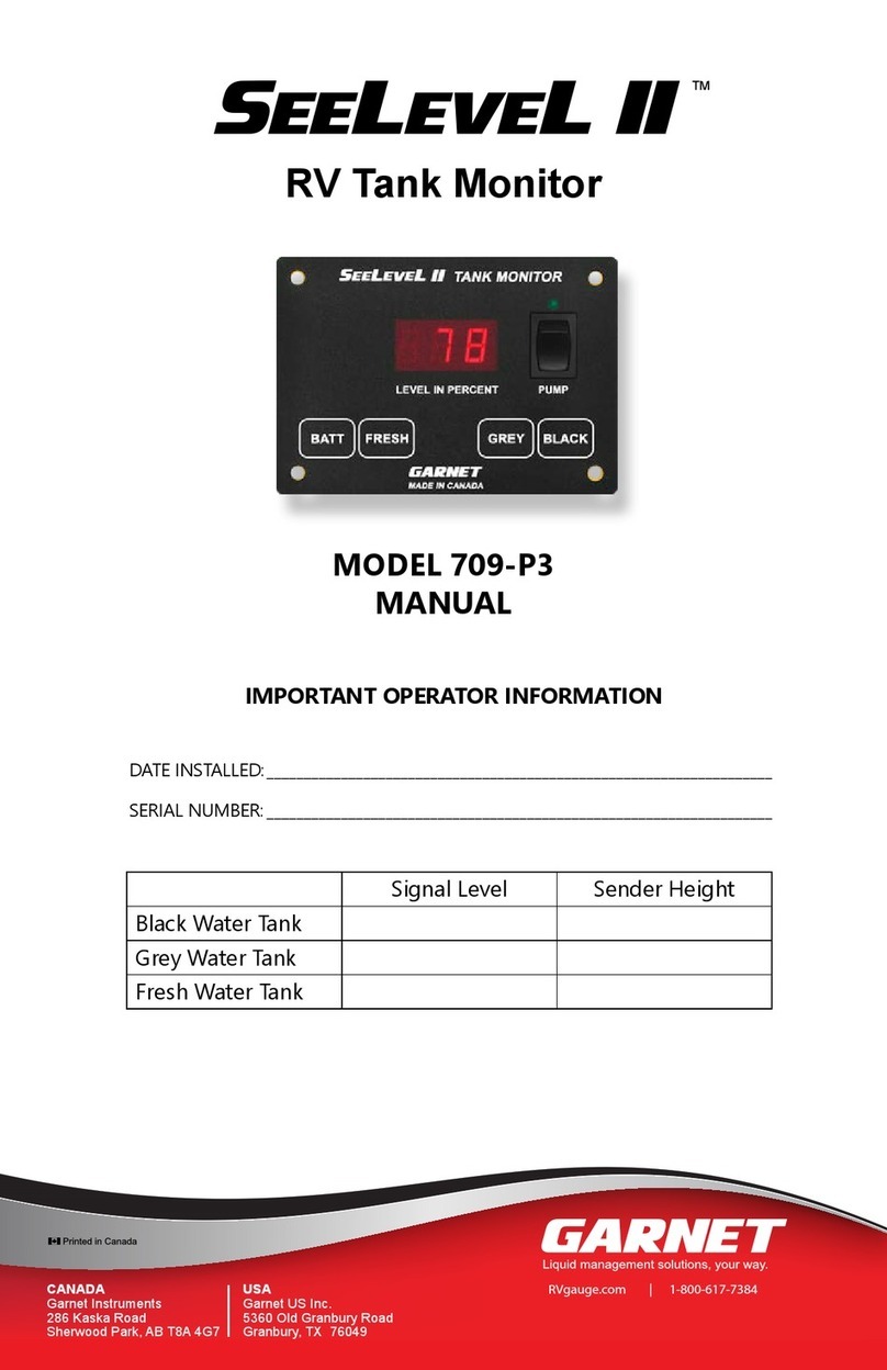
Garnet 900D6 DUAL User manual

Page 1
900D6D Manual
IMPORTANT OPERATOR INFORMATION
DATE INSTALLED:_______________________________________________________________________________
UNIT NUMBER:_________________________________________________________________________________
COMPARTMENT: _______________________________________________________________________________
DISPLAY CALIBRATION UNITS (e.g. inches, gallons): ___________________________________________
MINIMUM TANK READOUT: ___________________________________________________________________
MAXIMUM TANK READOUT: ___________________________________________________________________
ALARM POINT (IF APPLICABLE):________________________________________________________________
SPILLSTOP EMPTY POINT (IF APPLICABLE): ____________________________________________________
SPILLSTOP HORN POINT (IF APPLICABLE): _____________________________________________________
SPILLSTOP SHUTDOWN POINT (IF APPLICABLE): ______________________________________________
AUTOMATIC ALARM: WARNING LEVEL: ____________________________________________________
EMPTY LEVEL: ________________________________________________________
Printed in Canada
www.garnetinstruments.com
MODEL 900D6 DUAL
MANUAL
IMPORTANT OPERATOR INFORMATION
DATE INSTALLED:____________________________________________________________________
TANK NUMBER: _____________________________________________________________________
MINIMUM TANK READOUT: ________________________________________________________
MAXIMUM TANK READOUT: ________________________________________________________
ALARM
HIGH VOLUME
ALARM
LOW VOLUME
Normally Open or
Normally Closed
ALARM 1 □NO □NC
ALARM 2 □NO □NC
ALARM 3 □NO □NC
ALARM 4 □NO □NC
SEELEVEL II TM
Tank Fluid Monitor

Page 2 900D6D Manual
Table of Contents
CHAPTER 1 - OVERVIEW.............................................................................................3
CHAPTER 2 - SYSTEM DESCRIPTION .....................................................................4
CHAPTER 3 - KEYPAD OPERATING INSTRUCTIONS.........................................8
CHAPTER 4 - INSTALLATION GUIDE..................................................................... 18
CHAPTER 5 - TROUBLESHOOTING GUIDE......................................................... 19
CHAPTER 6 - SERVICE & WARRANTY INFORMATION.................................. 21
CHAPTER 7 - SPECIFICATIONS ............................................................................... 22
CHAPTER 8 - MASTER CODE................................................................................... 23
GARNET
SEELEVEL II TM
Tank Fluid Monitor
MODEL 900-D6 DUAL
900D6 Dual Manual_v2.2 9-May-2017

Page 3
900D6D Manual
Congratulations on purchasing the Garnet Instruments Model
900D6 SEELEVEL II TM Fluid Monitor for Tanks. The SeeLeveL
II represents the latest in state of the art liquid monitoring
equipment for stationary tank applications. The SEELEVEL II is
designed for reliable and accurate level, volume, and temperature
measurement of sour or sweet crude oil, chemicals, acids, water, or
fuels. The liquid level is determined by sensing the position of a
magnetic oat using a series of reed switches arranged in a vertical
sensing bar. This technology has no moving parts except for the
oat, and can operate over a range of product temperatures from
-40°C to +90°C (-40°F to +194°F). The temperature is sensed by
semiconductor temperature probes spaced every 16 inches along
the inside length of the bar.
The SEELEVEL II components are weatherproof to allow installation
in any environment. Most monitor functions operate entirely
on internal batteries, so external power is not required in many
applications. The displays can be continuously seen in the daytime
and are visible at night with the push of a button. All functions
on the gauge, including calibration, alarms, and security, can be
programmed with the built in keypad. Remote communications
and alarms are available via terminal blocks inside the gauge
display.
CHAPTER 1 - OVERVIEW

Page 4 900D6D Manual
The SeeLeveL II consists of a sender bar, a donut shaped oat,
a ber optic interconnect cable, and a display. The sender
bar is mounted vertically in the tank with the oat sliding up and
down around it in accordance with the uid level. The sender bar
sends the uid level and temperature information via ber optic
cable to the display. The temperature is the average value of the
sensors below the uid level, so the air temperature above the
uid is ignored. The display shows the level, volume, temperature
and alarm status to the user, and provides alarm and remote
communication outputs.
The Sender and Float: The sender bar consists of a exible 3/4
inch aluminum reinforced polyethylene pipe or a 1 inch 316
seamless stainless steel tube with a head at the top end where the
ber optic cable connects. It is secured at the top of the tank by
a compression tting just below the head, and is secured at the
bottom of the tank by an anchor tting. The compression tting
provides the seal where the sender exits the tank, and the anchor
keeps the sender bar vertical in the tank. This mounting system
allows the sender bar to be removed from the top of the tank for
servicing without having to go into the tank.
The oat is molded from polyethylene for high chemical resistance
and durability. A stainless steel oat is also available. The oat
contains magnets which activate reed switches inside the sender
bar to indicate the level of the uid, which is measured with a
resolution of 1/4” throughout the tank. The activated switches
are detected by a microprocessor at the top of the bar. The use
of a digital rather than analog sensing technique lowers power
consumptiontopermitbattery operationand ensureshigh accuracy
with no drift or degradation. The sender optically transmits the
level and temperature information every two seconds via an LED
located in the head, so the LED will appear to ash once every two
seconds. There are electronic temperature sensors located every
16 inches inside the bar, one sensor is sampled and a new average
is obtained every 2 seconds. For a 50 foot long bar, there are 37
sensors, which would require 74 seconds to sample all of them.
All of the sensors below the uid level are included in the average;
the sensors above the uid level are excluded, so the average
temperature is for the uid only, not the air or vapor above the
uid. The microprocessor operates from a 3.6 volt lithium battery
module giving over 5 years of life, the battery module can be eld
replaced with simple hand tools.
CHAPTER 2 - SYSTEM DESCRIPTION

Page 5
900D6D Manual
IMPORTANT NOTICE: SENDER BAR LIMITS OF RESISTIVITY
The temperature of the product in the tank should be limited to
approximately +90°C (+194°F). Damage to the oat and sender
bar can occur if this value is exceeded.
The oat and tube used in the manufacturing of the sender bar
is polyethylene. It should be noted that certain corrosive
products, as well as high concentrations of acid products, may
attack the polyethylene and cause perforations to develop.
It is the operator’s responsibility to determine the products
compatibility with the sender bar.
WARNING: Perforation of the sender bar or heat damage is
not warrantable.
The Fiber Optic Cable: The LED on the sender is connected to
a plastic ber optic cable which carries the information to the
display. The ber is used to maintain electrical isolation between
the sender bar and the display, this way an electrical spark cannot
occur in the tank, so no explosion hazard can exist with ammable
liquids. The ber optic cable is housed in a conduit for protection,
and it can be disconnected at both ends for servicing. The type
of ber used has a 1.0 mm core diameter, and an outer jacketed
diameter of 2.2 mm. It can be cut with a sharp knife; no stripping
or other special preparation is needed.
The Display: The display receives the optical information from
the sender, translates the signal into volume and temperature
information to show to the user, generates digital signals for
remote communication, and controls the alarm outputs.
Display LCDs: The display has 4 separate LCDs to show information.
These LCDs have excellent daytime visibility, and have a backlight
to allow night viewing as well. The backlight turns on whenever
the ENTER/LIGHT button on the keypad is pressed.
The dual displays show the volume of the uid of two tanks in
the upper LCDs. The ve numbers can be programmed to show
any volume units (for example, barrels), so up to 99,999 can be
shown, with the decimal able to be set as 9.9999, 99.999, 999.99,
9999.9, or 99999 with no decimal. The volume is programmed
using the keypad. A chart showing inches of level versus barrels
of volume for the tank is required. If the tank has straight vertical
sides so that the volume per inch of depth is constant throughout
the tank, then the volume per inch can be entered and the display
will calculate all of the inch versus volume increments.

Page 6 900D6D Manual
Even though the gauge has 1/4” resolution, it is only necessary to
program the volume for each whole inch; the display calculates
the volume at the 1/4”, 1/2”, and 3/4” points. Programming is a
two step process, rst the chart of volume for the inches of level is
entered, and then the offset has to be set to account for variations
in tank height and sender mounting position.
The lower LCDs shows the temperature of the products in each
tank. The temperature shown is the average of the sensors below
the uid level, eliminating the temperature of the air above the
uid and therefore not effecting the temperature reading. The
display can be programmed via the keypad to read out in degrees
Fahrenheit or Celsius.
If the INCHES button is pressed, the LCDs show the level of the
tanks in inches, based on the product level.
If the ALARMS button is pressed, the LCDs show the current
alarm status, based on the product level and the alarm set points.
Alarms 1 to 4 are shown as “1234” on the LCD; if the alarm output
is active, the number is shown and if the alarm output is inactive,
the number is not shown. So for example, if the “12 4” is shown,
it means that alarms 1, 2, and 4 are active, and 3 is not.
If the BATTERY button is pressed, the display will show the
condition of the sender battery and the display batteries. The
battery conditions can be “Good”, “FAIr”, or “Poor”. If the batteries
are “FAIr”, they should be replaced soon, and if they are “Poor”
then the gauge may not function properly and the batteries must
be replaced immediately.
The LCDs take on different roles during programming, but this is
covered in the next chapter.
Display Keypad: The keypad consists of the 16 buttons on the
front of the display. The keypad is used for the following functions:
• To show inches, alarms, and battery condition as described
above.
• To turn on the LCD backlight.
• To turn the gauge display on or off.
• To select °F or °C for the temperature display.
• To set the alarm points.
• To test the alarms.
• To program the gauge calibration.
• To enter the security codes which control access to the various
gauge functions.

Page 7
900D6D Manual
Display Batteries: A set of four alkaline ‘D’ cells in the display
enclosure powers all gauge display functions. This allows for total
stand alone operation of the gauge. The battery pack should
last from 3 to 4 years, depending on usage of the LCD backlight.
A display with the optional 901D6 cellular or 904D6 satellite
communications board use 8 ‘D’ cells. The battery life of the 901
cellular, 903 wireless, and 904 satellite very depending on their
congured update frequency. The batteries can be eld replaced
with simple hand tools, and all programming is retained when the
batteries are removed. The 902 modbus option requires external
12 or 24 volt power.
Display Alarms: The display has 4 alarm points which can each
be programmed via the keypad to turn on or off at any level in
the tank. The alarm outputs are transistors which conduct to
ground, and are rated at 100mA at 24 volts. These outputs are for
connecting to an external alarm system which has been designed
to work with this type of output. The alarm outputs and ground
are available at a terminal block inside the display enclosure.
WARNING: The use of alarm points is entirely at the owner’s
risk due to the nature of connecting external horns or lights,
the reliability of external horns or lights, and the requirement
for external switches to disarm them.
Display Enclosure: The entire display is enclosed in a weatherproof
berglass enclosure with a hinged cover. This provides all weather
operation and easy access to the internal batteries. The enclosure
must always be kept tightly closed when not changing batteries to
prevent water damage to the electronics. Never open the display
enclosure when rain or water could enter the box.

Page 8 900D6D Manual
The keypad consists of the 16 buttons on the front of the display,
and is used for the following functions:
1. To show inches, temperature, alarm status, and battery
condition as described in the previous chapter.
2. To turn on the backlight.
3. To test the alarms.
4. To turn the gauge display on or off.
5. To select Fahrenheit or Celsius for the temperature display.
6. To program the SMS phone number for alarm updates.
(901 only)
7. To set gauge identication numbers of each tank.
8. To view the satellite IMEI identication number. (904 only)
9. To view the last eight radio error codes.
10. To view radio signal strength level. (901,902,904 only)
11. To set the serial communication on or off.
12. To set the alarm points.
13. To select SMS phone on or off. (901 only)
14. To select data upload on or off. (901,904 only)
15. To set the gauge offset (the zero point).
16. To enter a linear calibration factor for the volume display.
17. To enter a point by point calibration table for the volume
display.
18. To allow the memory to be copied or programmed remotely.
19. To set the serial output to match optional board installed.
20. To select satellite data logging on or off. (904 only)
21. To view satellite diagnostic values. (904 only)
22. To set the cellular TCP address destination and port. (901 only)
23. To enter the 4 digit short user code which permits access to
functions 4 to 10 only.
24. To enter the 6 digit long user code which permits access to
functions 11 to 14 only.
25. To enter the 8 digit master code which permits authorized
personnel to set the user codes and to access functions 15
to 22.
CHAPTER 3 - KEYPAD OPERATING INSTRUCTIONS

Page 9
900D6D Manual
Since the operation of the gauge can be severely compromised
by improper keypad use, there are security features incorporated
into the gauge. These security features also allow the owner of
the tank to better manage rentals and billing by controlling access
to the gauge functions. For example, using the Short User Code,
the tank owner may choose to turn off the gauge display for rental
customers that do not want to rent the tank gauging system.
In this case the gauge will display OFF instead of showing tank
volume readings. When using the 901 cellular option, the tank
owner may also turn off the data upload and SMS phone alarms
using the Long User Code. When using the 904 satellite option,
the tank owner may turn off the satellite data uploads by choosing
SATELLITE OFF using the Master Code. When this is done only GPS
location data is uploaded to the web site and all other satellite
functionality is turned off.
There are three levels of security, as indicated by three different
access codes:
1. Short User Code: this is a four digit code used by the customer
to turn the gauge on and off and to select Fahrenheit or Celsius
temperature readouts. This can be used when a customer rents
a tank with the gauge turned off, and later decides to use the
gauge, but without any remote communications or alarms.
The customer can be told the code over the phone so he can
turn the gauge on, which saves the tank owner the trouble
of having to travel out to the tank to turn on the gauge. The
initial code out the door is 1234, this can be changed with the
master code. The short user code can also be used to change
the SMS phone number used by 901 cellular alarm updates,
to view the IMEI identication number for the 904 satellite,
to set the gauge identication number, to view the last eight
radio error codes, and to test the signal strength for the 901
cellular, 902 wireless, and 904 satellite options.
2. Long User Code: this is the short code with two more digits
added to it, thus by knowing the long user code the customer
also knows the short user code. This allows the customer to
turn the serial communication on and off and to set alarm
points. The initial code out the door is 123456, this can be
changed with the master code. The long user code can also
be used to select whether SMS phone messages are sent for
the 901 cellular option, and to turn data uploads on or off for
the 901 cellular and 904 satellite options.
3. Master Code: this is an eight digit code used by management
and the installer to set the user codes and the gauge display
calibration. It provides complete access to all gauge functions.
It cannot be changed, it is coded into the microprocessor
permanent memory. Each installer/service provider has their

Page 10 900D6D Manual
own Master code and the Master code is available upon
request from the installer/service provider. The master code
can be used to congure the installed 900D6 optional boards,
turn 904 satellite option uploads on and off, view 904 satellite
options diagnostic information, and set the 901 cellular
option’s TCP address destination and port. This code should
not be revealed to anyone who does not need to know.
The following are instructions for accessing and programming
various gauge menus and functions.
To turn on the backlight:
Press the LIGHT button. The backlight will turn on and remain on
for a few seconds. Do not hold the button down, since if it is held
down too long the gauge will enter programming mode.
To show battery condition:
Press the BATTERY button on the bottom right side of the keypad.
The backlight will turn on and the battery status of the display and
sender bar will be shown for a few seconds.
To test the alarms:
Press the 3button to test the alarms. The display will show “Hi
ALAr tESt 1234“ and the complement of the alarm status for level
at 0 inches is sent to the alarm outputs.
To access the Short User Code (SUC) menu (display on/off &
°F/°C selection):
1. Press and hold ENTER until “SECUr CodE” appears (this will
take approximately 5 seconds).
2. Enter the 4 digit short user security code (it will be shown
as you enter it) and press ENTER. The ↓DOWN button will
backspace if an incorrect button is pressed. If the code is
incorrect, the gauge will exit programming mode.
3. DISPLAY ON/OFF MENU: If the code is correct the display
on/off menu will be accessed, the display will show “dISP IS
On” or “dISP IS OFF” indicating whether display is currently
on or off. Press the ↑ UP button to turn the display on, or the
↓DOWN button to turn the display off.
4. Press ENTER to store the new display status, “StOrE” will be
shown momentarily.
5. DEGREES F/C MENU: Press ↑↑ FAST UP to access the
°F/°C menu, the display will show “tEPErAturE UnitS °F”
or “tEPrAturE UnitS °C” indicating which mode is currently

Page 11
900D6D Manual
active. Press ↑ UP to select degrees Fahrenheit or ↓DOWN to
select degrees Celsius.
6. Press ENTER to store the new temperature format , “StOrE”
will be shown momentarily.
7. GAUGE ID MENUS: Press ↑↑ FAST UP to access the Tank id
menus, the display will show “GAUGE IdEnt” in the top LCD
displays and “GAU 1” or “GAU 2” in the bottom left LCD. This
allows each tank to be assigned a ve digit number in the
bottom right LCD.
8. PHONE NUMBER MENU: Press ↑↑ FAST UP to access the
Phone no. menu, the display will show “PhonE no.”. Enter
the ten digit cellular phone number for alarm notications to
be sent to. This is only shown if congured with 901 cellular
option.
9. SATELLITE IMEI ID: Press ↑↑ FAST UP to access the Satellite
IMEI id menu, the display will show “SAt Id.” followed by the
15 numeric IMEI identication number. This is only shown if
congured with 904 satellite option.
10. SATELLITE DATE MENU: Press ↑↑ FAST UP to access the
Satellite date menu, the display will show “dAtE” in the upper
left and the numeric month-date in the upper right window.
The display will show “UtC” followed by the Coordinated
Universal Time “hour” in the bottom left window and
“minute.seconds” in the bottom lower window. This is only
shown if congured with 904 satellite option.
11. LAST ERROR MENU: Press ↓↓ FAST DOWN from the Display
ON/OFF menu to access the Last radio error menu, the display
will show “LASt rAdio Error”. This menu displays the last 8
error codes. Use ↑ UP and ↓DOWN to scroll through the error
codes.
12. RADIO SIGNAL STRENGTH MENU: Press ↓↓ FAST DOWN
from the last radio error menu to access the radio signal
strength menu, the display will show “rAdio SIgnL StrEn”. This
gives a signal level of the cellular phone. Position the antenna
so the level is between 9 and 30 for the 901 cellular option
or verify that the signal is greater than 1 for the 904 satellite
option. Accessing this menu while a 901 cellular board or 904
satellite board are connected will cause an upload to the web
server when the short user menu is exited. This can be useful
for testing. This is only shown if congured with 901 cellular,
902 wireless, or 904 satellite option.
13. EXIT MENU: To exit the programming mode, press FAST
UP to access the exit menu, the display will show “Short
USEr CodE donE”. Press ENTER, “Prog donE” will be shown
momentarily and the gauge will return to normal operation.

Page 12 900D6D Manual
14. If a menu is left without pressing ENTER, any change to that
menu item will NOT be stored. If no button is pressed for
3 minutes then the gauge will exit programming mode and
any changes which have not been stored will be ignored.
To access the Long User Code (LUC) menu (alarm point &
serial communications):
1. Press and hold ENTER until “SECUr COdE” appears (this
will take approximately 5 seconds).
2. Enter the 6 digit long user security code (it will be shown as
you enter it) and press ENTER. If the code is incorrect, the
gauge will exit programming mode.
3. ALARM SET MENU: If the code is correct then the alarm set
menu will be accessed, the display will show “A1Hi GAU 1”
followed by some volume amount and “n OPn” or “n CLS”.
For dual displays, A1 and A2 are driven by the left volume,
and A3 and A4 are driven by the right volume. The display
shows the alarm number, the polarity, high or low set point,
and the alarm set point. Each alarm now has two points
for activating and deactivating the alarm, a high point and
low point. Each alarm can also be opened or closed if the
display goes into a “noL” or “bdL:xx” condition. This is
done in the “A1noL”, “A2noL”, “A3noL”,or “A4noL” menu.
The alarm will be activated when the display goes above the
high set point but will not be deactivated until the display
goes below the low set point. For example, for alarm 1
high set at 535.4 barrels with the alarm contacts closed
(alarm active) when the product level is below the set point
(contacts open/alarm inactive at the set point and above),
the display would read “A1 Hi GAU 1” and “535.4 n CLS” .
Another example, for alarm 3 low set at 45.2 barrels with
the alarm contacts open (alarm inactive) when the product
level is below the set point (contacts closed/alarm active at
the set point and above), the display would read “A3 LO
GAU 3” and “45.2 n OPn”.
4. Press ↑ UP or ↓ DOWN to move the alarm set point up or
down. Each time the button is pressed the point is moved
by one inch. To get close to a point quickly, there are six
speed buttons: press 4to increase by 10 inches, press 1
to decrease by 10 inches, press 5to increase by 50 inches,
press 2to decrease by 50 inches, press 0to set the alarm
point to zero, or press 7while in the low alarm menu to set
the low alarm equal the high alarm set point. To toggle
the polarity (alternate between closed and open) press the
decimal point button.
5. Press ENTER to store the new alarm setting, “StorE” will be
shown momentarily.

Page 13
900D6D Manual
6. To access other alarm menus, press ↑↑ FAST UP or ↓↓ FAST
DOWN. If an alarm menu is left without pressing ENTER, any
change to that menu item will NOT be stored.
7. SERIAL ACTIVATION MENU: Press ↓↓ FAST DOWN until
“SErIAL On” or “SErIAL OFF” is shown. Press the ↑ UP button
to turn the serial port on, or the ↓ DOWN button to turn the
serial port off. Press ENTER to store the new setting, “SErIA
StorE” will be shown momentarily.
8. PHONE/SMS (TEXT MESSAGE) ACTIVATION MENU: Press
↓↓ FAST DOWN until “PhonE On” or “PhonE OFF” is shown.
This enables or disables the SMS function. Press the ↑ UP
button to turn the SMS alerts on, or the ↓ DOWN button to
turn the SMS alerts off. Press ENTER to store the new setting,
“PhonE StorE” will be shown momentarily. This setting does
not affect the cellular data transmission. This is only shown if
congured with 901 cellular option.
9. TCP DATA UPLOAD MENU: Press ↓↓ FAST DOWN until “tCP
dAtA UPLOd On” or “tCP dAtA UPLOd OFF” is shown. Press
the ↑ UP button to turn it on, or the ↓ DOWN button to turn
the it off. This menu enables or disables the data upload to
the stationary tank website. Changing this menu clears the
historical data in the 901 cellular board. This data will be lost
and will not get uploaded to the web server. This is only shown
if congured with 901 cellular or 904 satellite option.
10. EXIT MENU: To exit the programming mode, press ↑↑FAST
UP until the exit menu is accessed, the display will show “Long
USEr CodE donE”. Press ENTER, “Prog donE” will be shown
momentarily and the gauge will return to normal operation.
11. If a menu is left without pressing ENTER, any change to that
menu item will NOT be stored. If no button is pressed for 3
minutes then the gauge will exit programming mode and any
changes which have not been stored will be ignored.
To access the Master Code menu (volume calibration, user
code, and copy mode):
1. Press and hold ENTER until “SECUr COdE” appears (this will
take approximately 5 seconds).
2. Enter the 8 digit master security code (it will be shown as you
enter it) and press ENTER. The ↓DOWN button will backspace
if an incorrect button is pressed. If the code is incorrect, the
gauge will exit programming mode.
3. USER CODE MENU: If the code is correct then the user
code menu will be accessed, the display will show “USEr
CodE XXXX XX”, which is the existing user code.

Page 14 900D6D Manual
4. Press the number buttons to enter the new six digit code, the
existing code will disappear from the appropriate display and
the new value will be shown. Press ENTER to save the new
code. If exactly six digits are not entered, then “Error Error”
is shown momentarily and the previous code reappears. If
the number of digits is correct, then “StorE StorE” will be
shown momentarily and the new code will be stored.
5. COPY MENU: To access the copy menu, press ↓↓ FAST
DOWN until the display shows “COPY“. This allows remote
copying or programming by releasing control of the memory
so that the 917 programmer can access it.
6. Follow the directions for the remote programmer to perform
the desired functions. The gauge will stay in this mode for
about 3 minutes, and will automatically return to normal
operation if no button is pressed. If more time is needed then
press any number button before the 3 minutes is up to reset
the timer.
7. OFFSET MENU: The display must be connected to the
sender bar in order to set the offset. To access the offset
menu, press ↑↑ FAST UP or ↓↓ FAST DOWN until the top
right display shows “OFFSt”. The top left display will show
“XXX.XX” which is the uid level in inches using the existing
offset programmed into the display, the lower left display
shows “GAU 1” or “GAU 2” indicating which input is selected.
The lower right display shows the number of inches the bar
output is changed to obtain the proper uid level (this number
can be positive or negative). This bottom number is for
reference only; it is never shown during normal operation. If
the top left display shows “too hi” then the uid level has
been set to over 960 inches, which is taller than the tallest
possible sender bar.
8. Determine where to set the offset. If the tank is empty,
measure from the bottom of the tank to 3/4 up the vertical part
of the oat. If the tank has uid in it manually gauge the uid
level. Set the top left display inch reading to match this value
using the ↑ UP or ↓ DOWN buttons, or to quickly get close
to a desired value, there are three speed buttons: 0resets
the offset to zero, 1decreases the offset by 10 inches, and 4
increases the offset by 10 inches.
9. The volume calibration displays, and the alarms will all track
with the inch reading, so it is only required to set the offset
once using the inch reading for the oat.
10. Press ENTER to store the new offset value, “StorE” will be
shown momentarily.
11. LINEAR CALIBRATION MENU: For a tank with straight
vertical sides, the volume per inch of depth is constant
throughout the tank. In this case, it is not necessary to enter

Page 15
900D6D Manual
a complete calibration table; the gauge can calculate the table
from a single value.
12. Determine the volume corresponding to one inch of level, for
example if the tank was a 400 barrel, 20 foot tank, this would
be 400 bbls / (20 ft * 12 in/ft)” = 1.66666666--- barrels per
inch. Determine how many decimal places you want to show
on the display, in our example the volume could be shown
as 400.00 or just 400 with no decimal. The display can only
have 5 digits, so 400.000 would not be an option. It is best
to match the gauge resolution with the number of decimal
places, so in this case 1/4” of level would be about 0.4 bbls, so
one decimal place would be appropriate. The gauge would
read 0.0, 0.4, 0.8, 1.2 bbls etc. If no decimals were used, then
the gauge would show the same barrel reading for 2 or 3
different inch readings in a row. Once this information has
been determined, write down the volume per inch with 4
additional digits after the last digit to be displayed, these are
used to prevent round off error. In our example, if we chose
one decimal place to be displayed, we would write down 1.6
6667 as our volume per inch, the rst 6 is displayed and the
6667 are for round off error prevention. As another example,
if we had a 1000 bbl, 16 foot tank, then the volume per inch
would be 1000bbls/(16ft*12in/ft)=5.2083333 bbls/in. The
gauge resolution is 5.208333/4=1.3 bbls per 1/4”. In this case
displaying only even barrels would be appropriate, since we
cannot resolve less than one barrel. So the volume per inch
to write down for this example would be 5 2083, no decimal is
used by the gauge in this case.
13. The gauge requires exactly 9 digits to be entered for the
volume per inch, so extra zeros need to be added in front of
the number to get 9 digits. For our examples, in the rst case
we would get 0001.6 6667 and for the second case we would
get 00005 2083 as the numbers to enter into the gauge.
These numbers should be recorded with the gauge for any
future servicing requirements.
14. To access the linear calibration menu, press ↑↑ FAST UP or ↓↓
FAST DOWN until the display shows “1 Lin CALib”.
15. Enter the volume per inch from the previous step, if you make
a mistake press ↑↑ FAST UP and ↓↓ FAST DOWN to restart the
program. Enter the digits and decimal exactly as written from
the previous step, including the leading zeros. The numbers
will appear on the bottom displays as you enter them.
16. Press ENTER to save, the display will show “StorE” on the
top right display and the gauge will calculate the calibration for
the entire tank. This will take a few seconds, when it is done
the gauge will go to the linear calibration menu for the next
tank. After the second tank has been calibrated, the gauge

Page 16 900D6D Manual
will go to the table calibration menus to allow viewing of the
calculated calibration tables for the two tanks.
17. CALIBRATION TABLE MENU: If the tank does not have
straight vertical sides (such as a round tank on its side), the
volume per inch of depth is not constant throughout the tank.
In this case, it will be necessary to enter a complete calibration
table. Fortunately, only the whole inch values need to be
entered, the gauge will calculate the 1/4” values.
18. To access the calibration table menu, press ↑↑ FAST UP or
↓↓ FAST DOWN until the top displays show “1 CAL tAbLE”.
The bottom left display will go to 0.00 inches, and the existing
volume calibration for 0 inches will be shown on the bottom
right display (which will likely be 0).
19. Press the number buttons (and the decimal if required) to
enter the desired barrel calibration value, the existing value
will disappear from the bottom right display and the new value
will be shown. If more than four digits are entered, the rst
ones will scroll off the left side of the display. If a second
decimal point is entered, the rst one will disappear. The
decimal point is only valid as X.XXXX, XX.XXX, XXX.XX or
XXXX.X, there is no decimal for .XXXXX or XXXXX., they will
be ignored and not displayed if entered. It is important to
maintain the same decimal location for the entire table,
since the calibration value and decimal location for the
1/4, 1/2, and 3/4 inch points may be incorrect between the
points where the decimal point is moved.
20. Press ENTER to store the entered volume calibration and to
advance to the next inch value. If ENTER is pressed without
putting in a numerical value, then “0” will be stored. Note
“StorE” does NOT show during this procedure, since that
would slow down the table entry process.
21. Continue entering the calibration values for the rest of the
table. You can review the calibration entries by pressing ↑
UP or ↓ DOWN to move through the table. Press and hold ↑
UP or ↓ DOWN to scroll quickly. Note that even though only
even inch values are entered and shown in the review, the
gauge will calculate and display the values for the fractional
inch points during normal gauge operation. Also, the gauge
will automatically show the correct number of leading zeros
during normal operation, even if they are not entered. For
example, if .08 is entered, it will be shown as 0.08 during
normal operation, or if 004 is entered it will be shown as 4
during normal operation.
22. When the table has been entered, scroll through the table
values to verify the values.
23. If it is confusing to see existing volume calibration values

Page 17
900D6D Manual
during table entry, you can erase the entire table by entering
all zeros in the linear calibration menu. This will put a single
“0” throughout the table.
24. Repeat steps 18 to 22 for “2 CAL tAbLE”.
25. SERIAL CONFIGURATION MENU: To access the serial
conguration menu, press ↑↑ FAST UP until the display
shows “SErIAL out tYPE XXXXX”, where “XXXXX” is either
rS.485”, “rS.232” “rAdio”, “CELL1”, “CELL2”, “CELL3”, “CELL4”,
“SAtOn”, or “SAtOF” depending on optional modules. This
setting is congured at the factory and should not need to
be changed.
26. IP ADDRESS MENU: To access the menu, press ↑↑ FAST UP or
↓↓ FAST DOWN until the displays show “IP 173.255.223.132”.
This should only need to be changed under Garnet’s request.
This is only shown if congured with 901 cellular option.
27. PORT MENU: To access the menu, press ↑↑ FAST UP or ↓↓
FAST DOWN until the displays show “Port 7778”. This should
only need to be changed under Garnet’s request. This is only
shown if congured with 901 cellular option.
28. SATELLITE ON/OFF MENU: Press ↑↑ FAST UP or ↓↓ FAST
DOWN until the displays show “SAt dAtA”. Press the ↑ UP
button to turn the satellite data updates on, or the ↓ DOWN
button to turn the satellite data updates off. (The GPS updates
will continue to be sent.) This is only shown if congured with
904 satellite option.
29. SATELLITE DIAGNOSTIC: Press ↑↑ FAST UP or ↓↓ FAST
DOWN until the displays show “SAt d” followed by four
numbers which may be used for factory diagnostics. This is
only shown if congured with 904 satellite option.
30. SOFTWARE REVISION: To access the software revision menu,
press ↑↑ FAST UP or ↓↓ FAST DOWN until the displays show
“900d6 SOFt rEL X.XX”. Where X.XX is the revision number,
for example “3.11”.
31. EXIT MENU: To exit the programming mode, press ↑↑ FAST
UP until the exit menu is accessed, the display will show
“AStEr CodE CALib donE”. Press ENTER, “Prog donE” will
be shown momentarily and the gauge will return to normal
operation.
32. If a menu is left without pressing ENTER, any change to that
menu item will NOT be stored. If no button is pressed for 3
minutes then the gauge will exit programming mode and any
changes which have not been stored will be ignored.

Page 18 900D6D Manual
CHAPTER 4 - INSTALLATION GUIDE
Since installation details can vary widely with application, contact
Garnet Instruments Ltd. for additional installation details.
WARNING: All wires and/or cables used for installation
must be rated for temperatures between -40°F to +167°F
(-40°C to +75°C).
When installing the 902 wireless option, please use the following
diagram. (no special operating conditions)
902 Wiring Guide
902 Wireless Wire Color
902 XSC Wireless
Transmitter
PWR Red POWER
GND Black GROUND
RX Blue RX
TX Orange TX
DTR Green DTR
CTS White CTS
When installing the 904 satellite option, please use the following
diagram. (no special operating conditions)
904 Wiring Guide
904 Satellite Wire Color 904 Transmitter
SAT TX Orange SAT TX
SAT RX Blue SAT RX
SAT DSR White SAT DSR
SAT DTR Green SAT DTR
SAT POWER Red SAT POWER
SAT GND Black SAT GND

Page 19
900D6D Manual
The wiring colors for the following 903 Modbus options are not included
because there is not a standardized system for specic wire colors.
When installing the 903 Modbus option using RS232, please use the
following diagram. (no special operating conditions)
903 Wiring Guide
903 Modbus RS232 Connector
RS422 TX POS/RS232 TX TXD
RS422 TX NEG/RS232 RX RXD
RS422/485/232 GROUND GND
When installing the 903 Modbus option using RS485, please use the
following diagram. (no special operating conditions)
903 Wiring Guide
903 Modbus RS485 Connector
RS422 RX POS/485 POS D+
RS422 RX NEG/485 NEG D-
RS422/485/232 GROUND GND
When installing the 903 Modbus option using RS422, please use the
following diagram. (no special operating conditions)
903 Wiring Guide
903 Modbus RS422 Connector
RS422 RX POS/485 POS RX+
RS422 RX NEG/485 NEG RX-
RS422 TX POS/RS232 TX TX+
RS422 TX NEG/RS232 RX TX-
RS422/485/232 GROUND GND

Page 20 900D6D Manual
When installing the 905 WITS option, please use the following diagram.
(no special operating conditions)
905 Wiring Guide
905 WITS Wire Color WITS Connector Pin
RS422 RX POS/485 POS Yellow RX+ D
RS422 RX NEG/485 NEG White/Yellow RX- E
RS422 TX POS/RS232 TX Blue TX+ A
RS422 TX NEG/RS232 RX White/Blue TX- B
RS422/485/232 GROUND Black GND J
The RS422 port uses a female Amphenol PT00E-12-10S receptacle which
accepts an Amphenol PT06E12-10P male plug.
A
B
D
E
J
This manual suits for next models
1
Table of contents
Other Garnet Measuring Instrument manuals
Garnet
Garnet SeeLevel II User manual
Garnet
Garnet SEELEVEL II 714 User manual

Garnet
Garnet SeeLevel II User manual
Garnet
Garnet SeeLeveL II 709-RVC PM User manual
Garnet
Garnet SeeLevel II 900-D4S Single User manual
Garnet
Garnet SeeLevel I 705 Series User manual

Garnet
Garnet PC-732G User manual
Garnet
Garnet SeeLeveL II 709-RVC User manual
Garnet
Garnet Seelevel Special 808P2 Operating manual
Garnet
Garnet 709-RVC NLP User manual
