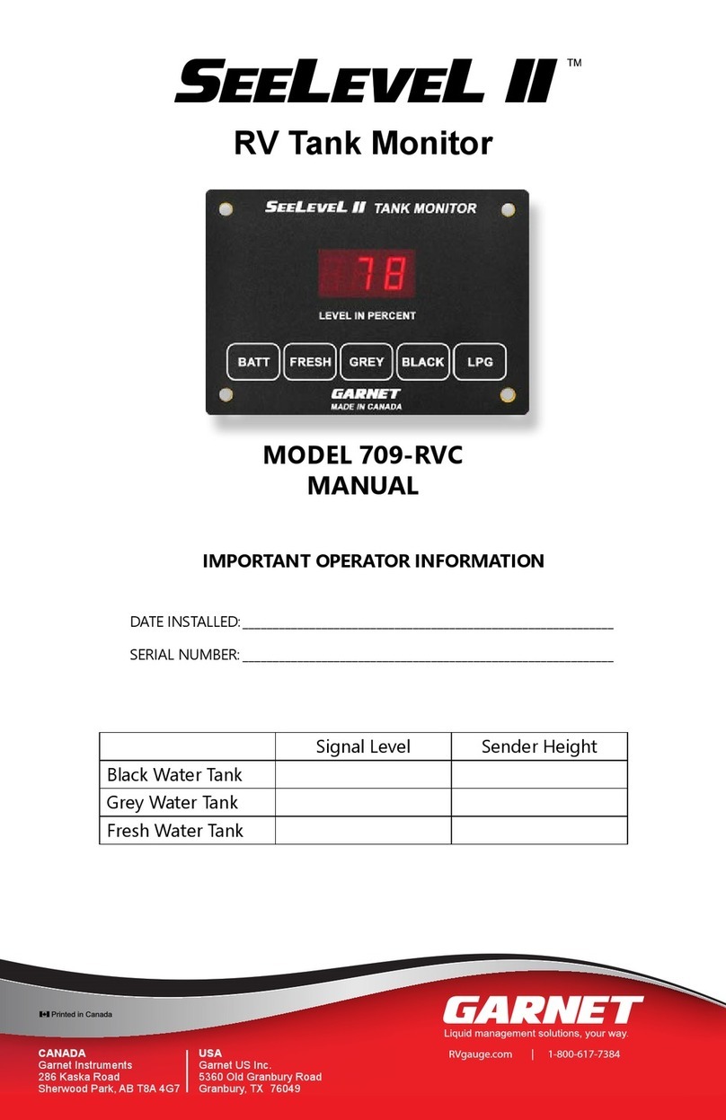
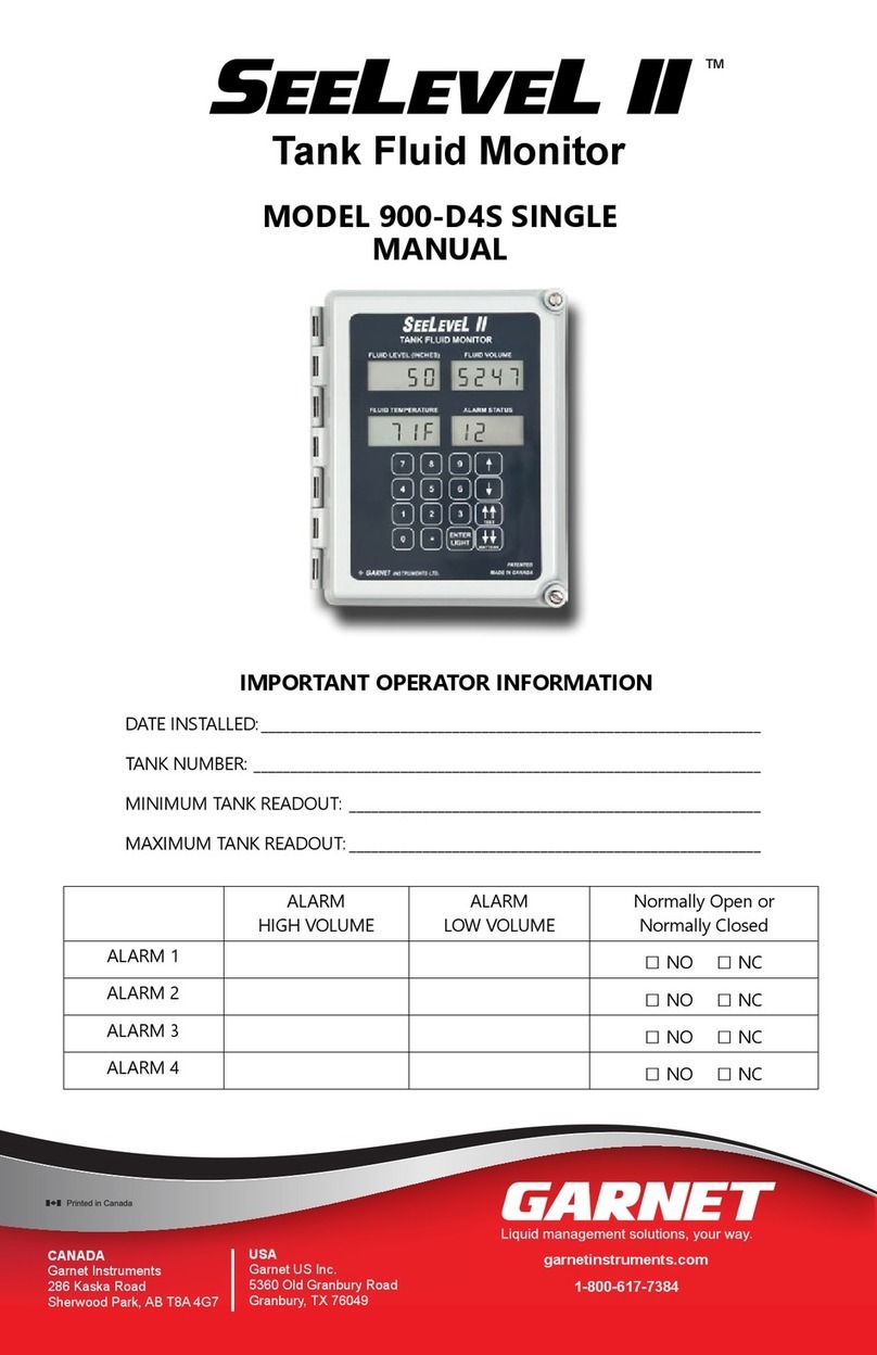
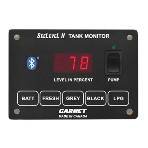
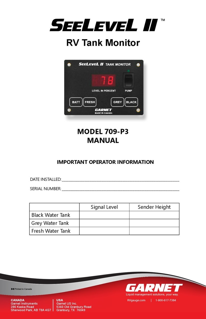
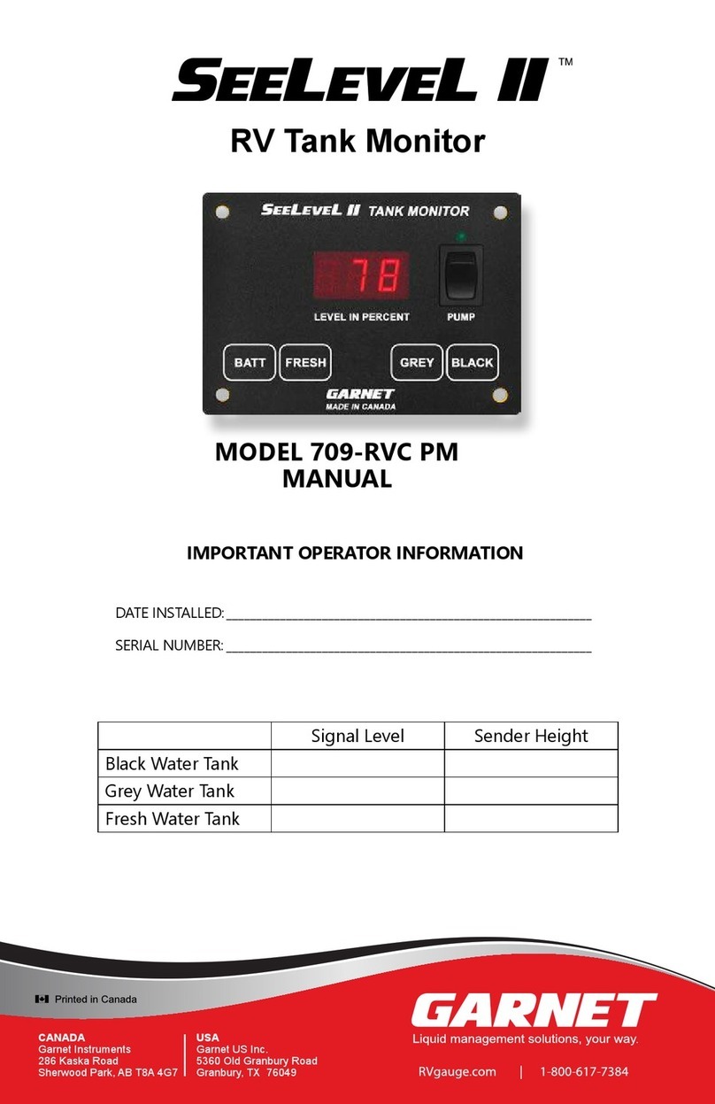
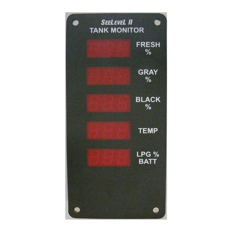
Garnet SeeLevel II User manual

USA
Garnet US Inc.
5360 Old Granbury Road
Granbury, TX 76049
CANADA
Garnet Instruments Ltd.
286 Kaska Road
Sherwood Park, AB T8A 4G7
garnetinstruments.com
1-800-617-7384
IMPORTANT OPERATOR INFORMATION
DATE INSTALLED:_____________________________________________________________
SERIAL NUMBER: _____________________________________________________________
SEELEVEL II TM
Holding Tank Monitor
709-N2K NLP / 709-N2KP NLP
MANUAL
PROTOTYPE

Page 2 709-N2K NLP/709-N2KP NLP Manual
Table of Contents
CHAPTER 1 - OVERVIEW.............................................................................................3
CHAPTER 2 - SYSTEM DESCRIPTION .....................................................................4
CHAPTER 3 - OPERATING INSTRUCTIONS ..........................................................6
CHAPTER 4 - DISPLAY CALIBRATION.....................................................................8
CHAPTER 5 - SENDER PROGRAMMING ............................................................. 12
CHAPTER 6 - INSTALLATION GUIDE..................................................................... 16
CHAPTER 7 - TROUBLESHOOTING GUIDE......................................................... 24
CHAPTER 8 - SPECIFICATIONS ............................................................................... 32
CHAPTER 9 - SERVICE AND WARRANTY INFORMATION............................ 33
MAIL IN WARRANTY ................................................................................................. 35
GARNET
SEELEVEL II TM
Tank Monitor
MODEL 709-N2K NLP / 709-N2KP NLP
709-N2K Manual_v3.0 - 28-May-2019
WCAUTION: explains safety information that could cause damage to the
product, including data loss.
WWARNING: explains dangers that might result in personal injury or death.
WNOTE: expands on information for any procedures.
SAFETY SYMBOLS INFORMATION
“Notes”, “Cautions”, and “Warnings” have been used throughout this manual to
bring special matters to the immediate attention of the reader.
PROTOTYPE

Page 3
709-N2K NLP/709-N2KP NLP Manual
The SEELEVEL II TM Tank Monitor represents a massive leap
forward in level measurement technology for the Recreational
Vehicle industry. The has a combination of features, accuracy,
reliability, and diagnostic capability that have never been available
before.
Garnet’s 709-N2K series models will monitor the battery voltage,
and the fresh water and sewer holding tanks. The information is
displayed on a 3-digit alpha-numeric LED display. The 709-N2KP
includes a pump switch. The 709-N2K series is also NMEA 2000
network compatible, the tank levels and capacity are available on the
NMEA bus for the fresh, grey, and black tanks. There is one alarm
output available which can be used to signal a high or low water
or sewer level as required. In addition, the system can display the
operating characteristics of each of the tank sending units, giving it
unsurpassed diagnostic capability.
CHAPTER 1 - OVERVIEW
W WARNING: All power circuits must be fused. If a fuse is not
provided with the system then it is the installer’s responsibility to install
a fuse with a maximum rating of 7.5 amps. A relay is required if more
than 7.5 amps is needed for the pump.
For more detailed information please refer to Chapter 7
“TROUBLESHOOTING GUIDE” and section “How to avoid damaging
the display or pump switch due to excessive current”.
PROTOTYPE

Page 4 709-N2K NLP/709-N2KP NLP Manual
CHAPTER 2 - SYSTEM DESCRIPTION
The SEELEVEL II TM consists of a display unit that mounts inside the RV,
and sender panels that stick to the side of the holding tank. A single
2 conductor wire is used to connect all the sender panels to the display.
adhered to the side of the holding tank. The sender panel can be cut to
length to match the height of the tank, and it auto-calibrates itself so that
it can read from empty to full regardless of the height of the tank. Three
ability to double-stack the senders to provide accurate level measurement
for tank heights ranging from 4 ½” to 34”.
710-ES
710-JS
Black water
holding tank LPG tank
Fresh water
holding tank
Grey water
holding tank
Three sender size options are available
to measure a variety of tank heights.
A second display
can be installed in
the service bay
with the holding
tanks.
The SEELEVEL II Tank Monitoring
system consists of a display unit
that mounts inside the RV.
Sender panels affix to
the outside of the
holding tank.
S
EE
L
EVE
LII
TANKMONITOR
BATT FRESH GREY BLACK LPG
S
EE
L
EVE
L II
TANK MONITOR
BATT FRESH GREY BLACK LPG
S
EE
L
EVE
L II
TANK MONITOR
BATT FRESH GREY BLACK LPG
The SEELEVEL II RV Tank Monitoring System
SS
710-SS
The Sender
The display receives the information from the three sender panels via a
single 2 conductor wire and shows the level information in percent of full
on a 3-digit LED display. When the button for a particular tank is pressed,
the display shows the level for that tank.
The Display
PROTOTYPE

Page 5
709-N2K NLP/709-N2KP NLP Manual
The vertical
transmit strip
sends out a radio
frequency signal.
Receiving segments
detect the dierence
between air and uid.
Level is calculated by the
system’s microprocessor.
The monitor displays the
tank level in percent full, on
a large 3-digit LED display.
Senders are installed on
the outside of the tank
using high strength
adhesive. They are never
fouled by sewage.
A large signal indicates the
segment is covered by water.
A small signal indicates the
segment is in air.
A medium signal indicates the
segment is partially covered by water.
The 710ES sender is accurate to 3/8” (1 cm)
SEELEVEL II TANK MONITOR
LEVEL IN PERCENT
BATT FRESH GREY BLACK LPG
4” (102 mm)
2.8” (71 mm)
Monitor depth varies
1” - 1 3/8” (25 - 35 mm)
model dependant.
The sender scans the water level through the tank wall using advanced
digital techniques programmed into the sender microprocessor. When
the sender transmits the water or sewer level information to the display,
it sends a digital code that has built-in error detection, making it highly
unlikely for the display to read an incorrect level, even if the wiring is
marginal.
In addition to the level, the sender also transmits diagnostic information
about its operation. This information can be used to determine if there is
buildup of sludge on the inside of the tank or to determine if the sender is
damaged or delaminating from the side of the tank. If sludge buildup in
the tank becomes extreme the gauge will cease to operate properly, so by
monitoring the signal power the tank can be cleaned before the buildup
gets excessive.
The system also shows the RV battery voltage by measuring the voltage
which powers the display. The voltage is shown with a resolution of 0.1
volt.
In order to keep the tank level and alarm information on the NMEA 2000
bus current, the display regularly scans the senders every 10-15 seconds.
When a tank button is pressed, the information displayed is recalled from
the most recent scan. A tank on hold is scanned more frequently. Systems
the scanning and the secondary display passively listens to the sender
information, this way both displays stay updated without interfering with
each other.
How it works
PROTOTYPE

Page 6 709-N2K NLP/709-N2KP NLP Manual
The display is the only system component that is accessed by the
user. All user input to the display is done using the four buttons
along the bottom of the display. Operation of the display is as follows:
To read a water or sewer tank level:
1. Press the button corresponding to the tank to be checked and
release it, the display will show the level in percent on the LED
display. If no other button is pressed, then the display will shut
2. BATT
to showing the new level or voltage. The 5-second timeout is
restarted every time a button is pressed.
3. To continuously display a reading, press and release the desired
button, and then press the same button a second time. When
the button is released, the display will be in hold mode, which
is indicated by the decimal point on the right-hand side turning
on. While the display is in the hold mode it will recheck the held
level every 2 - 3 seconds so the user can watch the level change
continue to be scanned every 10 - 15 seconds. The display will
hold mode before the 5 minutes is up, press any tank button,
To read the battery voltage:
1. Press the BATT button and release it, the display will show the
battery voltage on the LED display.
2. If no other button is pressed, then the display will shut down
after about 5 seconds. If the BATT button is held down, the
display will continuously recheck the voltage and show the
two values, for example, 12.6 and 12.7 volts. This is normal
behavior for a digital voltage display.
3. If another button is pressed before the 5-second time is up for
the BATT button, the display will immediately switch to showing
the value for the new button. The 5 second timeout is restarted
every time a button is pressed.
4. There is no hold mode for the battery voltage.
CHAPTER 3 - OPERATING INSTRUCTIONS
PROTOTYPE

Page 7
709-N2K NLP/709-N2KP NLP Manual
NMEA 2000 Bus Communication:
Instrument’s manufacturer code is 873, and the 709-N2K product
code is 15197. The 709-N2K adheres to NMEA database version
2.200. By changing the FRESH/GREY/BLACK to zero senders, you are
disabling that sender’s updates over the NMEA bus as well.
W NOTE: Anyone that intends to connect to the NMEA 2000 bus
information on NMEA 2000 protocol go to: www.nmea.org.never need
to be changed.
PROTOTYPE

Page 8 709-N2K NLP/709-N2KP NLP Manual
CHAPTER 4 - DISPLAY CALIBRATION
Set display to be primary or secondary
Press and
Press BATT + FRESH
set. Display shows “scn”. Once in that mode, FRESH = primary
PriGREYSEcBATT to save and exit.
Display rmware revision/visual alarm cue
Press
• + 5 seconds = version/revision. Display shows “rx.y” where x.y is
r1.2”. Release both buttons
to exit.
• + 10 seconds = visual alarm cue. Display shows “cuE”. Release
both buttons to edit. Options are either “on” or “oFF”. If set
to on, the visual alarm cue will be the 3rd decimal point on the
display. It will remain lit if any tank is in alarm status, even if the
FRESHBATT saves new setting
and exits. If the currently displayed tank is in alarm status, the
3rd LED will slowly blink while that tank is being displayed.
Set LED brightness
Press
• + 5 seconds = brightness menu. Display shows “bri”. Release
both buttons to edit. Allowable levels are “b-1
“b-5FRESH = dimmer, GREY = brighter. BATT to
save and exit.
Press
• + 5 seconds = primary/secondary indication. Display shows
either “Pri” or “SEc” depending on whether the display is set to
be a primary or a secondary. Release both buttons to exit.
BATT FRESH
BATT GREY
BATT BLACK
BATT FRESH
PROTOTYPE

Page 9
709-N2K NLP/709-N2KP NLP Manual
FRESH Tank Menus
Press
Set diagnostic option (no delay)
•
diA” displayed. Release either button to enter this
mode. After this mode is entered, the sensor’s relative power
Pxx” displayed, for example
“P58
be displayed for the next 5 seconds. “Hyy” displayed, for example
“H12”. Display clears when this mode exits.
Set alarm option (+5 seconds)
• Alarm option displayed for the next 5 seconds. “ALr” displayed.
Release either button to enter alarm simulation mode. Press
BATT to exit.
Alarm simulator
Display will initially be either “FHi” or “FLo”. This simulates
FRESH toggles high
<-> low. Press and hold FRESH for 3 seconds to enter the
alarm edit mode. Display will change to “FAS” = fresh alarm
set. Press BATT to exit.
Edit alarm level
The display will change to, for example, “L20.”. L = low alarm
triggers when tank level falls below the set value, which in
this case is 20%. H = high alarm triggers when tank level
rises above the set value. If the 1st decimal point is on, for
example “L.20”, that means “treat a failed sensor as 100%
full”. If the 1st decimal point is not on, that means “treat a
on, that means that alarm conditions on this tank will also
- Press and hold BLACK and the display will cycle through
“Lon”, “Loi”, “Hin”, and “Hii” with each press. “Lo”
= low alarm, “Hi” = high alarm. The 3rd letter means
either “n” for not included in the common alarm or “i”
for included in the common alarm.
- GREY
FRESH
- BATT to store settings and exit back to the alarm
simulation mode. “Sto FLo”
or “FHi”.
BATTFRESH
PROTOTYPE

Page 10 709-N2K NLP/709-N2KP NLP Manual
Edit connected senders (+10 seconds)
• Number of senders edit mode is displayed for next 5 seconds.
Display shows “FrS”. Release either button to enter the number
SE0”, “SE1”, or “SE2”. Press FRESH to cycle
through. BATT to save and exit.
Set tank capacity (+15 seconds)
• Tank capacity edit mode is displayed thereafter. “FcA” is
tank capacity edit mode. The unit will display the tank’s capacity,
in US gallons. Press FRESH to decrease and GREY to increase.
Press and hold either button to go fast. BATT to store and exit.
Follow the same steps for GREY and BLACK menus except for the
following:
GREY Tank Menus
Press
• Same structure as for fresh tank. Instead of “F” above, “g” will
be displayed.
BLACK Tank Menus
Press
• Same structure as for fresh tank. Instead of “F” above, “b” will
be displayed.
BATT
GREY
BATT
BLACK
PROTOTYPE

Page 11
709-N2K NLP/709-N2KP NLP Manual
Continuous display mode
Press FRESHFRESH
Press GREYGREY
Press BLACKBLACK
• Enables rapid tank read mode. Normal scan of a tank happens
approximately every 10 seconds. In continuous display mode,
the selected tank is scanned approximately every 2.5 seconds.
Times out after 10 minutes or until any button is pressed. 3rd
decimal point remains lit to indicate continuous tank display
mode is active. If the tank is in alarm status and the visual cue
option has been turned on, the 3rd decimal point will slowly
blink.
W NOTE: If there are any errors during setup go to the
“TROUBLESHOOTING GUIDE” chapter for display error codes.
PROTOTYPE

Page 12 709-N2K NLP/709-N2KP NLP Manual
CHAPTER 5 - SENDER PROGRAMMING
To program the 710ES or 710SS sender for the correct tank:
1. Since the senders are all connected in parallel to save wiring and
to simplify installation, the senders must be programmed so they
know which tank they are on. The senders can be programmed
for either the fresh, grey, or black tank. This is done with the
two tabs on the top corners of the sender. See the following
diagram.
2. The senders default to fresh tank operation if the programming
is not altered. Consequently, if the sender is for the fresh tank,
nothing further needs to be done to it.
3. If the sender is for the grey tank, remove the tab that says “GRY”
next to it.
4. If the sender is for the black tank, remove the tab that says “BLK”
next to it.
5. This is all that is required to program the senders for the correct
tank. However, if you make an error, you have one chance to
correct it, as described below.
6. If the “GRY” tab has been removed and it should be a black tank
sender, or if the “BLK” tab has been removed and it should be a
grey tank sender, then cut out the recessed grey-black correction
tab that says “GBC
and black tabs.
7. If either the “GRY” or “BLK” tabs have been removed and it
should be for a fresh tank, then remove the other “GRY” or “BLK”
tab. When both the “GRY” and “BLK” tabs are removed, it is
equivalent to neither of them being removed.
8. If the sender is single, no further programming is required.
9. If double stacked senders are used, the top sender must have
additional programming, as described below.
10. Refer to the 710ES and 710SS sender programming diagram.
To program the 710ES or 710SS sender as top or bottom:
1. Since the senders are all connected in parallel to save wiring
and to simplify installation, the senders must be programmed
so they know whether they are a single, top, or bottom sender.
This is done with the tab at the top center of the sender. See the
following diagram.
PROTOTYPE

Page 13
709-N2K NLP/709-N2KP NLP Manual
2. The senders default to single or bottom operation if the
programming is not altered. Consequently, if the sender is for
single or bottom operation, nothing further needs to be done to
3. For a top sender, remove the tab that says “TOP” next to it.
4. This is all that is required to program the senders for single, top,
or bottom use. However, if you make an error, you have one
chance to correct it, as described below.
5. If the “TOP” tab has been removed and it should be a single or
bottom sender, then cut out the recessed top correction tab that
says “TC
6. Verify that both the top and bottom senders have been
programmed for the correct tank.
To program the 710JS sender for the correct tank:
1. Since the senders are all connected in parallel to save wiring and
to simplify installation, the senders must be programmed so they
know which tank they are on. The senders can be programmed
for either the fresh, grey, or black tank. This is done with the
two tabs on the top corners of the sender. See the following
diagram.
2. The senders default to fresh tank operation if the programming
is not altered. Consequently, if the sender is for the fresh tank,
nothing further needs to be done to it.
3. If the sender is for the grey tank, remove the tab that says “GRY”
next to it.
4. If the sender is for the black tank, remove the tab that says “BLK”
next to it.
5. This is all that is required to program the senders for the correct
tank. However, if you make an error, you have one chance to
correct it, as described below.
6. If the “GRY” or “BLK” tab has been removed by mistake, the
sender can be changed to a fresh tank sender by cutting the
BLK” or “GRY
7.
PROTOTYPE

Page 14 709-N2K NLP/709-N2KP NLP Manual
710ES AND 710SS SENDER PROGRAMMING
PROTOTYPE

Page 15
709-N2K NLP/709-N2KP NLP Manual
710JS SENDER PROGRAMMING
PROTOTYPE

Page 16 709-N2K NLP/709-N2KP NLP Manual
Wire Colours on Connector
Wire Color Function
White 18 gauge Pump LED
Red 18 gauge +12V
Black 18 gauge Ground
Blue 18 gauge Tank Senders
Orange 18 gauge Common Alarm Output
CHAPTER 6 - INSTALLATION GUIDE
1. Please refer to the “Troubleshooting and Installation Tips”
section in Chapter 7 for details on avoiding installation issues.
2. The installation consists of mounting the display inside the RV,
cutting and fastening the senders to the sides of the holding
tanks, connecting wiring, and programming the display. When
wiring DO NOT use spade connectors to join wires, only use
crimp on butt connectors or solder the wires together.
3. Mount the display by cutting a hole in the wall 3” wide by 1 ⁄”
high and bringing the wiring out through the hole to connect to
the display panel connector.
4. Connect the wiring according to the following table. It is easier
plug the connector into the display panel. The senders need
to be grounded to a single ground wire from the display. Make
sure that the system ground is connected to the breaker panel
ground.
5. Determine where to mount the senders on the tanks. They will
the whole width of the sender is in contact with the side of the
tank, all the way from the top to the bottom of the tank. Make
sure that any metal is at least 1” away from either side or the top
and bottom of the sender, and at least 2” away from the face of
the sender. Clean the area well so that there is no dust, grease,
oil, water, etc., that would prevent the adhesive on the sender
from sticking.
6. Measure the height of the tank to determine which sender
to the following table.
W CAUTION: DO NOT mix sender types when stacking senders.
PROTOTYPE

Page 17
709-N2K NLP/709-N2KP NLP Manual
Tank
Height
Sender Options
Best Resolution Other Acceptable
4½” - 5” -
5” - 7” ES
7” - 13” ES SS
13” - 17” stacked ES SS
17” - 25” stacked ES stacked SS
25” - 34” stacked SS -
For single sender applications:
The sender ends should be ¼” to ½” away from the top and bottom
of the tank, to allow for the thickness of the tank top and bottom
to account for this distance from the bottom of the tank. The SS
sender is cut to the nearest even 2” in length. The ES sender is cut
to the nearest even 1.5” in length, for example, for a system with a
tank height of 11.75”, cut the sender to be 10.5” long, this allows ⁄”
at each end when the sender is centered vertically on the tank. The
For double stacked sender applications:
For tall tanks, double stacked 710ES or 710SS senders are used. The
sender ends should be ¼” to ¾” away from the top and bottom of
the tank, to allow for the thickness of the tank top and bottom and
account for this distance from the bottom of the tank. In addition,
there needs to be a gap of ⁄” to ⁄” in between the double senders.
Therefore the total length of both senders will be: tank height -¼”-
¼”-⁄
same length for best results. For example, if the tank height is 22”,
then 22”-¼”-¼”-⁄”= 21 ⁄”, so the total length of both ES senders
will be 21”. Make both senders 10.5” long.
WCAUTION: DO NOT cut the 710SS sender shorter than 6”. This
sender will not work if it is cut shorter than 6”. DO NOT cut the 710ES
sender shorter than 4 1/2”. This sender will not work if it is cut less than
not work if it is cut less than 4”.
PROTOTYPE

Page 18 709-N2K NLP/709-N2KP NLP Manual
710ES AND 710SS SENDER
PROTOTYPE

Page 19
709-N2K NLP/709-N2KP NLP Manual
710JS SENDER
PROTOTYPE

Page 20 709-N2K NLP/709-N2KP NLP Manual
7.
be cut is the bottom end, which is the opposite end from the top
8. The senders need to be programmed so they know which tank
on the top of the sender. See the chapter entitled “SENDER
PROGRAMMING” for details.
9. For double stacked sender systems, the senders also need to
be programmed so they know whether they are being used
as top or bottom senders. See the chapter entitled “SENDER
PROGRAMMING” for details.
10. Once the sender is cut to length and programmed, do a test
by taping the sender to the tank wall. Make sure there are no
air gaps between the sender and the tank. Verify operation
before permanently sticking the sender to the tank wall. Once
paper from ripping. Be careful not to bend the sender sharply
in the process. Position the sender over the side of the tank and
carefully stick it down.
Position the bottom of the sender at least ¼” above the bottom
of the tank, or slightly higher if required to equalize the space
at the top and bottom of the tank. Make sure that the sender is
square with the tank. You only have one shot at this, if you try to
by the sharp bending. Carefully press the sender down to the
tank so that all of the adhesive is contacting the tank wall.
11. Do steps 5 to 10 for the other two holding tanks.
12. Connect all the blue wires from the senders together, and to the
blue wire from the display. Connect the black wire from each
sender to ground at the display. It is very important that the
display and the senders have the same ground. Use crimp on
butt connectors to fasten the wires together.
WCAUTION: DO NOT cut the sides, and DO NOT cut the 710ES
sender shorter than 4 ½”. The cut must be in between the sensor
pads, and the cut must be made parallel to the existing bottom
end. Double check your measurements, if the sender is cut too
short, it cannot be lengthened.
W CAUTION: Make sure that the end with wires is pointing up!!
PROTOTYPE
Other manuals for SeeLevel II
2
This manual suits for next models
2
Table of contents
Other Garnet Measuring Instrument manuals

Garnet
Garnet SeeLeveL II 709-RVC PM User manual

Garnet
Garnet SEELEVEL II 714 User manual

Garnet
Garnet 900D6 DUAL User manual

Garnet
Garnet SeeLeveL Special 809-DM User manual

Garnet
Garnet Seelevel Special 808P2 Operating manual

Garnet
Garnet 709-RVC NLP User manual

Garnet
Garnet PC-732G User manual

Garnet
Garnet SeeLevel I 705 Series User manual

Garnet
Garnet SeeLeveL II 709-P3 User manual

Garnet
Garnet SeeLevel II 900-D4S Single User manual