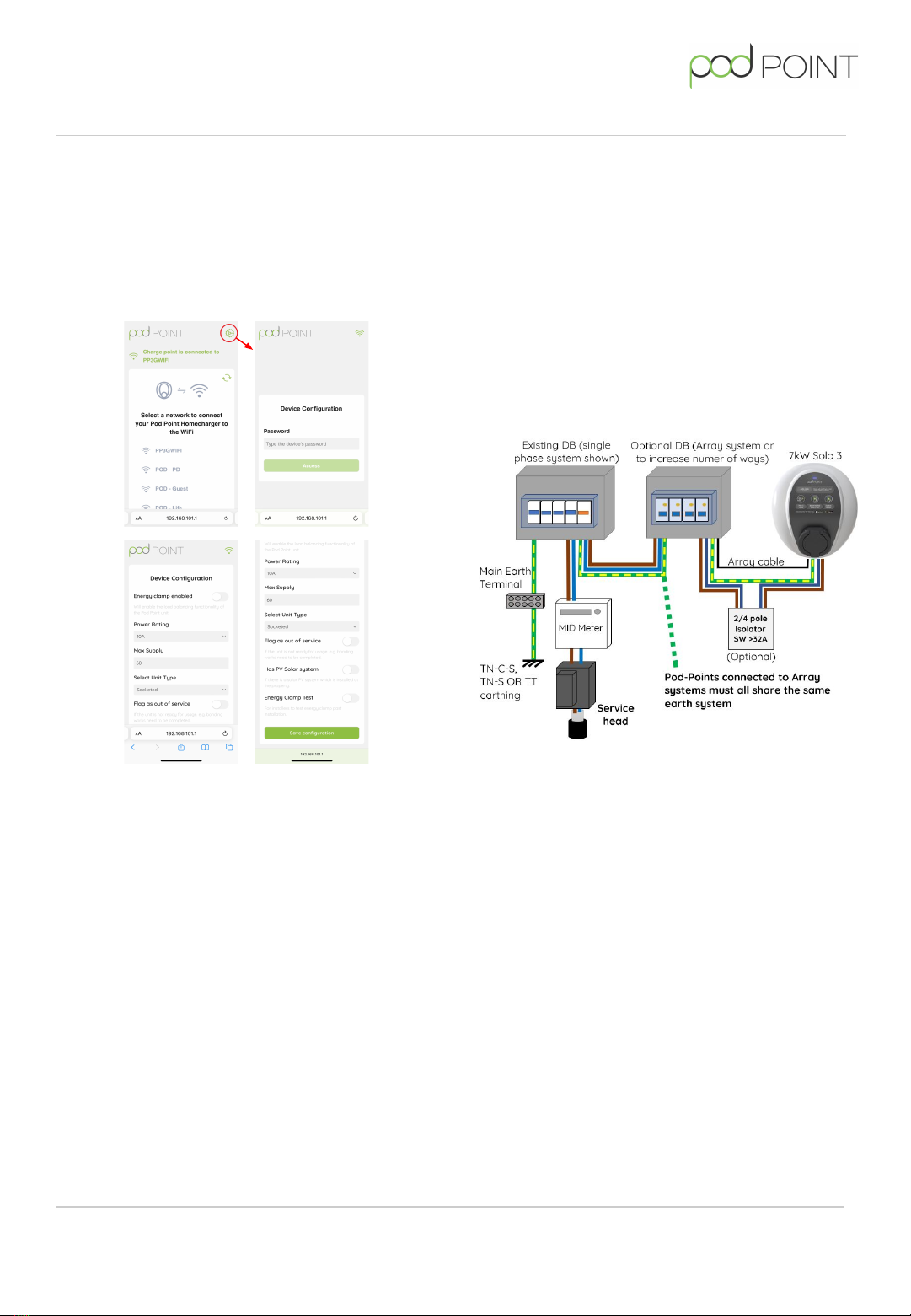
Pairing the Solo 3 to a Wi-Fi network
Detailed Solo 3 connection guide can be found
pod-point.com/technical/installation
On power up of the Solo 3 the front LED should
illuminate white. To connect the Solo 3 to a Wi-Fi
network do the following:
●Search for “podpoint” Wi-Fi network on your
mobile device and connect to it.
●On the device’s web browsers address bar
type: 192.168.101.1 then “Enter” or “OK”.
●A page displaying available networks will
show. Select the desired network and enter
the network password. Press “Connect” at the
bottom of the page.
Note:
The page will remain displayed but inactive after
“Connect” has been pressed.
●Wait for 1 minute. The LED should change to
blue with a short pink flash when it has
connected.
●If the status LED remains white, you may need
to restart the charger again and verify the
settings (see notes at end of this guide).
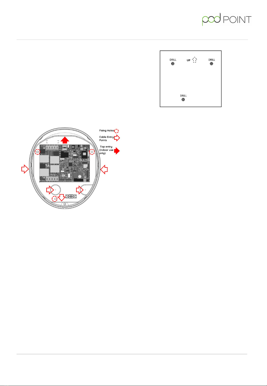
Fitting the front of the charger
Once the wiring, testing and setup of the Solo 3 is
completed, the front cover can be fitted in place.
Prior to fitting the front cover, visually check the
internal wiring will not interfere with assembly.
Dress if needed and remove any debris that may
have entered during installation.
Check that the front cover mating seal is in place
before fitting the cover to the housing. The front
cover can then be secured in place using the 6
screws.
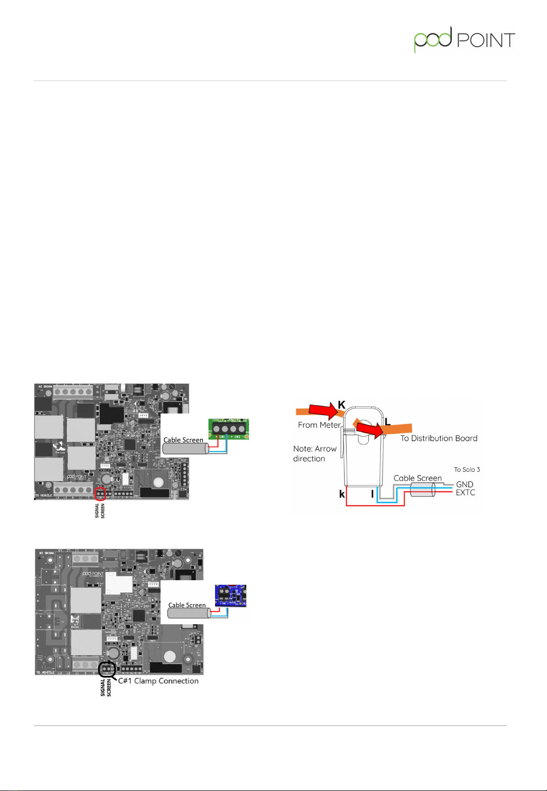
Remote diagnostics
When connected to the internet via Wi-Fi the
charger will provide information on supply
voltage(s), status of the incoming earth,
charging current, temperature, rating of
connected cable, etc. This data is primarily used
for internal diagnostic purposes but is also used
for energy usage displayed in the Pod Point App.
In exceptional circumstances Pod Point may
contact the site/charger owner if an abnormality
is detected.
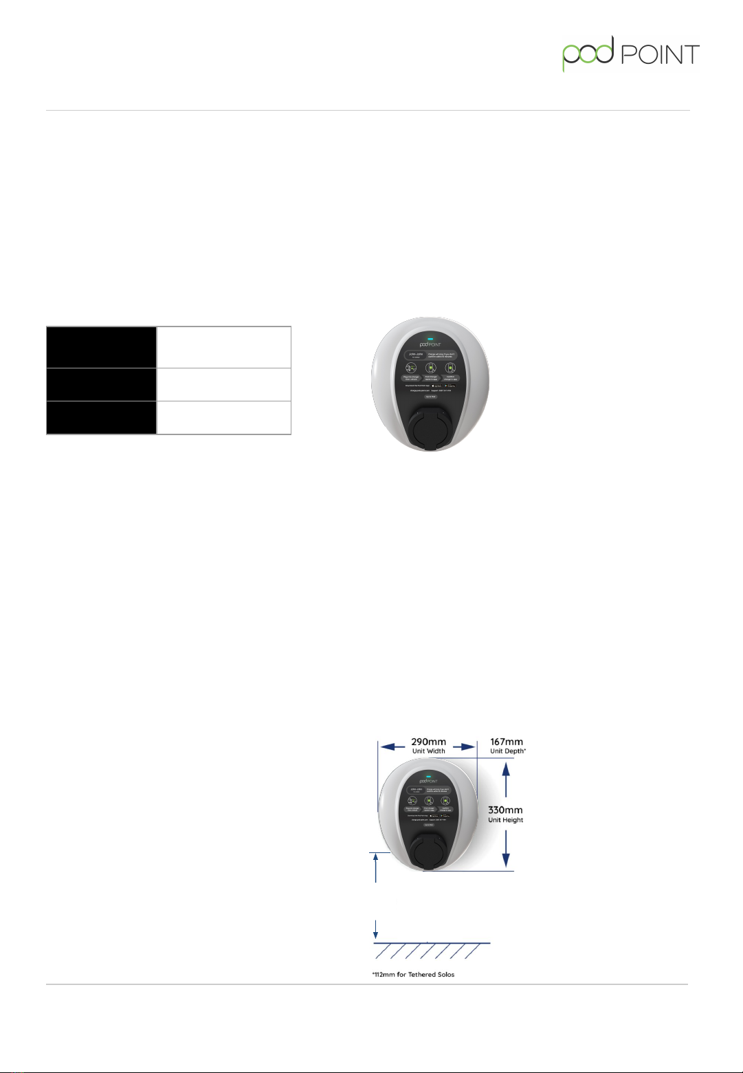
Solo 3 - Commercial
Solo 3 - Commercial PP-D-210451-3
Install Guide (No Dip Switches)
Theft of the Pod Point Solo 3
All Solo 3 EVSE includes a unique MAC address
to identify itself which is programmed into the
silicon and cannot be changed. If a Solo 3 is
reported as stolen and connection to the Pod
Point Network is attempted, it can be placed
permanently out of service.
Array configured Pod Point chargers do not
work as standalone units.
Additional product documents
We host our technical documentation across
two pages via pod-point.com
Technical documents
Installation documents
Or scan the QR code
here to get to our installer
documents page
Wi-Fi security
If a “guest” network can be setup on the router
(some ISP provided routers do not have this
feature), limiting connection to one device with
access limited only to the internet gives security
conscious users some peace of mind.
Setting up an allowlist on a router adds an
additional layer of security from attackers. This
requires some level of IT knowledge to add the
various MAC addresses. It also makes the
connection of any future devices more dicult.
Using the Wi-Fi router's SSID and password will
not automatically allow connection.
Viewing a router’s list of connected devices
should reveal the Solo 3 as “podpoint” followed
by a number (MAC address). This MAC address
may be used for the setting up of an allowlist.
WPS and PIN number access are regarded as
insecure and should be disabled in the router
settings if not used.