EFD ULTIMUS V User manual

www.efd-inc.com [email protected] USA & Canada 800.556.3484 Europe +44 (0) 1582 666334 Asia & China: +86 (21) 3866 9006
Sales and service of EFD®dispensing systems are available worldwide.
™
®
A NORDSON COMPANY
U
LTIMUS
™
V
High Precision Dispenser
Electronic pdf files of EFD manuals are
also available at www.efd-inc.com
User’s Guide

You have selected a reliable, high quality Ultimus dispensing system from EFD, the world leader in
fluid dispensing.The Ultimus dispensing system was designed specifically for industrial dispensing,
and will provide you with years of trouble-free, productive service.
This User’s Guide will help you maximize the usefulness of your Ultimus dispensing system.
Please spend a few minutes to become familiar with the controls and features. Follow our
recommended testing procedures. Review the helpful information we have included, which is based
on more than 30 years of industrial dispensing experience.
Most questions you will have are answered in this guide. However,if you need assistance, please do
not hesitate to contact EFD or your authorized EFD distributor.
In the USA, call 800.556.3484 between 8:30 a.m. and 5:30 p.m. Eastern time.
In Europe, call +44 (0) 1582 666334.
In Asia, call +86 (21) 3866 9006.
In all other areas, call your authorized EFD distributor or +1.401.431.7000.
The EFD Pledge
Thank You!
You have just purchased the world’s finest dispensing equipment.
I want you to know that all of us at EFD value your business and will do everything in our power to
make you a satisfied customer.
If at any time you are not fully satisfied with our equipment or the support provided by your EFD
Product Application Specialist, please contact me personally at 800.556.3484 (US),
I guarantee that we will resolve any problems to your satisfaction.
Thanks again for choosing EFD.
Peter Lambert, President
Introduction
www.efd-inc.com [email protected] USA & Canada 800.556.3484 Europe +44 (0) 1582 666334 Asia & China: +86 (21) 3866 9006
Sales and service of EFD®dispensing systems are available worldwide.
Peter Lambert
2

Product Safety Statement . . . . . . . . . . . . . . . . . . . . . . . . . . . . . . . . . . . . . . . . . . . . . . . . 4
Specifications. . . . . . . . . . . . . . . . . . . . . . . . . . . . . . . . . . . . . . . . . . . . . . . . . . . . . . . . . 8
Features. . . . . . . . . . . . . . . . . . . . . . . . . . . . . . . . . . . . . . . . . . . . . . . . . . . . . . . . . . . . . 9
Unpacking the Dispenser . . . . . . . . . . . . . . . . . . . . . . . . . . . . . . . . . . . . . . . . . . . . . . . 10
Features and Controls . . . . . . . . . . . . . . . . . . . . . . . . . . . . . . . . . . . . . . . . . . . . . . . . . .11
Initial Setup for Testing . . . . . . . . . . . . . . . . . . . . . . . . . . . . . . . . . . . . . . . . . . . . . . . . 13
Dispensing System Setup . . . . . . . . . . . . . . . . . . . . . . . . . . . . . . . . . . . . . . . . . . . . . . . 14
Initial Settings. . . . . . . . . . . . . . . . . . . . . . . . . . . . . . . . . . . . . . . . . . . . . . . . . . . . . . . . 17
Basic Menu Operation . . . . . . . . . . . . . . . . . . . . . . . . . . . . . . . . . . . . . . . . . . . . . . . . . 18
Setting Dispense Time, Pressure and Vacuum . . . . . . . . . . . . . . . . . . . . . . . . . . . . . . . . 24
Dispense Modes. . . . . . . . . . . . . . . . . . . . . . . . . . . . . . . . . . . . . . . . . . . . . . . . . . . . . . 24
Using Auto Increment Mode . . . . . . . . . . . . . . . . . . . . . . . . . . . . . . . . . . . . . . . . . . . . . 26
Sample Memory Cell Settings . . . . . . . . . . . . . . . . . . . . . . . . . . . . . . . . . . . . . . . . . . . . 28
Appendix A I/O Connector Pin Descriptions . . . . . . . . . . . . . . . . . . . . . . . . . . . . . . . . . 29
Appendix B RS-232 Connection Protocol. . . . . . . . . . . . . . . . . . . . . . . . . . . . . . . . . . . 33
Replacement Parts . . . . . . . . . . . . . . . . . . . . . . . . . . . . . . . . . . . . . . . . . . . . . . . . . . . . 46
Notes. . . . . . . . . . . . . . . . . . . . . . . . . . . . . . . . . . . . . . . . . . . . . . . . . . . . . . . . . . . . . . 49
Warranty. . . . . . . . . . . . . . . . . . . . . . . . . . . . . . . . . . . . . . . . . . . . . . . . . . . . . Back Cover
Contents
www.efd-inc.com [email protected] USA & Canada 800.556.3484 Europe +44 (0) 1582 666334 Asia & China: +86 (21) 3866 9006
Sales and service of EFD®dispensing systems are available worldwide.
3
4
EFD PRODUCT SAFETY STATEMENT
This statement provides personal and equipment safety notices for EFD dispensing products excluding
the TT dispensing robot. For the safety statement on the TT dispensing robot, please see the TT
user’s guide.
The safety message that follows has a WARNING level hazard.
Failure to comply could result in death or serious injury.
ELECTRIC SHOCK
Risk of electric shock. Disconnect power before removing cover and/or disconnect,
lock out, and tag switches before servicing electrical equipment. If you receive
even a slight electrical shock, shut down all equipment immediately. Do not
restart the equipment until the problem has been identified and corrected.
The safety messages that follow have CAUTION level hazards.
Failure to comply may result in minor or moderate injury.
READ MANUAL
Read manual for proper use of this equipment. Follow all safety instructions. Task-
and equipment-specific warnings,cautions and instructions are included in equipment
documentation where appropriate. Make sure these instructions and all other
equipment documents are accessible to persons operating or servicing equipment.
MAXIMUM AIR PRESSURE
Maximum air input pressure 100 psi (6.9 bar). Excessive air input pressure
may damage the equipment.
BURST PRESSURE
Maximum air input pressure 100 psi (6.9 bar). Burst pressure 300 psi (20.7 bar).
Excessive air input pressure may damage the equipment.
RELEASE PRESSURE
Release pressure before opening. Maximum pressure 30 psi (2.0 bar). Release
hydraulic and pneumatic pressure before adjusting or servicing pressurized
systems or components.
CAUTION
WARNING
EFD
Product
Safety
Statement
www.efd-inc.com [email protected] USA & Canada 800.556.3484 Europe +44 (0) 1582 666334 Asia & China: +86 (21) 3866 9006
Sales and service of EFD®dispensing systems are available worldwide.

5
Halogenated Hydrocarbon Solvent Hazards
Do not use halogenated hydrocarbon solvents in a pressurized system that contains aluminum components.
Under pressure, these solvents can react with aluminum and explode, causing injury, death,or property
damage. Halogenated hydrocarbon solvents contain one or more of the following elements:
Element Symbol Prefix
Fluorine F “Fluoro-”
Chlorine Cl “Chloro-”
Bromine Br “Bromo-”
Iodine I “Iodo-”
Check your material MSDS or contact your material supplier for more information. If you must use
halogenated hydrocarbon solvents, contact your EFD representative for compatible EFD components.
High Pressure Fluids
High pressure fluids, unless they are safety contained, are extremely hazardous.Always release fluid
pressure before adjusting or servicing high pressure equipment.A jet of high pressure fluid can cut like
a knife and cause serious bodily injury, amputation, or death.Fluids penetrating the skin can also cause
toxic poisoning.
Warning: Any injury caused by high pressure liquid can be serious. If you are injured or even suspect
an injury:
• Go to an emergency room immediately.
• Tell the doctor that you suspect an injection injury.
• Show the doctor this note.
• Tell the doctor what kind of material you were dispensing.
Medical Alert–Airless Spray Wounds: Note to Physician
Injection in the skin is a serious traumatic injury. It is important to treat the injury surgically as soon as
possible. Do not delay treatment to research toxicity.Toxicity is a concern with some exotic coatings
injected directly into the bloodstream.
Qualified Personnel
Equipment owners are responsible for making sure that EFD equipment is installed, operated and serviced
by qualified personnel. Qualified personnel are those employees or contractors who are trained to safely
perform their assigned tasks.They are familiar with all relevant safety rules and regulations and are
physically capable of performing their assigned tasks.
EFD
Product
Safety
Statement
www.efd-inc.com [email protected] USA & Canada 800.556.3484 Europe +44 (0) 1582 666334 Asia & China: +86 (21) 3866 9006
Sales and service of EFD®dispensing systems are available worldwide.

www.efd-inc.com [email protected] USA & Canada 800.556.3484 Europe +44 (0) 1582 666334 Asia & China: +86 (21) 3866 9006
Sales and service of EFD®dispensing systems are available worldwide.
6
Intended Use
Use of EFD equipment in ways other than those described in the documentation supplied with the
equipment may result in injury to persons or damage to property. Some examples of unintended use
of equipment include:
• Using incompatible materials
• Making unauthorized modifications
• Removing or bypassing safety guards or interlocks
• Using incompatible or damaged parts
• Using unapproved auxiliary equipment
• Operating equipment in excess of maximum ratings
• Operating equipment in an explosive atmosphere
Regulations and Approvals
Make sure all equipment is rated and approved for the environment in which it is used.Any approvals
obtained for EFD equipment will be voided if instructions for installation, operation and service are not
followed.
Personal Safety
To prevent injury, follow these instructions:
• Do not operate or service equipment unless you are qualified.
• Do not operate equipment unless safety guards, doors or covers are intact and automatic
interlocks are operating properly. Do not bypass or disarm any safety devices.
• Keep clear of moving equipment. Before adjusting or servicing moving equipment, shut off the
power supply and wait until the equipment comes to a complete stop. Lock out power and secure
the equipment to prevent unexpected movement.
• Make sure spray areas and other work areas are adequately ventilated.
• Know where emergency stop buttons, shutoff valves and fire extinguishers are located.
• Clean – Apply a small amount of light detergent onto a moist cloth and wipe surface of unit
lightly, cleaning any stains or spilled adhesive.
• Maintain – Only use clean dry air and regulated power supply to unit. Equipment does not require
any other regular maintenance.
• Test – Verify operation of features and performance of equipment using the appropriate sections
of this user guide.A faulty or defective unit should be returned to EFD or representative for
refurbishment.
• Use only replacement parts that are designed for use with original equipment.
Contact your EFD representative for information and advice.
• Caution: Use EFD filter/muffler (P/N 7016875) or wear adequate ear protection when operating
the vacuum in close proximity for a prolonged period of time.
EFD
Product
Safety
Statement

www.efd-inc.com [email protected] USA & Canada 800.556.3484 Europe +44 (0) 1582 666334 Asia & China: +86 (21) 3866 9006
Sales and service of EFD®dispensing systems are available worldwide.
7
Action in the Event of a Malfunction
If a system or any equipment in a system malfunctions, shut off the system immediately and perform the
following steps:
• Disconnect and lock out system electrical power. If using hydraulic and pneumatic shutoff valves,close
and relieve pressure.
• Identify the reason for the malfunction and correct it before restarting the system.
• For EFD air-powered dispensers, remove the syringe barrel from the adapter assembly. For EFD
electro-mechanical dispensers, slowly unscrew the barrel retainer and remove the barrel from the
actuator.
Disposal
Dispose of equipment and materials used in operation and servicing according to local codes.
EFD
Product
Safety
Statement
RoHS标准相关声明 (China RoHS Hazardous Material Declaration)
产品名称 有害物质及元素
Part Name Toxic or Hazardous Substances and Elements
铅 汞 镉 六价铬 多溴联苯 多溴联苯醚
Lead Mercury Cadmium Hexavalent Polybrominated Polybrominated
Chromium Biphenyls Diphenyl Ethers
(Pb) (Hg) (Cd) (Cr6) (PBB) (PBDE)
金属转接头 XO O O O O
All Brass Fittings
O: 表示该产品所含有的危险成分或有害物质含量依照EIP-A, EIP-B, EIP-C
的标准低于SJ/T11363-2006 限定要求。
O: Indicates that this toxic or hazardous substance contained in all the homogeneous materials for this part,
according to EIP-A, EIP-B, EIP-C is below the limit requirement in SJ/T11363-2006.
X: 表示该产品所含有的危险成分或有害物质含量依照EIP-A, EIP-B, EIP-C
的标准高于SJ/T11363-2006 限定要求.
X: Indicates that this toxic or hazardous substance contained in all the homogeneous materials for this part,
according to EIP-A, EIP-B, EIP-C is above the limit requirement in SJ/T11363-2006.
Important Safety Information
All EFD disposable components,including syringe barrels,cartridges,pistons,tip caps,end caps,and
dispense tips,are precision engineered for one-time use. Attempting to clean andre-usecomponents
will compromise dispensing accuracy and may increase the risk of personal injury.
Always wear appropriate protective equipment and clothing suitable for your dispensing application.
•
Do not exceed maximum operating pressure of 100 psi (7.0kg/cm2).
•
Do not heat syringe barrels or cartridges to a temperature greater than 100°F (38°C).
•
Dispose of components according to local regulations after one-time use.
•
Do not clean components with strong solvents (e.g. MEK,Acetone,THF).
• Cartridge retainer systems and barrel loaders should be cleaned with mild detergents only.
•
To prevent fluid waste, use EFD SmoothFlowTM pistons.

www.efd-inc.com [email protected] USA & Canada 800.556.3484 Europe +44 (0) 1582 666334 Asia & China: +86 (21) 3866 9006
Sales and service of EFD®dispensing systems are available worldwide.
8
Specifications
SPECIFICATIONS
Cabinet Dimensions: 95 mm (3.74 in) Hx 225 mm (10.04 in) Wx 199 mm (7.85 in) D
Weight: 3.36 kg (7 lb,6.5 oz) with feet
Input AC (to power supply): 100-240 VAC, 1.8 Amp, 47-63Hz
Output DC (from power supply): 24 VDC, 1.66 Amp maximum
Internal Voltage: 24 VDC
Footswitch: 24 VDC
Cycle Initiate: Foot Pedal, Finger Switch, I/O
Air Input Requirements: 15 psi (1.4 bar) minimum to 100 psi (6.9 bar) maximum
Air Output: 0-100 psi (0-6.9 bar)
Temperature: 5°C to 50°C (41°F to 122°F)
Humidity: 85%RH at 30°C noncondensing
Approvals: RoHS,WEEE & China RoHS Compliant, CE

www.efd-inc.com [email protected] USA & Canada 800.556.3484 Europe +44 (0) 1582 666334 Asia & China: +86 (21) 3866 9006
Sales and service of EFD®dispensing systems are available worldwide.
9
ULTIMUS V FEATURES
• Electronically change/adjust dispensing Time, Pressure and Vacuum
• Simultaneously display dispensing Time, Pressure and Vacuum
• Auto Increment mode to adjust dispensing parameters after a certain number of shots
or a specific lapsed time.
• Auto Sequence mode that allows deposit patterns to be repeated automatically.
• 400 individual memory storage cells
• Scroll or select cells via front panel keypad or external PC/PLC control
• Switching between Steady,Timed and Teach modes
• Front panel Manual Cycle key
• Teach function
• Multi-level operator lockout
• Alarm indicators
• End of Cycle Feedback loop
• Soft button data input 0-9 keypad
• Operator control of LCD display brightness
• Easy UP/DOWN arrow key navigation
• External PC interface for data input
• Display cycle counter
• RS-232 interface compatible with Standard RS-232 protocol
• ESD Safe via connection with external ESD grounding plug
• 0-100 psi (0-6.9 bar) air regulation range; 0-18 H O vacuum regulation range
• Internal universal power supply
• D-sub I/O (15-pin) and communication (9-pin) connections
• Alarm input/output I/O signals
ULTIMUS V
Features
2

Unpacking
The Dispenser
www.efd-inc.com [email protected] USA & Canada 800.556.3484 Europe +44 (0) 1582 666334 Asia & China: +86 (21) 3866 9006
Sales and service of EFD®dispensing systems are available worldwide.
The following items should be included with your Ultimus V dispenser:
1. Tubing-6mm OD Blue Urethane
2. Connector 15 Pos Plug D-Sub Solder
3. Backshell 15 Pos D-Sub
4. Hose Support Adapter
5. Filter Regulator
6. Power Cord,American Plug
7. Foot Pedal Assembly
8. Barrel Holder Sleeve
9. Barrel Holder
10. Ergonomic Barrel Holder
11. Hose Support Locating Washer
12. Fitting-1/4npt X 6mm OD
13. Wrench - Hex Key, 4mm
14. Screw - M6 X 25mm, Bh, Blk
(Not Shown)
Literature - Optimum Component Poster
Complaints Card
Dot Test Kit Sheet
Box of 50 tip caps
CD containing the User Manual and Ultimus V Interactive software
1
2
3
7
4
6
5
8
9
10
13
12
11
14
UNPACKING THE DISPENSER
Unpack the contents of the package and lay them out on a clean workbench.
10

Front Panel
Power Switch: Turns the Ultimus V dispenser on and off.
RS-232 Connector: Allows all dispensing parameters to be modified from a remote PC or PLC.
LCD Display: Shows data and system status as well the current function selected.
Function Buttons: Used to select items shown on the bottom of the LCD display above the individual
function buttons.The function of each key depends on the current screen display and/or mode.
Cycle Button: Initiates a dispense cycle.
Air Output Quick Connector: Syringe barrel adapter/Optimeter™ connection.
ESD Jack: Standard 0.166” banana jack allows the user to connect grounding for ESD-sensitive equipment.
Numeric Keypad: Used to enter settings.
Scroll Keys: The arrow-shaped 2,4,6 and 8 keys on the numeric keypad can be used for cursor scrolling as
well as data entry.
Easy Adjust Buttons: Adjusts dispense time or memory cell location.
Enter Key: Confirms highlighted selection or data entered.
Features &
Controls
Front Panel
Power Switch Function Buttons ESD Jack Enter Key
Easy Adjust
Buttons
RS-232
Connector
LCD Display
Air Output Quick
Connector
Cycle Button Numeric Keypad
Scroll Keys
FEATURES AND CONTROLS
11
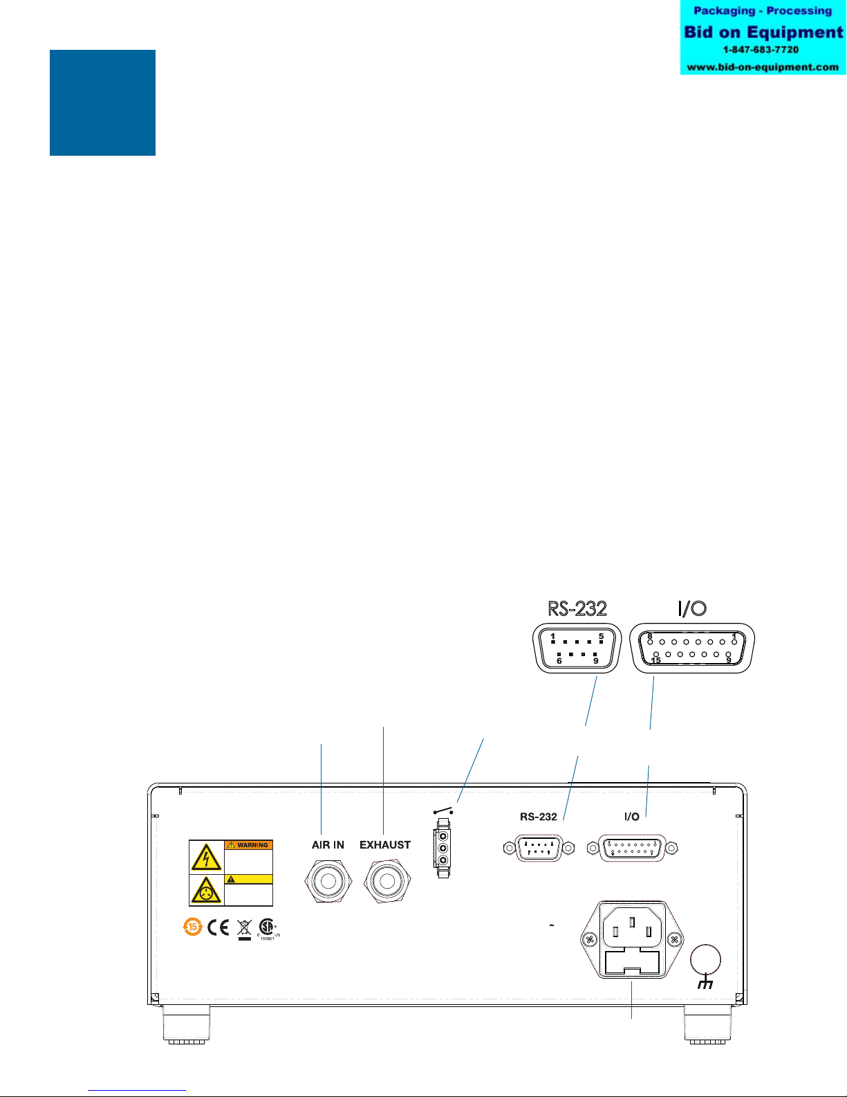
Back Panel
Air In: Main filtered air supply input.
6mm push-in fitting, used to connect main air supply. Minimum 15 psi (1.0 bar) above desired dispensing
pressure; maximum 100 psi (6.9 bar).
Exhaust: Syringe barrel and vacuum air exit port.
6 mm push-in fitting. Output air from the syringe barrel exits from this port at the end of every dispensing
cycle.The air consumed by the vacuum generator exhausts through this port as well.The push-in fitting
allows tubing to be connected for remote discharge.
Foot Pedal/Finger Switch Connector: Connection for dispenser actuating device.
Connection is for a momentary contact closure switching device. EFD strongly suggests the use of EFD
foot pedals and finger switches, which are specifically designed for this application.
RS-232 Connector: (DB-9 Male Style)
Either the front or rear RS-232 port can be enabled at one time. The RS-232 port is selected in the
Communication LCD screen.
Any communications to the disabled RS-232 port will be ignored by the dispenser. The RS-232 protocol
is covered in Appendix B.
I/O (Input/Output) Connector: (DB-15 Female Style) Used to connect to any input or output.
For detailed pin information, refer to AppendixA.
AC Power Input: Connects dispenser to local power source.
Features &
Controls
Back Panel
INPUT: 100-240 VAC 1.8A
47-63 Hz
FUSE: 1.0A 250V
5 X 20 MM
Risk of electric shock.
Disconnect power before
removingcover. Read
manual for proper use.
Max. air input pressure
100 psi (6.9bar). Refer
to manual.
CAUTION
Power Input Jack
Air In
Foot Pedal/Finger
Switch Connector
Exhaust
I/O (Input/Output)
Connector
RS-232
Connector
12

Connect Power
1. Connect the power cord to the back of the dispenser.
2. Plug the power cord into your local power source.
3. Turn the power switch on the front panel to the on position.
Connect Foot Pedal
The Ultimus V can be operated using the foot pedal provided, or by an external device via a
DB-15 connector.
1. Plug the foot pedal into the connector on the back of the dispenser.
2. You can also operate the Ultimus V with an optional finger switch or a 5 to 24VDC pulse.
Connect Air Input
Note: Clean, dry, filtered factory air is required to meet warranty.To ensure air quality,
install the five-micron filter regulator provided with the Ultimus V.
1. Push one end of the air input hose into the Air In fitting on the back of the dispenser.
2. Connect the other end of the air input hose to the filter regulator supplied with the
Ultimus V dispenser.
Note: Input air should be set at least 15 psi (1.0 bar) - or more - higher than dispensing
pressure, up to a maximum of 100 psi (6.9 bar).
Connect Air Output
Push the connector on the adapter/Optimeter™ into the connector on the front of the
Ultimus V and twist clockwise to lock.
Attach Syringe Barrel and Tip
1. Secure an EFD syringe barrel filled with your fluid to the adapter/Optimeter™.
2. Replace the tip cap with an appropriate EFD precision dispense tip.
Initial Setup
For Testing
www.efd-inc.com [email protected] USA & Canada 800.556.3484 Europe +44 (0) 1582 666334 Asia & China: +86 (21) 3866 9006
Sales and service of EFD®dispensing systems are available worldwide.
INITIAL SETUP FOR TESTING
13

www.efd-inc.com [email protected] USA & Canada 800.556.3484 Europe +44 (0) 1582 666334 Asia & China: +86 (21) 3866 9006
Sales and service of EFD®dispensing systems are available worldwide.
Dispensing
System
Setup
Deposit size is controlled by time, pressure and tip size.
Please follow these instructions to test each function. Use the convenient Dot Standards sheet included in
your dispensing kit.
Using Steady Mode to Dispense a Dot or Stripe or Fill a Cavity
1. Start with pressure set to zero.
2. Place the syringe barrel over a piece of paper or test surface.
3. Place the unit in “Steady” mode.
4. Unsnap the safety clip. Depress and hold the foot pedal for the remainder of setup.
5. While resting the tip on the paper (test surface), increase the air pressure by 1-2 psi (.069-.138 bar)
using the keypad until you have reached the desired fluid dispensing flow rate.
Note: Always use the lowest possible pressure and the largest possible tip size.The combination of the
lowest possible output pressure + largest possible tip size + longest possible dispense duration =
most consistent and accurate deposits.
6. Release the foot pedal.
7. Retest the dispensing rate a few more times. Fine tune as required by making small changes in
pressure.
Correct angle
for consistent
deposits.
Remember - always
bring the tip in contact
with the work surface at
the illustrated angle.
After the tip is in
position, press the foot
pedal. Release pedal
and remove tip by lifting
straight up.
DISPENSING SYSTEM SETUP
14

Dispensing
System
Setup
Using Timed Mode to Make Repeatable Deposits
1. Refer to the previous section to purge your dispense tip of air and fill it with fluid.
2. Place the unit into “Timed” mode.
3. Set the dispense time.The dispense time or duration may be set in one of two ways:
• Using the Up/Down Arrows to set time. Refer to the“
Features and Controls
” section.
• Using the Program/Teach button to set time. Refer to the “
Features and Controls
” section.
4. Press the foot pedal/finger switch to activate the dispense cycle.The dispenser will now continuously
dispense for the pre-set duration of time. Once the time has expired, the dispenser will stop dispensing
and await another triggering signal from the foot pedal/finger switch or signal from the host controller.
Note: The foot pedal/finger switch only needs to be pressed for a moment.
If the foot pedal/finger switch or contact closure I/O signal is initiated at any time during the dispense cycle,
the dispenser will immediately abort and stop dispensing.This is a unique safety feature to prevent
accidental dispensing.
Using the Vacuum Control Feature for Low Viscosity Fluids
The Vacuum Control feature allows you to dispense low viscosity fluids consistently without dripping
between cycles. The vacuum overcomes head pressure on the fluid within the barrel,
which prevents dripping.
1. Make sure that you have attached an EFD syringe barrel filled with the fluid
intended for dispensing, and that the air pressure is set all the way to zero. EFD
recommends the use of a Blue LV Barrier piston for watery, low viscosity materials.
2. Make sure the barrel adapter safety clip is closed.
3. Remove the tip cap and replace it with an appropriate EFD dispense tip.
4. Set the air pressure at 2 psi (0.1 bar)
5. While pointing the tip over a container or resting it on a test surface, release the
safety clip on the adapter/Optimeter™ hose assembly.
6. Place the dispenser in “Steady” mode.Depress and hold the foot pedal until a drip
begins to form at the end of the tip.
7. Release the foot pedal.At this point, fluid will continue to exit the tip.
8. Increase the vacuum using the keypad by 0.5 to 1.0 inches of water until the fluid
deposit size stabilizes without growing.
Note: Do not increase the vacuum to the point where the deposit is actually drawn back into the tip or to
where bubbles form in the barrel. Excessive vacuum causes inconsistent dispensing.
9. Lift the tip off the test surface, wipe the tip end and retest by pressing the foot pedal momentarily.
The deposit should stay at the intended size and not increase or decrease in size. If it does, repeat
steps 4-8 to fine-tune the vacuum control.
10. Once vacuum is properly set increase air pressure to the desired production setting before beginning
your dispensing process.
15
LV Barrier
1/2 maximum fill
Air gap
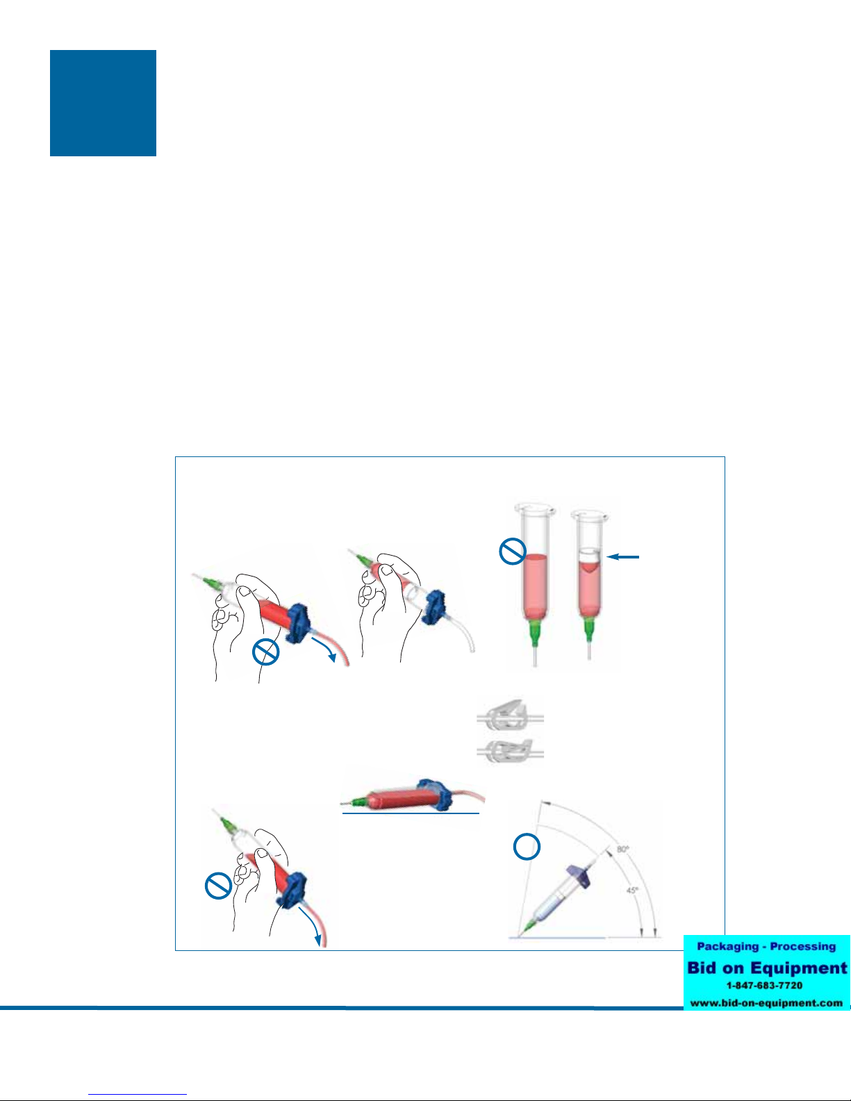
Filling the Syringe Barrel
Caution: Do not completely fill syringe barrels.The optimum fill is a maximum 2/3 of the barrel capacity
and 1/2 of the barrel capacity when using the EFD blue LV Barrier™piston.
For best results, we strongly recommend that you use a piston as part of your dispensing system.
The white EFD SmoothFlow™piston is appropriate for most fluids and has several advantages.
• First, vacuum adjustment is less sensitive.
• Second, the piston prevents fumes from the fluid being exhausted into the work environment.
• Third, the piston prevents fluid backflow into the dispenser if the syringe barrel is inadvertently turned
upside down.
• Fourth, the piston makes it easy and safe to change tips without dripping.
For watery solvents and cyanoacrylates, request the blue EFD LV Barrier piston, available in 3cc, 10cc,
and 30/55cc sizes. If you are dispensing an RTV silicone and find that the piston bounces and causes
stringing, request EFD’s assistance in selecting a suitable piston.
Remember
For best results, EFD strongly recommends the use of a
piston as part of your dispensing system.
Do not tip the barrel
upside down or lay flat.
This will cause the liquid
to run into the dispenser.
If you choose to not use a piston when dispensing
thin fluids, remember these important points.
Fumes cannot escape.
No air gap when using
the SmoothFlow
piston.
SmoothFlow piston
prevents fluid backflow.
Correct method
✔
When changing tips
or attaching a tip cap,
snap the safety clip
completely closed to
prevent any dripping
or bubbling.
Open
Closed
Dispensing
System
Setup
www.efd-inc.com [email protected] USA & Canada 800.556.3484 Europe +44 (0) 1582 666334 Asia & China: +86 (21) 3866 9006
Sales and service of EFD®dispensing systems are available worldwide.
16
Initial
Settings
www.efd-inc.com [email protected] USA & Canada 800.556.3484 Europe +44 (0) 1582 666334 Asia & China: +86 (21) 3866 9006
Sales and service of EFD®dispensing systems are available worldwide.
Note: Dispenser settings and dispensing parameters can be entered manually using the keypad and
buttons on the dispenser, or via Ultimus V Interactive Software.
Note: To facilitate setup, begin by setting the language in which data will be displayed.Refer to “
Setting
Language
” below.
The following examples show data being entered manually.
For instructions on using the PC Interface Software, refer to the appropriate documentation.
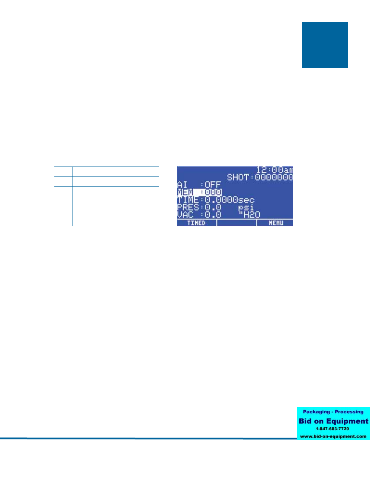
• Press the power switch to turn on the dispenser. The Main screen will be displayed and show all the
dispensing parameters.The first time the dispenser is powered up, all settings will be preset to zero.
AI Auto Increment Function
MEM Current Memory Address
TIME Dispensing Time
PRES Dispensing Pressure
VAC Vacuum
SHOT Dispense Counter
Dispensing Status (shown as icons)
INITIAL SETTINGS
17
BASIC MENU OPERATION
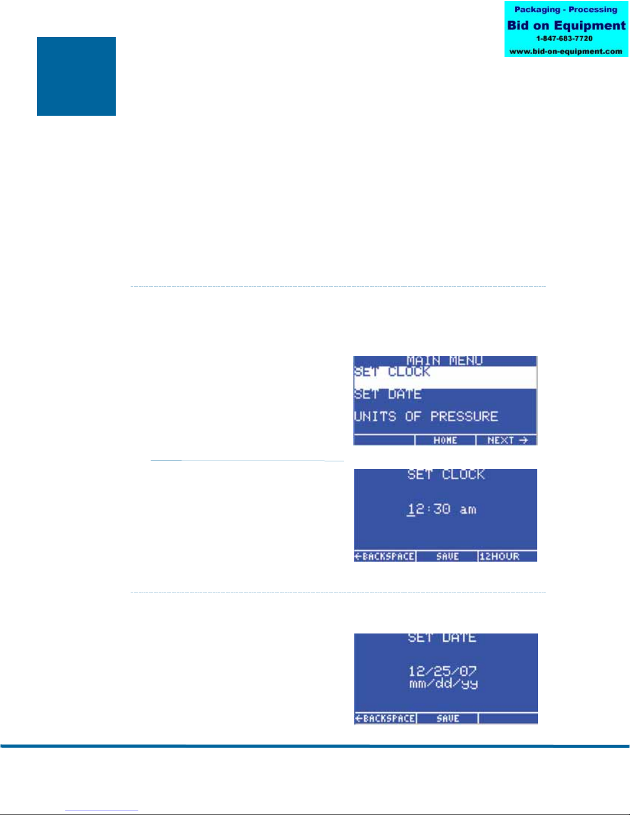
• From the Main screen, Press the F3 (Menu) key to display the first Main Menu screen.
• Use the Up/Down (8/2) keys to move through the individual menu items.
• Press the Enter key to display the screen for the highlighted item.
• Use the Up/Down (8/2) keys to scroll through and select individual items.
• Press the F2 (Save) key to confirm your selection.
• Use the F1 (Previous) and F2 (Next) keys to display the previous/next menu screen.
• Press the F2 (Home) function key to return to the Main screen.
• If a menu item is locked out via the Operator Lockout screen, that menu item will be
blanked out and cannot be selected.
Setting the Real Time Clock
Highlight SET CLOCK on the Main Menu screen,
then press the Enter key.
• Press the F3 function key to select 12 hour or 24
hour format, then enter the time.
Note: A leading zero must be used as required.
For example:
Time 12 hour format 24 hour format
5:30 am 05:30 am 05:30
1:30 pm 01:30 pm 13:30
• If 12 hour format is used, Press 1 for am or
2 for pm after entering the time.
• Press the F2 (Save) key to save this setting.
Setting the Date
• Highlight SET DATE on the Main Menu screen, then
press the Enter key.
• Enter the date in MM/DD/YY format
• Press the F2 (Save) key to save this setting.
Basic Menu
Operation
www.efd-inc.com [email protected] USA & Canada 800.556.3484 Europe +44 (0) 1582 666334 Asia & China: +86 (21) 3866 9006
Sales and service of EFD®dispensing systems are available worldwide.
18
Basic Menu
Operation
www.efd-inc.com [email protected] USA & Canada 800.556.3484 Europe +44 (0) 1582 666334 Asia & China: +86 (21) 3866 9006
Sales and service of EFD®dispensing systems are available worldwide.
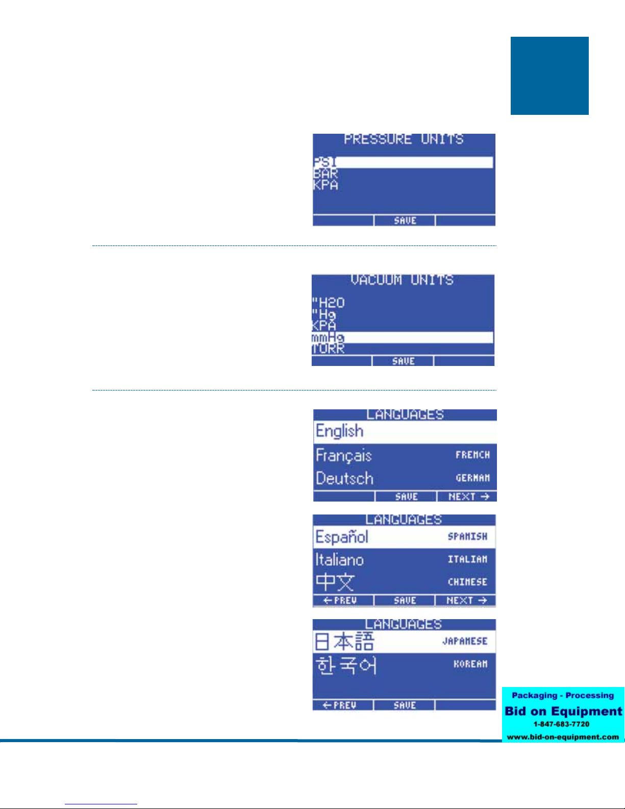
Setting Units of Pressure
• Highlight UNITS OF PRESSURE on the Main Menu
screen, then press the Enter key.
• Use the Up/Down (8/2) keys to select the unit type.
• Press the F2 (Save) key to save this setting.
Setting Units of Vacuum
• Highlight UNITS OF VACUUM on the Main Menu
screen, then press the Enter key.
• Use the Up/Down (8/2) keys to select the unit type.
• Press the F2 (Save) function key to save this
setting.
Setting Language
• From the Main screen, press the F3 (Menu) key to
display the Main Menu.
• Press the 2 (Down Arrow) button on the keypad until
the desired Language is highlighted, then press the
F2 (Save) key to confirm your selection.
• Press the F2 key to return to the Main screen,
where data will be displayed in the language you
just selected.
19

Basic Menu
Operation
Setting Operator Lockout Parameters
• From the Main screen, Press the F3 (Menu) key to
display the Main Menu Screen.
• Use the Up/Down (8/2) keys to highlight OPERATOR
LOCKOUT, then press the Enter key.
• The Password screen will be displayed.
Note: The Ultimus V dispenser is shipped with the
password preset to 0000.
Enter the 4-digit security code, then press the Enter key. An incorrect password will clear the digits and
redisplay the dashes.
General Operator Lockout Procedures
The following items can be locked out to prevent unauthorized adjustment:
Note:
• If a square is checked, it means that item has been locked out and the user cannot change or select
that item.
• To lock out an item, press the Up/Down (8/2) keys to highlight the desired item. Press the Enter key to
toggle the lockout setting on and off.
• Press the F3 (Next) key to load the next Operator Lockout screen. Press the F1 (Previous) key to load
the previous Operator Lockout screen. When finished, press the F2 (Save) key to save the settings
and return to the Main Menu screen.
• It is also possible to lock out the entire Main Menu so that when the user presses the Menu Function
key on the Main screen, the Password screen appears first. When the correct password is entered,
the Main Menu screen will load.
• When the Time Setting parameter is locked out, the deposit time duration cannot be adjusted and the
Teach dispense mode will also be locked out.
• When the F1 (Dispense Mode) key is locked out, the Ultimus will remain in the current Dispense Mode
(Timed or Steady) and cannot be changed.
• Locking out the Set Clock item will also lock out the Set Date item.
• The user can be locked out from resetting the dispensing parameters back to the starting address
before the Ultimus V reaches the ending address and the final trigger value by checking the Auto
Increment Reset option.
• Resetting the Alarms can be locked out. The user will be asked for the password when a latched
alarm is being reset.
• Time Setting
• Pressure Setting
• Vacuum Setting
• Memory Setting
• Deposit Counter
• Dispense Mode
• Auto Increment Mode
• Auto Increment Reset
• Alarm Reset
• Main Menu
• Pressure Units Menu
• Vacuum Units Menu
• Language Menu
• Set Comm Menu
• Alarms Menu
20
Table of contents
Other EFD Dispenser manuals


