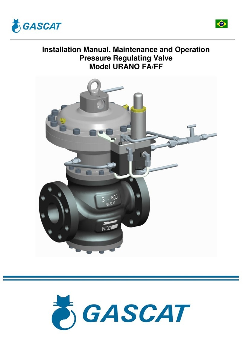
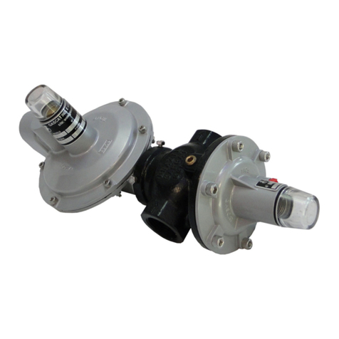
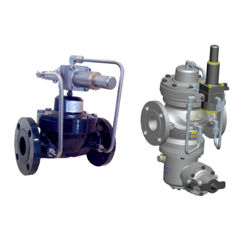
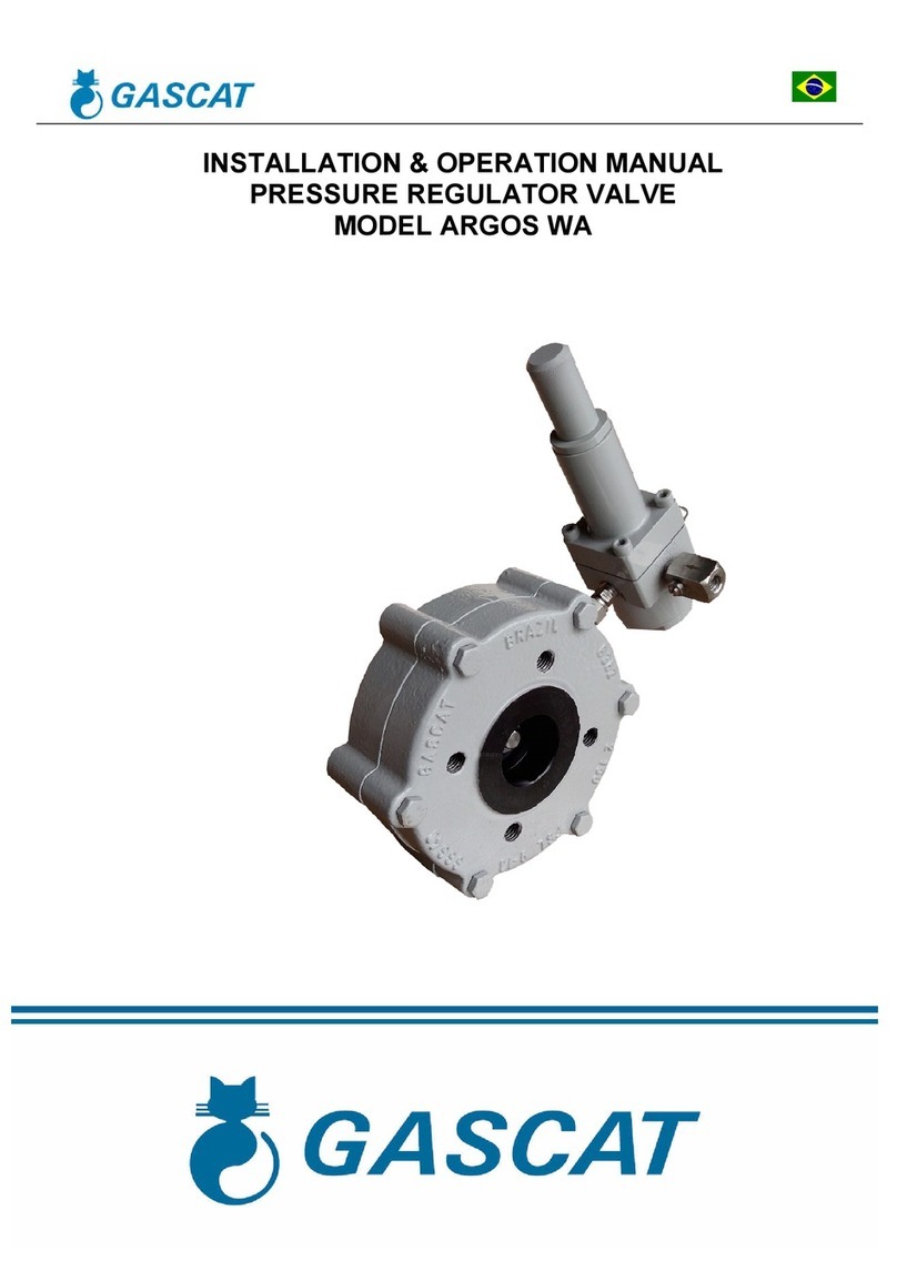
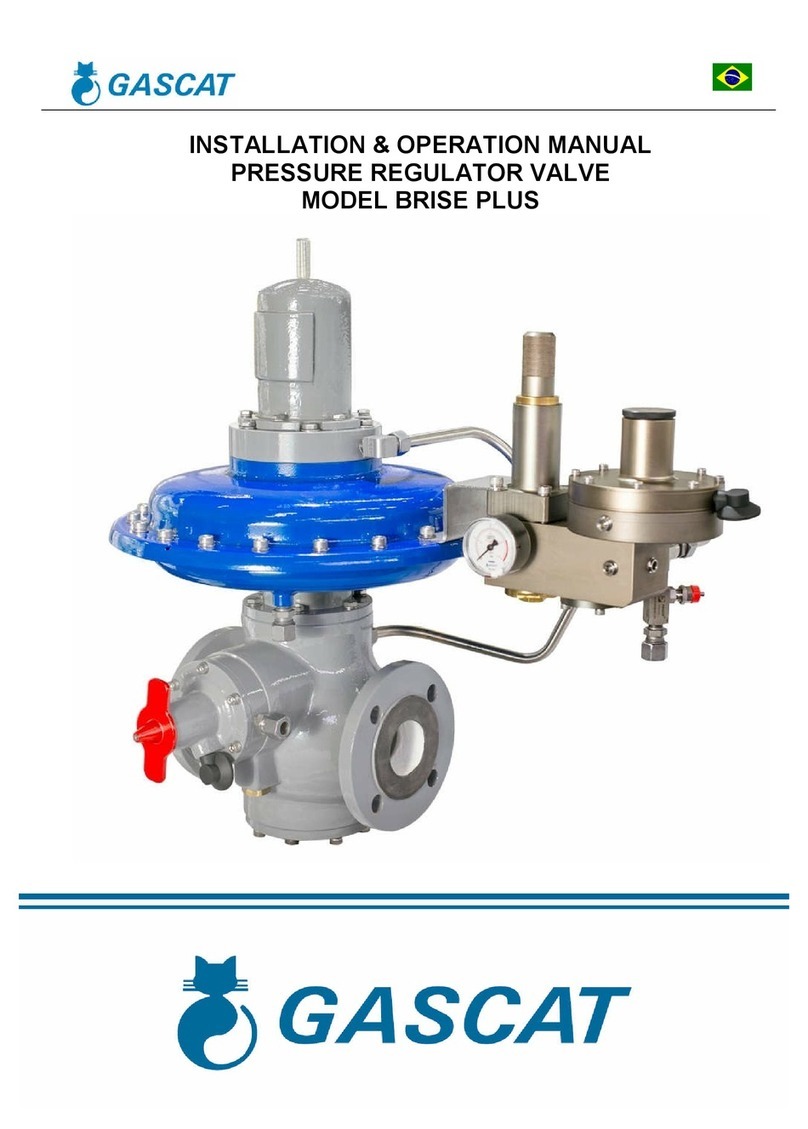
Gascat HORUS User manual

Installation Manual, Maintenance and Operation
Pressure Regulating Valve
Model HORUS Spring to Close

Installation Manual, Maintenance and Operation
Pressure Regulating Valve – Model Horus
MI-18
Elaborate
Verified / Approved
CSQ
Date
Review
Page
J.Junior Celso Nieto JM 25/11/16
04 2 de 32
INDEX
1.0 - GENERAL WARNINGS .......................................................................................................................................................... 3
1.1 – INSTRUCTIONS FOR COMMISSIONING .................................................................................................................................... 3
1.2 – HEALTH AND SAFETY ............................................................................................................................................................... 3
1.2.1 – NOISE ............................................................................................................................................................................... 3
1.2.2 – INSTALLATION ................................................................................................................................................................. 3
1.2.3 – OPERATION ...................................................................................................................................................................... 3
1.2.4 – MAINTENANCE ................................................................................................................................................................ 4
2.0 – INTRODUCTION ................................................................................................................................................................... 4
2.1 SCOPE OF MANUAL .................................................................................................................................................................... 4
2.2 DESCRIPTION .............................................................................................................................................................................. 4
2.3 SPECIFICATIONS ......................................................................................................................................................................... 5
2.3.1 AVAILABLE SETTINGS .......................................................................................................................................................... 5
2.3.2 AVAILABLE CONNECTIONS.................................................................................................................................................. 5
2.3.3 TEMPERATURE LIMITS ........................................................................................................................................................ 5
2.3.4 COEFFICIENTS FLOW ........................................................................................................................................................... 5
2.3.5 APPROXIMATE WEIGHT ...................................................................................................................................................... 6
2.3.6 MAXIMUM WORKING PRESSURE ...................................................................................................................................... 6
2.3.7 SETTING PRESSURES (SET-POINT) ....................................................................................................................................... 6
2.3.8 ACCURACY AND LOCK UP ................................................................................................................................................... 7
3.0 – PRINCIPLE OF OPERATION ................................................................................................................................................... 7
3.1 REGULATOR SPRING TO CLOSE (FAIL CLOSE) .............................................................................................................................. 7
3.2 BOOSTER (G-43) ......................................................................................................................................................................... 9
3.3 PILOTS (G-40 & G-42) ............................................................................................................................................................... 10
3.4 FILTERS ..................................................................................................................................................................................... 11
4.0 – INSTALLATION ................................................................................................................................................................... 11
4.1 FILTER ....................................................................................................................................................................................... 11
4.2 CLEANING ................................................................................................................................................................................. 11
4.3 DIRECTION OF FLOW AND SYSTEM INTEGRITY ......................................................................................................................... 11
4.4 SENSE ....................................................................................................................................................................................... 12
4.5 SCHEME RECOMMENDED INSTALLATION ................................................................................................................................ 13
4.5.1 SINGLE REGULATOR ......................................................................................................................................................... 13
4.6 START-UP ................................................................................................................................................................................. 14
4.6.1 GENERAL RECOMMENDATIONS ....................................................................................................................................... 14
4.6.2 COMMISSIONING (SINGLE REGULATOR) ......................................................................................................................... 15
4.6.3 ADJUSTING THE LINE BOOKING ........................................................................................................................................ 16
4.6.4 LIST OF RECOMMENDED TOOLS ....................................................................................................................................... 17
5.0 TROUBLE SHOOTING ............................................................................................................................................................ 17
6.0 MAINTENANCE .................................................................................................................................................................... 19
6.1 RECOMMENDED REPAIR PARTS AND KITS ............................................................................................................................... 20
6.2 PROCEDURE FOR REMOVAL THE PILOT G-40 / 42 .................................................................................................................... 25
6.3 PROCEDURE FOR ASSEMBLY THE PILOT G-40 / 42 .................................................................................................................... 27
6.4 PROCEDURE FOR REMOVAL BOOSTER (PRE-REGULATOR) G-43 .............................................................................................. 28
6.5 PROCEDURE FOR ASSEMBLY BOOSTER (PRÉ REGULATOR) G-43 .............................................................................................. 31
6.6
LIST OF RECOMMENDED TOOLS FOR MAINTENANCE .............................................................................................................. 32

Installation Manual, Maintenance and Operation
Pressure Regulating Valve – Model Horus
MI-18
Elaborate
Verified / Approved
CSQ
Date
Review
Page
J.Junior Celso Nieto JM 25/11/16
04 3 de 32
1.0 - GENERAL WARNINGS
1.1 – INSTRUCTIONS FOR PRE COMMISSIONING
It should be clearly understood that with the information presented in Commissioning Instructions that follow, it is not
intended to repeal or replace the instructions determined by any other competent body and should be reference to the
relevant standards and / or existing recommendations on this subject.
Before any commissioning, is implied the performance of the appropriate "Cleaning and Purification Procedures" that
must be observed and all the instructions on "Pressurization" and "Work Standards for Health and Safety", must be strictly
met.
The recommendations of valves suppliers, such as "open slowly" or "open very slowly" should be strictly observed.
1.2 – HEALTH AND SAFETY
Regulators, valves, and other pressurized components that contain toxic gases, flammable or other hazardous
products, are potentially dangerous if not operated and maintained properly. It is imperative that all users of this equipment
are adequately educated and guided to the potential hazards and make sure that staff responsible for the installation,
testing, commissioning, operation and plant maintenance are competent to do this. Instruction manuals are provided for the
guidance of operators, but it is assumed that they have a basic level of knowledge. If any doubts or ambiguities that affect
the proper procedures ask Gascat Ind e Com. Ltda. who will be happy to advise or provide the relevant service or
instruction. NO RISK. Our phone number, fax number and e-mail are described below:
Gascat Indústria e Comércio Ltda.
Rodovia SP 73, 1141 – Indaiatuba / São Paulo.
CEP 13347-990
Telefone: +55 19 3936-9300
Fax: +55 19 3935-6009
Email:
The comments that follow, while not exhaustive, provide guidance possible sources of danger to health and safety.
1.2.1 – NOISE
Regulators, valves and pressure reducers can produce high noise levels, which may be harmful to persons exposed to
them for long periods of time. Users should ensure that adequate precautions are taken in order to provide security to the
health of employees and / or third parties as the standards and recommendations in force.
1.2.2 – INSTALLATION
All equipment, piping and vessels are designed to withstand mechanical stress, for example, torque and moments of
"bending" in addition to internal pressure. However, care must be taken during installation to not impose excessive strain,
which may cause cracks that may result in a more serious break when the regulator is put into operation. Excessive stress
can also be caused due to not supporting the length of the pipe, which must be adequately supported.
All regulators, valves shut off, relief valves, etc., should be installed with the correct flow.
Impulse lines are important components of any control system and it is essential that they are properly installed and
without isolation valves.
Impulse lines should be adequately supported to reduce excessive vibration which may cause disruption due to fatigue.
They should also be positioned so that they cannot serve as a footrest or hands. Impulse lines should be slightly inclined
so that condensed liquids and to flow into the main pipe.
When necessary (in underground facilities or indoor area) should be installed a pipe ventilation from Ø threaded ¼
"NPT, positioned in the bell or diaphragm housing, which should be extended and positioned in a safe place and ventilated,
with the departure of protected vent to prevent water entering the rain and insects that may cause obstruction of ventilation.
Auxiliary systems should not be altered or modified without the knowledge of operating conditions and permission of the
people responsible.

Installation Manual, Maintenance and Operation
Pressure Regulating Valve – Model Horus
MI-18
Elaborate
Verified / Approved
CSQ
Date
Review
Page
J.Junior Celso Nieto JM 25/11/16
04 4 de 32
1.2.3 – OPERATION
Depending on the type of regulator, the valve may even be positioned fully open. Consequently, when a regulator put in
operation, the shutoff valves should be opened slowly so that the regulator valve can assume its regulating position. If the
valves are quickly opened the upstream pressure can pass downstream through the regulator and over-pressurize
downstream the main line.
All regulators, etc., should operate with the spring adjustment specified by the manufacturer. This is especially important
when operating relief valve or shutoff valves, since incorrect springs may prevent the relief valve to open and close the
shutoff valve.
Precautions should be taken to prevent water from entering through the openings for breathing and ventilation.
1.2.4 – MAINTENANCE
Regulators and valves contain gases at pressures that are sometimes greater than atmospheric pressure. Before trying
to investigate any problem or perform maintenance work on equipment, they must be safely depressurised. Furthermore,
as most gases may be flammable, toxic, corrosive, or hazardous, it may be necessary to purge the system with an inert
gas such as nitrogen. Special precautions are necessary for operation with gases such as oxygen or hydrochloric gas and
the user must be sure that the appropriate procedures are in place.
Eventually it is not enough to isolate the high pressure device, since high pressures can be retained downstream of
isolation valves. Do not try to remove covers, plugs, etc., before this device is properly released. Still, it is wise to consider
that the high pressure gas may be present when removing covers and plugs.
Most regulators use spiral springs as a charging device. It is important to reduce the burden these springs away your
presser as possible. In some cases, there may be some cargo residue, even when the spring is relaxed within the limits of
their house.
2.0 – INTRODUCTION
2.1 SCOPE OF MANUAL
This manual aims to provide operational information, installation and maintenance of the pressure regulators model
HORUS manufactured by GASCAT.
2.2 DESCRIPTION
The pressure regulator model HORUS was designed to meet varied applications and to work with several process
service conditions. It has outstanding applications with high differential pressure combined with high process flow and high
pressure. It are typical installations with these characteristics the natural gas transportation and delivery points where
occurs custody transference. It is also common to utilize with distributor stations of natural gas and other gases non-
corrosive.
The pressure regulator HORUS is pilot operated and has axial flow what result in low noise level as well high flow
capacity. Beyond this, the double diaphragm pilots supplied with the valve allow accuracy in set pressure up to 1%.
It’s construction design meets the active (fail open) monitor (fail close) configuration.
The set of piston and seat was designed to proportionate high flow rangeability to the pressure regulator, can operate
with a maximum inlet pressure of 150 kgf/cm² and outlet pressures from 1.0 to 80.0 kgf/cm².

Installation Manual, Maintenance and Operation
Pressure Regulating Valve – Model Horus
MI-18
Elaborate
Verified / Approved
CSQ
Date
Review
Page
J.Junior Celso Nieto JM 25/11/16
04 5 de 32
2.3 SPECIFICATIONS
2.3.1 AVAILABLE SETTINGS
HORUS FC: Pilot operated pressure regulator fail close position
2.3.2 AVAILABLE CONNECTIONS
DN FLANGE ASME B16.5 FLANGE DIN 2634 / 2635
2” 150#RF / 300#RF / 600#RF ou RTJ / 900#RF ou RTJ PN 25 / PN 40
3” 150#RF / 300#RF / 600#RF ou RTJ / 900#RF ou RTJ PN 25 / PN 40
4” 150#RF / 300#RF / 600#RF ou RTJ / 900#RF ou RTJ PN 25 / PN 40
6” 150#RF / 300#RF / 600#RF ou RTJ / 900#RF ou RTJ PN 25 / PN 40
8” 150#RF / 300#RF / 600#RF ou RTJ / 900#RF ou RTJ PN 25 / PN 40
10” 150#RF / 300#RF / 600#RF ou RTJ / 900#RF ou RTJ PN 25 / PN 40
2.3.3 TEMPERATURE LIMITS
Operating temperature: -20°C a 60°C
Ambient temperature: -20°C a 60°C
Temperature limits reported in this manual or any standard should not be exceeded under any circumstances, at the
risk of damage to the equipment, installation and security of the people involved in the operation.
2.3.4 COEFFICIENTS FLOW
DN CV KG
2” 80 2481
3” 161 5024
4” 320 9924
6” 610 18920
8” 1119 34735
10” 1750 54275
Note:
1) We suggest that is considered a 20% safety factor on the calculated value.
2) When assembled in an active-monitor system consider 25% restriction on the CV / KG of both valves.

Installation Manual, Maintenance and Operation
Pressure Regulating Valve – Model Horus
MI-18
Elaborate
Verified / Approved
CSQ
Date
Review
Page
J.Junior Celso Nieto JM 25/11/16
04 6 de 32
2.3.5 APPROXIMATE WEIGHT
DN 150# 300# 600#
2” 64 65.5 67.5
3” 93 97 99
4” 147 150 157
6” 280 300 340
8” 580 610 650
10” 812 854 905
Note:
1) Weights reported in kilograms (Kg)
2) Considered body in carbon steel SA-216 WCB
3) For the exact weights contact the GASCAT for verification of the model.
2.3.6 MAXIMUM WORKING PRESSURE
150# 300# 600# 900# PN 25 PN 40
19 bar 51 bar 100 bar 150 bar 25 bar 40 bar
Pressure limits reported in this manual or any standard should not be exceeded under any circumstances, at the risk of
damage to the equipment, installation and security of the people involved in the operation.
2.3.7 SET-POINT
Pressure regulators, model HORUS use two models of pilots for pressure control called G-40 and G-42, here are the
adjustment ranges available for each model:
G-80 PILOT
SPRING COLOR PART NUMBER RANGE
YELLOW / GREY 01.50.09 20 – 50 mbar
BLUE 01.50.10 45 – 100 mbar
WHITE / GREY 01.50.21G 90 – 250 mbar
SILVER 01.50.21P 150– 430 mbar
GREY 01.50.24 340 – 1100 mbar
PILOT G-40
SPRING COLOR CODE ADJUSTMENT RANGE
RED 01.51.94A 25,0 – 50,0 bar
YELLOW 01.51.94 47,0 – 80,0 bar

Installation Manual, Maintenance and Operation
Pressure Regulating Valve – Model Horus
MI-18
Elaborate
Verified / Approved
CSQ
Date
Review
Page
J.Junior Celso Nieto JM 25/11/16
04 7 de 32
PILOT G-42
SPRING COLOR CODE ADJUSTMENT RANGE
GREEN 01.49.65 1,0 – 4,5 bar
GRAY 01.49.64 4,5 – 12,0 bar
BLUE 01.49.33 11,0 – 17,0 bar
RED 01.51.94A 16,0 – 30,0 bar
YELLOW 01.51.94 27,0 – 55,0 bar
2.3.8 ACCURACY AND LOCK UP
Accuracy; Closing: AC up to 1; SG up to 2,5
3.0 – PRINCIPLE OF OPERATION
3.1 REGULATOR SPRING TO CLOSE (FC)
During pressure absence, shutter (A) is kept in closed position by the shutting spring (B), which keeps it pressed
against the gasket (C). It stands out that even when subject to pressure, upstream pressure variations have no influence
on the shutter position, due to the balancing of the forces acting on the same, as well as on the actuator shaft (D) that is
also balanced.
When the inlet piping is pressurized, gas reaches the booster (F), which reduces the pressure to a convenient value
near to the outlet pressure and delivers the same to pilot (G). The pilot compares the gas feeding pressure with the outlet
pressure, sensed by the pilot diaphragm (H), and controls the flow to be injected under the main regulator diaphragm (L).
If a decrease in downstream pressure occurs (due to an increased consumption or a drop of the upstream pressure)
an imbalance between the spring (I) force on the pilot (H) diaphragm and the force generated by the outlet pressure under
this same diaphragm, drives the pilot (K) shutter to a larger aperture, therefore, causing a pressure increase under the
main regulator (L) diaphragm, which combined with downstream pressure drop, which actuates on the main regulator
diaphragm and in the opposite side of the pilot pressure thereon, will determines the displacement of the shutter (A)
upwards, thereby increasing the passage and restoring the set point.
When the pre-regulated pressure begins to increase, it makes the pilot (K) shutter to reduce the aperture. The
increased pressure, which actuated under the regulator (L) diaphragm, flows through the Bleed (M) restriction (adjustable)
that discharges the same downstream. The strength of the closing spring of the main regulator (B) plus the decrease of the
pilot pressure cause a downward displacement of the main shutter (A), making the pressure to return to the preset value.

Installation Manual, Maintenance and Operation
Pressure Regulating Valve – Model Horus
MI-18
Elaborate
Verified / Approved
CSQ
Date
Review
Page
J.Junior Celso Nieto JM 25/11/16
04 8 de 32
FIGURE 1 - HORUS FAIL CLOSED
F
A
D
B
M
I
G
L
K
C
H

Installation Manual, Maintenance and Operation
Pressure Regulating Valve – Model Horus
MI-18
Elaborate
Verified / Approved
CSQ
Date
Review
Page
J.Junior Celso Nieto JM 25/11/16
04 9 de 32
3.2 BOOSTER (G-43)
The Booster is nothing more than a pre-regulator that automatically adjusts the process conditions as a function of the
input pressure and output pressure with the purpose of reducing the pilot inlet pressure, allowing the pilot to operate in a
milder condition, thus eliminating any chance of interference on the regulator piloting by the input pressure variation.
The use of a pre-regulator, or booster, is recommended only for applications where the pressure differential exceeds
10.0 bar.
Booster models G-43 and G-44 are designed to keep the pilot input pressure set 1 to 2 bar above the desired set point,
e.g.: if we are adjusting the pressure regulator to 20 bar, the booster will be applying to the pilot a pressure of 21 to 22 bar.
Typically, the booster G-43 have three connections to the process. These are represented by the red line in the figure
above, from the regulator inlet and loaded with the inlet pressure; the yellow line is the output pressure of the main
regulator, also called sensor pick-up, and is responsible for actuating on the booster diaphragm (A), moving the shaft (B)
away from the gasket (C), thus allowing the passage of gas from the regulator input at a pressure 1 to 2 Kgf/cm² above the
set point pressure of the main regulator, which by its turn is represented by the green color and is the pick-up that will
follow to the Pilot.
Attention: In some assemblies, the booster can be integrated into the pilot; this change is merely ergonomic to reduce
space, component count and ease of operation. However, it is important to note that the operating principle is exactly the
same as given above.
A
B
C

Installation Manual, Maintenance and Operation
Pressure Regulating Valve – Model Horus
MI-18
Elaborate
Verified / Approved
CSQ
Date
Review
Page
J.Junior Celso Nieto JM 25/11/16
04 10 de 32
3.3 PILOTS (G-40 & G-42)
The pilots series G-40 and G-42 are composed by dual diaphragm pilot that can achieve much higher accuracy than
other pilots due to their constructional characteristics.
Pilots are responsible for sending the exact loading pressure for pressure regulating valves open or close under normal
process conditions by the balance between the force of the regulating spring and the outlet pressure received by the
sensor outlet.
The green line represents the pressure from the booster or pre regulator, the yellow line is the regulator outlet
pressure (sensor outlet) and this is responsible for moving the diaphragm assembly (A) upward or downward, causing the
driver shutter (B) move it away from the seat (C), thus permitting the reduction in inlet pressure and sending the
appropriate gas pressure to perform charging of the main valve causing the valve to open or close according to the
process conditions.
A
B
C

Installation Manual, Maintenance and Operation
Pressure Regulating Valve – Model Horus
MI-18
Elaborate
Verified / Approved
CSQ
Date
Review
Page
J.Junior Celso Nieto JM 25/11/16
04 11 de 32
3.4 FILTERS
The GASCAT called pilot blocks consisting of pilot and booster has always a mechanical barrier against solid
impurities, this barrier is composed by a filter element in polypropylene with filtration degree of 10 microns.
This barrier aims to prevent solid contaminants in the pipe can clog or damage the internal pre regulator and the pilot,
but it is important to note that this filter does not replace the filtration system that should be provided in the
previous steps to pressure regulating so as to leave the clean fluid and correct operating conditions, the filter is
designed to serve as a last barrier to the solid contaminants.
The HORUS pressure regulators are available with F-10 filter, mounted separate from the pilot block or compact
version with the filter element already attached to the pre regulator.
4.0 – INSTALLATION
4.1 FILTER
We recommend installing a filter type "cartridge", with grade 5 Micra filtration, as close to the regulator inlet, without
being united flange to flange, therefore, the filter installed immediately upstream of the regulator may cause turbulence
causing disturbance in the regulator pressure control. Care for the filter installation is essential to the smooth operation of
the instrument as any existing particles in the pipe can become lodged between the seat and the shutter, damaging them
and causing feedthrough.
4.2 CLEANING
Check the pipe cleaning before valve installation. We recommend a complete purge of the line with nitrogen or
compressed air.
4.3 DIRECTION OF FLOW AND SYSTEM INTEGRITY
Before proceeding with the installation of the equipment you must ensure that:
1) The equipment is in perfect condition or has function in damaged evidence in the handling during transport, if
you have a fault not proceed with the installation and contact the GASCAT.
2) The area in which access and installation of the equipment is suitable, including for future maintenance.
3) The facility was designed to support the load imposed by equipment.
4) The input and output connections where the pressure regulator is installed are perfectly aligned.
5) All outlets of necessary pressure in the pipeline downstream equipment for sensing, were provided and are
respecting the dimensions recommended by the manufacturer.
6) It was predicted gauge or any other equipment upstream pressure indicator and downstream equipment to
allow the correct fit for the start-up.
7) was provided a line of vent between the regulator and the first output block valve to assist the operator during
start-up.
8) Check the direction of flow of the body marked throttle valve and pay attention to the time of installation so that
it is properly positioned.

Installation Manual, Maintenance and Operation
Pressure Regulating Valve – Model Horus
MI-18
Elaborate
Verified / Approved
CSQ
Date
Review
Page
J.Junior Celso Nieto JM 25/11/16
04 12 de 32
4.4 SENSE
The correct positioning of making impulse in the pipeline is essential for the proper functioning of the throttle valve,
therefore install the pilot impulse outlet regulator downstream at a minimum distance of 5 times the nominal pipe
diameter and stretch obstruction-free pipe with a pipe diameter where the gas flow rate does not exceed the maximum
speed of 25 m / s (considering the lower output pressure and the maximum flow).
To obtain a better pneumatic signal, use ½ OF tubbings "stainless steel AISI 316 to connect the regulator to the
process.
In order to avoid the accumulation of impurities and condensate in the impulse taken recommend that they be
installed with a slope of 5% to 10% towards the connector on the pipe.
Pay attention to the connections welded pipe for it to be totally clear, without any welding residue that could
interfere with pneumatic signal.
Each throttle model HORUS SC (FF) needs three process connections: one directly to the actuator on the
diaphragm, one that will be connected directly below the pilot and a third for the purpose of discharging the actuator
under the diaphragm.
They should be installed block valves of any kind into the pressure
regulators pulse taken.
UNLOADING LINE
SENSING LINE PILOT
SENSING LINE VALVE
FRONT VIEW
REAR VIEW

Installation Manual, Maintenance and Operation
Pressure Regulating Valve – Model Horus
MI-18
Elaborate
Verified / Approved
CSQ
Date
Review
Page
J.Junior Celso Nieto JM 25/11/16
04 13 de 32
4.5 SCHEME RECOMMENDED INSTALLATION
4.5.1 SINGLE REGULATOR
1 – Inlet shut-off valve 6 – Partial relief valve
2 – Filter cartridge type degree of filtration 5 micra 7 – Output pressure gauge + manifold 2 way
3 – Entry gauge + manifold 2 way 8 – Valve vent
4 – Automatic shut-off valve for over pressure (SSV) 9- Output block valve
5 – Pressure regulator valve model URANO GASCAT
Note: The position indicated for the sensor outlet may be less than 5D from the installation project to be reviewed and
approved by engineering GASCAT.
Another recommended installation option is the use of a lung to connect the sensor taken near the equipment, among
the advantages of adopting this configuration include:
1) Greater convenience during maintenance.
2) Pneumatic signal of better quality (stable).
3) Reduction of damage to tubbings during maintenance and transport.
Note: The position indicated for lung outlet may be less than 5D from the installation project to be reviewed and
approved by engineering GASCAT.

Installation Manual, Maintenance and Operation
Pressure Regulating Valve – Model Horus
MI-18
Elaborate
Verified / Approved
CSQ
Date
Review
Page
J.Junior Celso Nieto JM 25/11/16
04 14 de 32
4.6 START-UP
4.6.1 GENERAL RECOMMENDATIONS
Before proceeding with the commissioning of the equipment is important to always:
1) Check that the equipment is properly installed according to the recommendations set out in item 4.3 of this
manual.
2) Close the input block valves, output and bypass (if applicable) of the leg.
3) Open the vent valve downstream of the last pressure regulator installed on leg.
4) Make sure that the depressurized this station.
5) Make sure all connectors are properly secured the station before proceeding with the pressurization of the
line.
6) Check that the installed equipment is suitable operating conditions through the information available on the
nameplate attached to the equipment.
7) Make sure the SSV is in the closed position.
ATTENTION:
* Under no circumstances do with the line pressurization where the
equipment is installed by the posterior valve equipment.
* Under any circumstances perform depressurization line where
equipment is installed by the valve located at the entrance of the
equipment, such as filters drain.
ATTENTION:
The SSV GASCAT are sent to the already calibrated field, however due
to the conditions of carriage and operation of any equipment the valve
may have its set-point change.
Therefore we recommend that you checked the set-point of the SSV
with the help of a connected external air supply directly to the actuator,
before proceeding with the pressurization of the line.
The model HORUS valves are not sent to field set on their set-point, this
measure tends to preserve the life of the product's internal therefore to
receive a control valve HORUS model pressure, keep in mind that you
need to perform the adjustment set-point before putting the equipment
into operation.
The setting of the pressure reducing station should be in accordance with DIN EN 12186 / NBR 12712 and
all other applicable regulations in the region where it will operate.

Installation Manual, Maintenance and Operation
Pressure Regulating Valve – Model Horus
MI-18
Elaborate
Verified / Approved
CSQ
Date
Review
Page
J.Junior Celso Nieto JM 25/11/16
04 15 de 32
4.6.2 COMMISSIONING (SINGLE REGULATOR LINE)
Using as reference the assembly scheme presented in section 4.5.1 we will proceed with the description indicated
for HORUS model regulator commissioning a simple adjustment line, considering that the recommendations made
in section 4.6.1 of this manual have been properly observed.
The procedure in question considers the use of GIPS-FC GASCAT model valves as a safety device.
1) Fec
Close the vent valve.
As the line shut-off valves are closed we will use the vent valve to simulate a small flow and do so with the
regulator adjustment before aligning the line.
2) Check that the pilot of the regulating spring is properly relieved (discharged).
Relieving regulating spring we are ensuring that the valve will remain in the closed position when pressurized.
3) Make sure the unloading valve (needle valve) is open in 1/8 turn.
4) SLOWLY AND GRADUALLY open the shut-off valve, or when the station is provided with a by-pass valve
block uses the same to carry out pressurization.
5) Since there is no regulator downstream pressure shut-off valve GIPS-FC model will be in the closed position,
so keep the bypass valve located on the side of the SSV pressed to pressurize the space between it and the
regulator pressure.
6) While still holding the valve bypass the SSV, proceed with placing a light load on the pilot's regulating spring in
order to admit a small downstream pressure control valve, use a pressure gauge to monitor the increase of
this pressure and let the pressure adjusted to a value at least 20% above the set-point of low pressure SSV.
DISCHARGE VALVE

Installation Manual, Maintenance and Operation
Pressure Regulating Valve – Model Horus
MI-18
Elaborate
Verified / Approved
CSQ
Date
Review
Page
J.Junior Celso Nieto JM 25/11/16
04 16 de 32
7) Once the actuator SSV is already pressurized, release the by-pass valve and proceed with the disengagement
of the actuator of the SSV.
8) Reset the shutter GIPS-FC block valve, through the reset lever.
9) Open the vent valve at 20%, make sure the pressure will continue in pre-set value.
10) Using a combination wrench 7/8 "turn the adjustment screw clockwise to increase the output pressure to the
value of set-point desired.
11) If the pressure is oscillating perform a fine adjustment by opening or closing the discharge valve.
12) If the pressure is oscillating perform the fine adjustment by opening or closing the discharge valve.
13) Being set pressure according to the desired value, close the vent valve and check valve lock up.
14) Check for leakage in connectors and other throttle connections to the line.
15) Open SLOWLY AND GRADUALLY the output shut-off valve to put the line into operation.
16) If necessary to perform fine-tune the set pressure through the pilot regulating spring.
4.6.3 ADJUSTING THE LINE BOOKING
When the regulator is installed in a reserve line recommend that you performed the same procedure reported in
4.6.2, but the set-point pressure regulator should be adjusted for a 15% pressure - 20% less than the valve set-
point that is in operation.
Made it open SLOWLY AND GRADUALLY downstream so that the pressure outlet shut-off valve to the regulator
leg reserves equalize with the pressure that is already in operation, the regulator reserves remain closed.
To make the regulator that the reservation leg assume the setting, press the regulating spring towards slowly
clockwise until the set-point of this regulator reaches a value greater than the set-point of the line is in operation,
this the way regulatory reserve will open slowly and take the operation.
It is important that the two regulators remain with a difference of set-point at least 5% - 10%, so there is not a set-
point of overlap causing a competition between the two lines, ie a minute regulator opens in governor opens
another booking, promoting an inaccuracy in regulating.
TABLE SET POINTS RECOMMENDED
SET POINT
MAIN REGULATOR (PS)
SET POINT
REGULATOR
RESERVE
SET POINT PSV SET POINT SSV
2,5 – 5,0 bar PS x 1,150 PS x 1,400 PS x 1,500
5,0 – 12,0 bar PS x 1,050 PS x 1,200 PS x 1,300
12,0 – 20,0 bar PS x 1,025 PS x 1,200 PS x 1,300
20,0 – 80,0 bar PS x 1,025 PS x 1,150 PS x 1,250
Note: The values in this table are recommendations based on best practices, but it is not prohibited the use of set-
points in different groups of informed upon review and approval of GASCAT.

Installation Manual, Maintenance and Operation
Pressure Regulating Valve – Model Horus
MI-18
Elaborate
Verified / Approved
CSQ
Date
Review
Page
J.Junior Celso Nieto JM 25/11/16
04 17 de 32
4.6.4 LIST OF RECOMMENDED TOOLS
To perform the adjustment set-point commissioning and start-up of regulatory URANO GASCAT the
model is required only the use of a combination wrench 7/8 "to adjust the regulation of pilots springs.
The valves are URANO model fornecdias with connectors for tubbing DN ½ "in the sensor plugs, so we still
recommend the use of combination wrenches 19 mm and 13/16" for fixing the sensor taken the process line.
ND 1 2
1”,2”,3”,4”,6”, 8” and 10” 19 mm, 7/8” e 13/16” 1”
5.0 TROUBLE SHOOTING
This section of the manual aims to show potential field problems and their causes.
The problems listed in this section may be from different situations, but most of them is related to the gas
conditions (impurities), natural wear and failures during operation of the equipment.
It is important to keep in mind that the operation and maintenance of GASCAT equipment must be only carried out
by highly qualified and trained personnel, preferably by staff trained by GASCAT instructors.
For training and qualification of operators and technicians contact the GASCAT through the contacts below to
check availability.
E-mail: [email protected]
HORUS
PROBLEM PROBABLE CAUSE CORRECTIVE ACTION
Malfunction, outlet pressure oscillation
Low flow (less than 5% of the
maximum flow).
Check the operating conditions
and restore the flow conditions for
the standards to which the
equipment has been designed.
Making poorly localized impulse.
Adjust the position of the pulse
taken as reported in this manual,
or contact the GASCAT for
analysis of engineering.
Response speed of the regulator
incompatible with the system.
Adjust the unloading valve
(needle).
1
2

Installation Manual, Maintenance and Operation
Pressure Regulating Valve – Model Horus
MI-18
Elaborate
Verified / Approved
CSQ
Date
Review
Page
J.Junior Celso Nieto JM 25/11/16
04 18 de 32
Feedthrough or regulator locked in
the open position
Shutter (pos 48 SC; pos 57 SO) of
the locked main regulator
Adjust the unloading valve
(needle) .Check state shutter and
anti-friction rings proceeding
replacement or cleaning if
necessary (minimum of grease
should be applied to assembly of
these items, preferably using bi-
molybdenum sulfide).
Broken or damaged impulse line Check status of impulse line and
proceed to replace it if necessary.
Headquarters (pos 44 SO; pos 38
SC) damaged or particulate
matter between the shutter and
the seat.
Make cleaning and check state
headquarters, if it has no apparent
marks of damage proceed to the
assembly and check the lock up,
replace if damaged.
Disruption of the main diaphragm
(pos 3) of the FA valve (Spring to
open)
Replace the main diaphragm
Output pressure decrease and or
insufficient flow
Dirt on the filter Provide filter cleaning or replacing
the filter element.
Power Outage
1) Check the locking of the
booster shutter (G-43). Make sure
the pilot's seat is blocked.
Passage in the main diaphragm Replace the main diaphragm
Exhaust gas by the pilot cover the
breather. Breaking the diaphragm Replace the diaphragm.
Gas leak at door trim booster Booster trim disruption (G43) Replace the gasket.

Installation Manual, Maintenance and Operation
Pressure Regulating Valve – Model Horus
MI-18
Elaborate
Verified / Approved
CSQ
Date
Review
Page
J.Junior Celso Nieto JM 25/11/16
04 19 de 32
6.0 MAINTENANCE
Perform preventive maintenance of pressure regulators model URANO is essential for proper operation of the
equipment over time and is directly related to the reliability of the pressure control system, preventing the user operating
problems.
The frequency of maintenance varies considerably according to the installation, operating conditions and the quality
of the fluid in question, for example if the machine is subject to a large presence of contaminants such as black powder,
yellow powder, oil, condensate, etc. certainly the service interval should be lower.
The GASCAT own standards repair kits for each throttle component URANO model composed of the most likely
items to wear with time, this list of components that discriminated in this manual for the guidance of users.
Before starting maintenance pressure regulators in GASCAT always make sure to have a replacement kit with
original parts GASCAT as well as this instruction manual for reference and how to safely and efficiently while maintaining
the equipment.
ATTENTION:
The components of the control valves GASCAT pressure are developed,
manufactured and tested with GASCAT exclusivity in order to provide
the greatest efficiency and safety operation, not using original
components makes unsafe operation and compromises the process
efficiency.
The GASCAT not responsible for the operation of equipment that do not
operate with original components.

Installation Manual, Maintenance and Operation
Pressure Regulating Valve – Model Horus
MI-18
Elaborate
Verified / Approved
CSQ
Date
Review
Page
J.Junior Celso Nieto JM 25/11/16
04 20 de 32
6.1 RECOMMENDED REPAIR PARTS AND KITS
HORUS SC (FF)
Table of contents
Other Gascat Control Unit manuals
Popular Control Unit manuals by other brands

Goldline
Goldline AQL-BASE-RF Installation and operation guide

Harvia
Harvia SIGMA COMBI CS110C Instructions for installation

Sfar
Sfar SFAR-S-8AO user manual

Intel
Intel AXXTPME3 Hardware user's guide
Steady State Fate
Steady State Fate DivKid RND manual

Reliance electric
Reliance electric PSC7000 instruction manual
Continental Hydraulics
Continental Hydraulics A Design Series Service manual
Festo
Festo CAMC-G-S3 Translation of the original instructions

ZIMO
ZIMO MX9V instruction manual
Unex
Unex SOM-352 Series quick start guide
Viega
Viega 2235.2 Instructions for use

VAT
VAT 570 Series Installation, operating, & maintenance instructions
