Gascat URANO FA Instruction manual

Installation, Operation & Maintenance Manual
Pressure Regulating Valve
Model URANO FA/FF

Installation and Operation Manual
Urano - Pressure Regulating Valve MI-31
Elaborado Verificado / Aprovado CSQ Data Revisão Página
JJ JJ JM 05/07/21 05 2 de 74
TABLE OF CONTENTS
1.0 GENERAL WARNING 3
1.1 PRE-COMMISSIONING INSTRUCTIONS 3
1.2 - HEALTH & SAFETY 3
1.2.1 - NOISE 3
1.2.2 - INSTALLATION 3
1.2.3 - OPERATION 4
1.2.4. MAINTENANCE 4
2.0 INTRODUCTION 5
2.1 SCOPE 5
2.2 DESCRIPTION 5
2.3 SPECIFICATIONS 5
2.3.1 AVAILABLE CONFIGURATIONS 5
2.3.2 AVAILABLE CONNECTIONS 5
2.3.3 TEMPERATURE LIMITS 6
2.3.4 COEFFICIENT OF FLOW (Cv) 6
2.3.5 WEIGHTS 6
2.3.6 MAXIMUM WORK PRESSURE 7
2.3.7 SET POINT PRESSURES 7
2.3.8 SLAM SHUT VALVE SPRING RANGE (SET-POINT) 7
2.3.9 ACCURACY AND LOCK UP 8
2.3.10 PRESSURE REGULATOR DIMENSION 7
3.0 - OPERATION PRINCIPLE 8
3.1 REGULATOR SPRING TO CLOSE (FAIL CLOSE) 9
3.2 REGULATOR SPRING TO OPEN (FAIL OPEN) 11
3.3 BOOSTER (G-43 & G-44) 13
3.4 PILOTS (G-40 & G-42) 14
3.5 FILTERS 14
3.6 SECURITY SHUT-OFF VALVE 175
3.6.1 PH ACTUATOR & H ACTUATOR 15
3.6.2 GENERAL RESET PROCEDURE 15
3.6.3 SHUT-OFF RESET & INTEGRATED BYPASS PROCEDURE 16
3.7 ACTIVE MONITOR ASSEMBLY 17
4.0 - INSTALLATION 19
4.1 FILTER 19
4.2 CLEANING 19
4.3 FLOW DIRECTION AND SYSTEM INTEGRITY 19
4.4 IMPULSE PICK-UP 20
4.5 RECOMMENDED INSTALLATION SCHEME 22
4.5.1 SINGLE REGULATOR 22
4.5.2 ACTIVE MONITOR SYSTEM 24
4.5.3 TWO SSV AND ONE FF REGULATOR 27
4.6 COMMISSIONING AND START-UP 29
4.6.1 GENERAL RECOMMENDATIONS 29
4.6.2 COMMISSIONING (SINGLE REGULATOR SPAN) 30
4.6.3 THE BACK-UP LINE SET-UP 32
4.6.4 COMMISSIONING (ACTIVE MONITOR SYSTEM) 33
4.6.5 BACK-UP LINE SETUP (ACTIVE-MONITOR) 38
4.6.6 LIST OF RECOMMENDED TOOLS 38
5.0 TROUBLE SHOOTING 39
6.0 MAINTENANCE 40
6.1 RECOMMENDED REPAIR PARTS AND KITS 42
6.2 PROCEDURE FOR URANO SC (FF) REGULATOR DISASSEMBLY 51
6.3 PROCEDURE FOR REGULATOR URANO SC (FF) ASSEMBLY 54
6.4 PROCEDURE FOR THE URANO SO (FO) REGULATOR DISASSEMBLY 56
6.5 PROCEDURE FOR URANO SO (FO) REGULATOR ASSEMBLY 61
6.6 PROCEDURE FOR THE PILOT G-40/42 DISASSEMBLY 61
6.7 PROCEDURE FOR THE PILOT G-40/42 ASSEMBLY 64
6.8 PROCEDURE FOR THE G-43 BOOSTER (PRE-REGULATOR) DISASSEMBLY 65
6.9 PROCEDURE FOR THE G-43 BOOSTER (PRE-REGULATOR) ASSEMBLY 69
6.10 PROCEDURE FOR THE G-44 BOOSTER (PRE-REGULATOR) DISASSEMBLY 70
6.11 PROCEDURE FOR THE G-44 BOOSTER (PRE-REGULATOR) ASSEMBLY 73

Installation and Operation Manual
Urano - Pressure Regulating Valve MI-31
Elaborado Verificado / Aprovado CSQ Data Revisão Página
JJ JJ JM 05/07/21 05 3 de 74
1.0 GENERAL WARNING
1.1 PRE-COMMISSIONING INSTRUCTIONS
It should rest clearly understood that the information presented in these Commissioning Instructions is not
intended to revoke or replace instructions determined by any competent body, and reference shall be made to
the relevant Standards and/or to existing recommendations on the subject.
Before commissioning, the execution of appropriate "Cleaning and Purification Procedures" is implied.
Furthermore, all instructions on "Pressurization" and the "Work Standards on Health and Safety" must be
strictly met.
Valves' manufacturers recommendations, such as "open slowly" or "open very slowly" must be strictly
observed.
1.2 HEALTH & SAFETY
Regulators, valves and other pressurized components that contain toxic gases, flammable or other
hazardous products, are potentially dangerous if not operated and maintained correctly. It is mandatory that all
users of this equipment are properly educated and guided on potential dangers, and get assured that the
personnel responsible for their installation, testing, commissioning, operation, and the plant maintenance are
competent to perform these tasks. Instruction manuals are provided for the operators’ guidance, but it is
assumed that they have a basic level of knowledge. If there are any questions or ambiguities that affect the
proper procedures ask Gascat Ind. e Com. Ltda., who will be pleased to advise or provide the relevant service
or instruction. TAKE NO RISKS. Our phone, fax and e-mail numbers are the following:
Gascat Indústria e Comércio Ltda.
Rodovia SP 73, 1141 - Indaiatuba / São Paulo.
CEP 13347-990
Phone: 55 19 3936-9300
Fax: 55 19 3935-6009
Email: ve[email protected] / sales@gascat.com.br
The items that follow, although not exhaustive, provide guidance on possible sources of danger to health and
safety.
1.2.1 NOISE
Regulators, valves and pressure reducers can generate high levels of noise, which may be harmful to
persons exposed to them for long periods. Users should ensure that adequate precautions are taken in order to
provide health safety to employees and/or to third parties according to the Standards and recommendations in
force.
1.2.2 INSTALLATION
All equipment, piping and vessels are designed to withstand mechanical stress, such as torque and bending
moments in addition to internal pressure. However, maximum care must be taken during installation, not to
impose excessive stress, which may cause cracks that may result in a serious break when the regulator is put
into operation. Excessive stress can also be caused because the valve cannot sustain piping stretches, which
require adequate support.
Installation and Operation Manual
Urano - Pressure Regulating Valve MI-31
Elaborado Verificado / Aprovado CSQ Data Revisão Página
JJ JJ JM 05/07/21 05 4 de 74
All regulators, shutoff valves, relief valves, etc., must be installed with the correct flow direction.
Impulse lines are important components of any control system, and their proper installation is essential, with
no isolation valves.
Impulse lines shall be properly supported to reduce excessive vibration, which may cause fatigue rupture.
They shall also be positioned so that they cannot serve as hand or footrest. Impulse lines should be slightly
inclined so that liquid and condensates drain towards the main pipe.
When necessary (in underground facilities or indoor area) a ventilation pipe shall be installed from the
threaded hole (ؼ” NPT), found in the valve bell or in the diaphragm housing, and extended to a safe and
ventilated location, with the vent output protected to prevent it from inlet of rain water and insects that can
obstruct ventilation.
Auxiliary systems shall not be changed or modified without knowledge of the operating conditions and
the responsible personnel permission.
1.2.3 OPERATION
Depending on the regulator type, its valve may be positioned fully open. Consequently, when putting a
regulator in operation the shutoff valves shall be opened slowly, so that the regulator valve can assume its
regulating position. If the shutoff valves are quickly opened, the upstream pressure can pass through the
regulator and over-pressurize the downstream section of the main line.
All regulators, etc. shall operate with the regulation spring specified by the manufacturer. This is particularly
important when operating relief valves or shutoff valves, since incorrect springs may prevent a relief valve to
open and a shutoff valve to close.
Precautions shall be taken to prevent water inlet through breathing and ventilation openings.
1.2.4 MAINTENANCE
Regulators and valves contain gases under pressure, sometimes at a much higher pressure than the
atmospheric pressure. Before attempting to investigate a problem, or perform maintenance work on an
equipment, it must be safely depressurized. Furthermore, as many gases may be flammable, toxic,
corrosive, or hazardous, it may be necessary to purge the system with an inert gas, such as nitrogen.
Special precautions are required for operation with gases such as oxygen or hydrogen chloride, and the user
must ensure that proper procedures are implemented.
Eventually, it is not enough to isolate the high-pressure device, since high pressure can be retained
downstream of the isolation valves. Do not try to remove caps, plugs, etc, before the device is properly
released. Even so, it is wise to consider that high-pressure gas may be trapped when removing covers and
plugs.
Most regulators use spiral springs as the charging device. It is important to reduce these springs loading by
moving their pressing plates backwards as much as possible. In some cases, the spring may contain some
residual load, even when it is relaxed to the limits of its housing.
Installation and Operation Manual
Urano - Pressure Regulating Valve MI-31
Elaborado Verificado / Aprovado CSQ Data Revisão Página
JJ JJ JM 05/07/21 05 5 de 74
2.0 INTRODUCTION
2.1 SCOPE
This instruction manual intends to provide information on the installation, operation and maintenance of
pressure regulators model “URANO”, manufactured by GASCAT.
2.2 DESCRIPTION
The pilot operated pressure regulator model URANO was developed by Gascat’s Engineering in order to
meet the most varied applications. It can operate in various operating conditions; however, it is particularly
suited to situations that require high flow associated with high inlet pressure, typically found in natural gas
transport and custody transfer in city gates. The pressure regulator model URANO can operate with a maximum
inlet pressure of 150 kgf/cm² and outlet pressures from 1.0 to 80.0 kgf/cm².
GASCAT’s pressure regulator model URANO of has the CE seal (product identification nº: EC -
0085BU0263) and tests certificate carried out in the DVGW (Deutscher Verein des Gas und Wasserfaches e.V. -
Technisch-wissenschaftlicher Verein) laboratory confirming its efficiency and compliance with DIN EN 334 (Gas
pressure regulators for inlet pressures up to 100 bar) and PED 68/2014/EU, the DVGW certificates and reports
are available for consultation at GASCAT. If any of these documents is required for your application, please
contact our Head office in Indaiatuba and request the necessary copies.
2.3 SPECIFICATIONS
2.3.1 AVAILABLE CONFIGURATIONS
URANO SO: Pilot-operated pressure regulator, spring to open.
URANO SC: Pilot-operated pressure regulator, spring to close.
The URANO pressure regulators are classified as SO and SC according to the directions given in DIN EN
334 for fail condition.
2.3.2 AVAILABLE CONNECTIONS
ND
ASME B16.5 FLANGES DIN 2634 / 2635 FLANGES
1” 150#RF / 300#RF / 600#RF or RTJ / 900#RF or
RTJ
PN 25 / PN 40
2” 150#RF / 300#RF / 600#RF or RTJ / 900#RF or
RTJ
PN 25 / PN 40
3” 150#RF / 300#RF / 600#RF or RTJ / 900#RF or
RTJ
PN 25 / PN 40
4” 150#RF / 300#RF / 600#RF or RTJ / 900#RF or
RTJ
PN 25 / PN 40
6” 150#RF / 300#RF / 600#RF or RTJ / 900#RF or
RTJ PN 25 / PN 40
8” 150#RF / 300#RF / 600#RF or RTJ / 900#RF or
RTJ
PN 25 / PN 40

Installation and Operation Manual
Urano - Pressure Regulating Valve MI-31
Elaborado Verificado / Aprovado CSQ Data Revisão Página
JJ JJ JM 05/07/21 05 6 de 74
2.3.3 TEMPERATURE LIMITS
Operation temperature: -20°C to 60°C
Room temperature: -20°C to 60°C
The temperature limits given in this manual or in any applicable standard shall not be exceeded under any
circumstances, under risk of damage to the equipment, to the installation safety, and to the people involved in
the operation.
2.3.4 COEFFICIENT OF FLOW (Cv)
ND Cv KG
1” 15 440
2” 63 1950
3” 123 3800
4” 220 6850
6” 486 15080
8” 900 28250
NOTE:
1) We suggest considering a 20% safety margin on the calculated value.
2) When dimensioning an active-monitor system consider a 25% restriction in the CV/KG of both valves.
2.3.5 WEIGHTS
ND 150# 300# 600# 900#
1” 24 26 30 34
2” 95 100 112 128
3” 99 105 130 149
4” 185 195 215 247
6” 475 500 570 655
8” 570 600 690 793
NOTE:
1) Approximate weights given in kilograms (Kg)
2) Consider the body in carbon steel SA-216 WCB
3) For exact weight contact GASCAT for weight confirmation of the chosen model.
4) For models with integrate SSV, to add 12Kg in the weight.
Installation and Operation Manual
Urano - Pressure Regulating Valve MI-31
Elaborado Verificado / Aprovado CSQ Data Revisão Página
JJ JJ JM 05/07/21 05 7 de 74
2.3.6 MAXIMUM WORK PRESSURE
150# 300# 600# 900# PN 25 PN 40
19 bar 51 bar 100 bar 150 bar 25 bar 40 bar
The pressure limits given in this manual or in any applicable standard shall not be exceeded under any
circumstances, under risk of damage to the equipment, to the installation safety, and to people involved in the
operation.
2.3.7 SET POINT PRESSURES
Pressure regulators model URANO use two pilot models for pressure control called G-40 and G-42. The
table below presents the adjustment ranges of each model:
PILOT G-40
SPRING COLOR PART NUMBER RANGE
RED 01.51.94A 25.0 - 50.0 bar
YELLOW 01.51.94 47.0 - 80.0 bar
PILOT G-42
SPRING COLOR PART NUMBER RANGE
GREEN 01.49.65 1.0 - 4.5 bar
GREY 01.49.64 4.5 - 12.0 bar
BROWN 01.49.33 11.0 - 17.0 bar
RED 01.51.94A 16.0 - 30.0 bar
2.3.8 SLAM SHUT VALVE SPRING RANGE (SET-POINT)
PILOT G-42
SPRING COLOR PART NUMBER RANGE
RED 01.52.62 1.0 – 6.0 Bar
YELLOW 01.52.54 4.0 – 11.0 bar
BROWN 01.52.64 10.0 - 16.0 bar
DICHROMATE 01.52.25 14.0 - 38.0 bar
WHITE 01.52.36 28.0 - 60.0 bar
2.3.9 ACCURACY AND LOCK UP

Installation and Operation Manual
Urano - Pressure Regulating Valve MI-31
Elaborado Verificado / Aprovado CSQ Data Revisão Página
JJ JJ JM 05/07/21 05 8 de 74
Pressure Regulator: AC up to 1% / SG up to 5%.
SSV: AG up to 5%
2.3.10 PRESSURE REGULATOR DIMENSIONS
DIMENSIONS (mm)
A (RF) B* C
ND 150# /
PN16
300# /
PN25,
PN40
600# 900# ANY
CLASS
ANY
CLASS
1” 184 197 - - 476 412
2” 254 267 268 - 516 412
3” 298 318 337 381 620 478
4” 352 368 394 - 698 504
6” 451 473 508 - 931 697
8” 543 568 610 - 1117 731
General Tolerance = ±2
*Note: To regulator with shut-off version the dimension “B” will be → B + 143mm.
3.0 - OPERATION PRINCIPLE

Installation and Operation Manual
Urano - Pressure Regulating Valve MI-31
Elaborado Verificado / Aprovado CSQ Data Revisão Página
JJ JJ JM 05/07/21 05 9 de 74
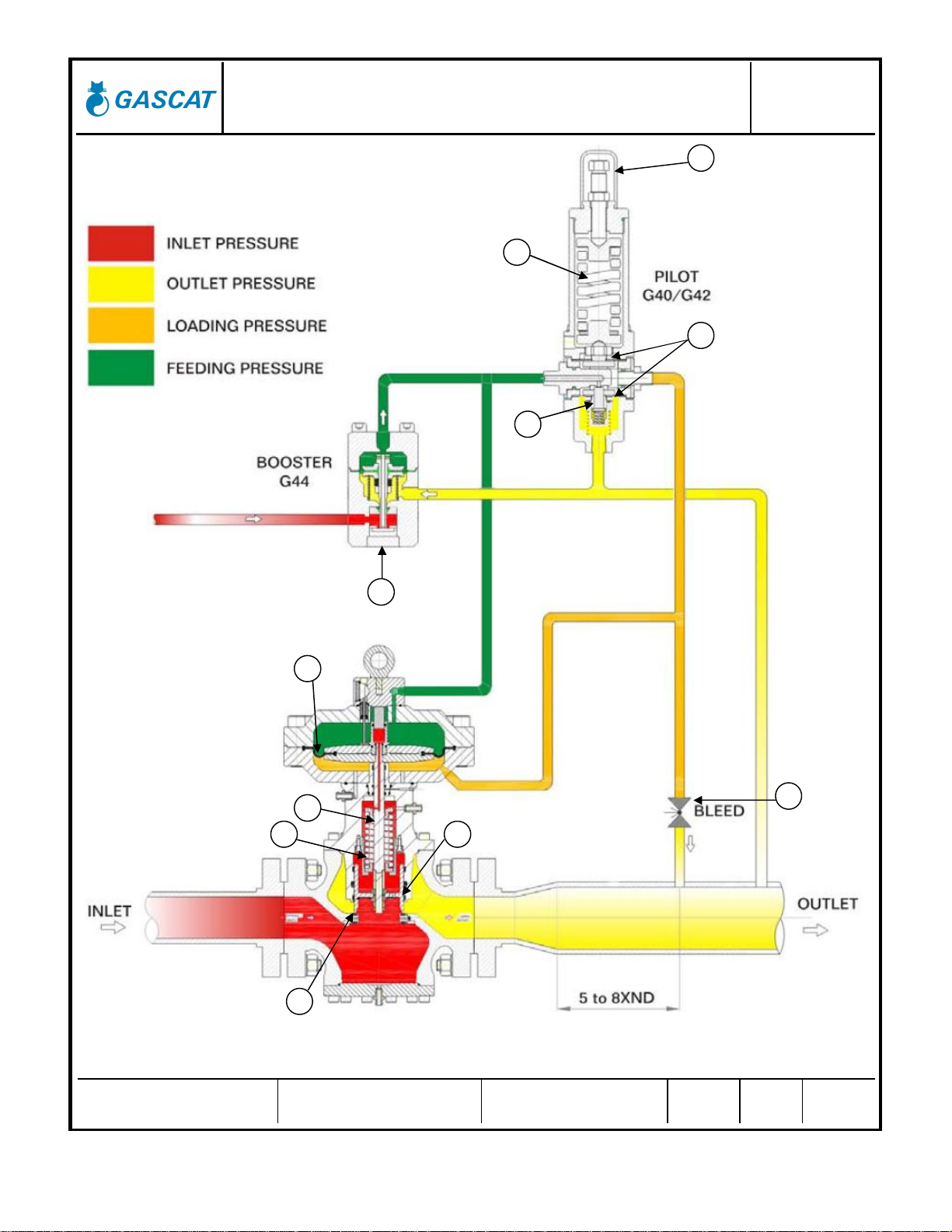
3.1 REGULATOR SPRING TO CLOSE (FAIL CLOSE)
During pressure absence, shutter (A) is kept in closed position by the shutting spring (B), which keeps it pressed
against the soft seat (C). It stands out that even when subject to pressure, upstream pressure variations have no influence
on the shutter position, due to the balancing of the forces acting on the same, as well as on the actuator shaft (D) that is
also balanced.
When the inlet piping is pressurized, gas passes through the filter element (E) and reaches the booster (F),
which reduces the pressure to a convenient value near to the outlet pressure and delivers the same to pilot (G).
The pilot compares the gas feeding pressure with the outlet pressure, sensed by the pilot diaphragm (H), and
controls the flow to be injected under the main regulator diaphragm (L).
If a decrease in downstream pressure occurs (due to an increased consumption or a drop of the upstream
pressure) an imbalance between the spring (I) force on the pilot (H) diaphragm and the force generated by the
outlet pressure under this same diaphragm, drives the pilot (K) shutter to a larger aperture, therefore, causing a
pressure increase under the main regulator (L) diaphragm, which combined with downstream pressure drop,
which actuates on the main regulator diaphragm and in the opposite side of the pilot pressure thereon, will
determines the displacement of the shutter (A) upwards, thereby increasing the passage and restoring the set
point.
When the pre-regulated pressure begins to increase, it makes the pilot (K) shutter to reduce the aperture. The
increased pressure, which actuated under the regulator (L) diaphragm, flows through the Bleed (M) restriction (adjustable)
that discharges the same downstream. The strength of the closing spring of the main regulator (B) plus the decrease of the
pilot pressure cause a downward displacement of the main shutter (A), making the pressure to return to the preset value.

Installation and Operation Manual
Urano - Pressure Regulating Valve MI-31
Elaborado Verificado / Aprovado CSQ Data Revisão Página
JJ JJ JM 05/07/21 05 10 de 74
FIGURE 1 - URANO FAIL CLOSE
A
B
D
C
E
F
G
H
L
I
K
M
Installation and Operation Manual
Urano - Pressure Regulating Valve MI-31
Elaborado Verificado / Aprovado CSQ Data Revisão Página
JJ JJ JM 05/07/21 05 11 de 74
3.2 REGULATOR SPRING TO OPEN (FAIL OPEN)
During pressure absence, shutter (A) is kept in the open position by the main regulator (B) spring, which keeps it away
from the gasket (C). It stands out that even when subject to pressure, upstream pressure variations have no influence on
the shutter position, due to the balancing of the forces acting on the same, as well as on the actuator shaft (D) that is also
balanced.
When the inlet piping is pressurized, gas passes through the filter element and reaches the pre-regulator (booster) (F), which
reduces the pressure to a convenient value near to the outlet pressure value and delivers the same to pilot (G). It is important to note
that unlike to the URANO FAIL CLOSE regulator, the pressure provided by the booster is injected also directly in the diaphragm upper
chamber. This is necessary for the regulator to close under normal operating conditions, since the main regulator spring is pressing the
shutter for it to stay in the open position.
The pilot compares the output pressure sensed by the diaphragm (H) and controls the flow to be injected under the
main regulator (L) diaphragm to open the valve.
If a decrease in the downstream pressure occurs (due to an increased consumption or a drop of the upstream pressure)
an imbalance between the spring (I) force on the pilot diaphragm (H) and the force generated by the outlet pressure under
this same diaphragm, drives the pilot (K) shutter to a larger aperture, therefore, causing a pressure increase under the
main regulator (L) diaphragm, determining the displacement of the shutter (A) upwards, thereby increasing the passage
and restoring the set point pressure.
When the setup pressure begins to increase, it requires the pilot (K) shutter to reduce the aperture. The higher pressure
that operated under the regulator (G) diaphragm flows through the Bleed (M) restriction (adjustable) that discharges the
same downstream, thereby causing the pressure to actuate on the diaphragm to be larger than the combined pilot force
and spring force, moving the shutter down and shutting the main valve.
Installation and Operation Manual
Urano - Pressure Regulating Valve MI-31
Elaborado Verificado / Aprovado CSQ Data Revisão Página
JJ JJ JM 05/07/21 05 12 de 74
FIGURE 2 - URANO FAIL OPEN
A
B
D
C
L
F
K
I
G
H
M

Installation and Operation Manual
Urano - Pressure Regulating Valve MI-31
Elaborado Verificado / Aprovado CSQ Data Revisão Página
JJ JJ JM 05/07/21 05 13 de 74
3.3 BOOSTER (G-43 & G-44)
The Booster is nothing more than a pre-regulator that automatically adjusts the process conditions as a
function of the input pressure and output pressure with the purpose of reducing the pilot inlet pressure, allowing
the pilot to operate in a milder condition, thus eliminating any chance of interference on the regulator piloting by
the input pressure variation.
The use of a pre-regulator, or booster, is recommended only for applications where the pressure differential
exceeds 4.0 bar.
Booster models G-43 and G-44 are designed to keep the pilot input pressure set 1 to 2 bar above the
desired set point, e.g.: if we are adjusting the pressure regulator to 20 bar, the booster will be applying to the
pilot a pressure of 21 to 22 bar.
Booster models G-43 and G-44 have a similar operation principle, although bearing construction
differences, with different internal parts. This differentiation is necessary for one to be able to operate FA
pressure control valves and the other for use with FF regulators. With pressure regulator valves model Urano,
pre-regulators model G-43 are used in the assemblies with valves FF and G-44 in assemblies with FA valves.
Typically, boosters G-43 & G-44 have three connections to the process. These are represented by the red
line in the figure above, from the regulator inlet and loaded with the inlet pressure; the yellow line is the output
pressure of the main regulator, also called sensor pick-up, and is responsible for actuating on the booster
diaphragm (A), moving the shaft (B) away from the gasket (C), thus allowing the passage of gas from the
regulator input at a pressure 1 to 2 Kgf/cm² above the set point pressure of the main regulator, which by its turn
is represented by the green color and is the pick-up that will follow to the Pilot.
Attention: In some assemblies, the booster can be integrated into the pilot; this change is merely ergonomic
to reduce space, component count and ease of operation. However, it is important to note that the operating
principle is exactly the same as given above.

Installation and Operation Manual
Urano - Pressure Regulating Valve MI-31
Elaborado Verificado / Aprovado CSQ Data Revisão Página
JJ JJ JM 05/07/21 05 14 de 74
3.4 PILOTS (G-40 & G-42)
The dual diaphragm pilot series G-40 and G-42 can achieve much higher regulation accuracies than other
pilots due to their construction characteristics.
Pilots are responsible for sending the exact loading pressure for pressure regulating valves to open or close
under normal process conditions by the balance between the regulation spring force and the outlet pressure
from the sensor pick-up.
The green line represents the pressure from the booster or pre-regulator, the yellow line is the regulator
output pressure (sensor pick-up) and is responsible for displacing the diaphragm assembly (A) up or down,
causing the pilot shutter (B) to leave the seat (C) thus allowing the inlet pressure reduction and sending the gas
at an appropriate pressure to load the main valve causing the valve to open or close according to the process
conditions.
3.5 FILTERS
The GASCAT pilot blocks, consisting of a pilot and pre-regulator always have a mechanical barrier against
solid impurities; this barrier comprises a polypropylene filter element of 10-micra filtration grade.
This barrier is intended to prevent that solid contaminants contained within the pipework can clog or damage
the internal parts of pre-regulator and of the pilot. However, it is important to note that this filter does not
replace the filtration system that shall be provided in preliminary steps to pressure regulating to leave
the fluid clean and according to correct operating conditions. This filter is designed to serve as the last
barrier to solid contaminants.
A
B
C

Installation and Operation Manual
Urano - Pressure Regulating Valve MI-31
Elaborado Verificado / Aprovado CSQ Data Revisão Página
JJ JJ JM 05/07/21 05 15 de 74
The Urano pressure regulators can be provided with an F-10 filter mounted in separate from the pilot unit, or
in a compact version, with the filter element already coupled to the pre-regulator.
3.6 SECURITY SHUT-OFF VALVE
3.6.1 ACTUATOR PH & H ACTUATOR
The slam shut valve has two actuators models, one with a diaphragm (for pressures 1.0 – 11.0 bar) and other with a
piston (for pressures 10.0 – 60.0 bar).
Mechanism consists in a shaft (stem) and spheres collar monitoring the outlet pressure. In case of outlet pressure
increase or decrease, the external bush will move up or move down, allowing the spheres running out of channel and the
main shaft moves according to the force exerted by closing spring to close the valve against the seat, shutting downs the
gas totally tight (see the picture with the two conditions).
After reestablishing to the normal service condition operation it is necessary to reset manually the slam shut valve.
-Position 1: Shutting by increase pressure
-Position 2: Balanced mechanism
-Position 3: Shutting by decrease pressure
3.6.2 – GENERAL RESET PROCEDURE
To reset the valve to the open position (ready to work), the sensing line should be connected in the actuator
chamber .
Position 1
Position 2
Position 3
Installation and Operation Manual
Urano - Pressure Regulating Valve MI-31
Elaborado Verificado / Aprovado CSQ Data Revisão Página
JJ JJ JM 05/07/21 05 16 de 74
3.6.2.1 – PROCEDURE TO RESET VALVE IN CASE OF OVER PRESSURE
1. Adjust the pressure of sensing line around 10-15% below under the set-point.
2. Use the by-pass valve to equalize the internal pressure of the valve.
3. Pull up the actuator stem until the upper position using the cap.
3.6.2.2 – PROCEDURE TO RESET VALVE IN CASE OF UNDER PRESSURE
1. Adjust the pressure of sensing line around 10-15% above the over set-point.
2. Use the by-pass valve to equalize the internal pressure of the valve.
3. Pull up the actuator stem until the upper position using the cap
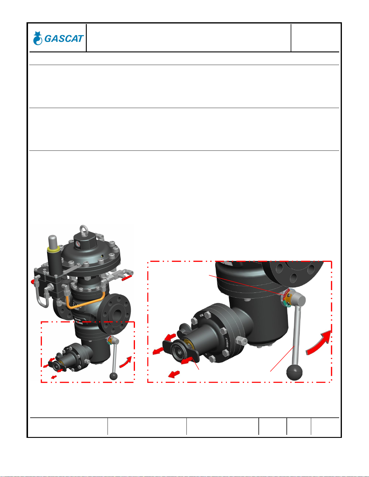
3.6.3 – SHUT-OFF RESET & INTEGRATED BYPASS PROCEDURE
To reset the shut-off, it is necessary to equalize the pressure before and after the shutter. However it is
necessary to use the integrated bypass in the reset lever. See below how to proceed:
When there is a lock, the position indicator will be indicated in closed position (according the picture). Then
it is necessary to use the cap screwing it to pull up the shaft (according the picture). After connecting the cap in
the actuator stem, the user should pull up the cap and to move the reset lever at the same time (according the
picture). The reset lever will move 20% of course, there is a resistance (because the differential pressure
between the inlet pressure and the outlet pressure) until the pressure before and after the shutter to be the
same.
The SSV is supplied in the closed position and with the actuator of under pressure blocking disarmed. The
springs for over and under pressure blocking are adjusted in Gascat.
Position Indicator
(closed position)
Reset
L
ever
Cap
Fi
gure 1
Figure
2
Installation and Operation Manual
Urano - Pressure Regulating Valve MI-31
Elaborado Verificado / Aprovado CSQ Data Revisão Página
JJ JJ JM 05/07/21 05 17 de 74
3.7 ACTIVE MONITOR ASSEMBLY
The so-called active monitor installation configuration is largely used in natural gas distribution and
transmission. This configuration is usually adopted when the difference between the inlet pressure and the
outlet pressure is greater than 16 bar and the downstream piping stress test pressure, and the stress pressure
of the other components downstream of the regulator is smaller than the specified inlet pressure, for example,
as given in DIN EN 12186. In this case, the objective of the monitor regulator use is to increase the safety level
of the station.
However, it is worth remembering that this is the recommendation of the DIN EN 12186 Standard, but other
standards specify different conditions for using the active monitor system.
The active monitor system uses two pressure regulators in series, with one of them called active, which will
be in operation (regulating) under normal processing conditions and shall be of the SO (FA) type, and the other,
an SC (FF) monitor, shall remain fully open during normal operation and will only assume regulation in case of
the active regulator failure.
As already mentioned in this manual, is important to bear in mind that the classification as FA or FF is given
exclusively by the main valve diaphragm fail, and lack of power for the shutter operation, according to DIN EN
334, however, it is quite possible that the regulator FA, for example, fails closed due to some other condition
unforeseen in the process. See below some fail positions of regulators URANO SC and URANO OS as a
function of possible situations in the field:
SITUATION
URANO SC (FF)
URANO SO (FA)
FAIL
OPEN
FAIL
CLOSED
FAIL
OPEN
FAIL
CLOSED
MAIN VALVE DIAPHRAGM FAILURE X X
PILOT DIAPHRAGM FAILURE X X
DIRT BETWEEN THE SHUTTER AND THE
MAIN VALVE SEAT X X
DIRT BETWEEN THE SHUTTER AND THE
PILOT SEAT X X
MAIN SHAFT LOCKED X X X X
SENSOR PICK-UP BREACH X X
OBSTRUCTION OF THE PILOT SEAT X X
BOOSTER DIAPHRAGM FAILURE X X
URANO regulators operate in the active monitor system exactly as described in items 3.1 and 3.2 of this
manual, but as can be seen in the previous scheme the sensor pick-up of the SC (FF) controller is downstream
of the active regulator SO (FA) and its set point must be adjusted to a slightly higher pressure than the set point
of the active regulator (5%-10% depending on the application).
Therefore, during normal operation conditions, the monitor regulator will be completely open while the active
regulator is in operation. If any fail occurs in the active regulator, and pressure starts to increase, the monitor
regulator will start to operate.

Installation and Operation Manual
Urano - Pressure Regulating Valve MI-31
Elaborado Verificado / Aprovado CSQ Data Revisão Página
JJ JJ JM 05/07/21 05 18 de 74
A
C
T
I
V
E
M
O
N
I
T
O
R
A
S
S
E
M
B
L
Y

Installation and Operation Manual
Urano - Pressure Regulating Valve MI-31
Elaborado Verificado / Aprovado CSQ Data Revisão Página
JJ JJ JM 05/07/21 05 19 de 74
4.0 - INSTALLATION
4.1 FILTER
We recommend the installation of a cartridge type filter, with 5 micra filtration degree, as close to the regulator inlet as
possible, without being joined flange to flange, because the filter installed immediately upstream of the regulator may
produce turbulence and cause disturbance in the pressure control of the regulator. Care in filter installation is essential for
the regulator proper operation, as any existing particles in the pipe may take lodge between the seat and the shutter,
damaging them and causing feedthrough.
4.2 CLEANING
Check the pipe cleaning before valve installation. We advise a complete purge of the line with nitrogen or compressed air.
4.3 FLOW DIRECTION AND SYSTEM INTEGRITY
Before starting the equipment installation, it is necessary to check if:
1) The equipment is in perfect conditions, or it has evidence of damage during transportation. If so, do not proceed
with the installation and contact GASCAT.
2) The space provided for access and installation of the equipment is adequate for future maintenance.
3) The installation is designed to support the load applied by the equipment.
4) The inlet and outlet connections, where the pressure regulator shall be installed, are perfectly aligned.
5) All necessary pressure-sensing pick-ups, downstream of the equipment pipeline, were provided respecting the
dimensions recommended by the manufacturer.
6) A pressure gauge, or any other pressure-measuring device, was foreseen for the upstream and downstream of the
equipment to allow for the correct setting up at the operation start-up.
7) A vent line was planned between the regulator and thefirst outlet shut-off valve to assist the operator during start-up.
8) Check the flow direction marked on the body of the pressure-regulating valve and pay attention at the time of its
installation so that it is properly positioned.
Installation and Operation Manual
Urano - Pressure Regulating Valve MI-31
Elaborado Verificado / Aprovado CSQ Data Revisão Página
JJ JJ JM 05/07/21 05 20 de 74
4.4 IMPULSE PICK-UP
The correct positioning of the impulse pick-up in the pipeline is essential for proper operation of the pressure
regulator valve. Therefore, install the pilot impulse pick-up downstream of the regulator at a minimum distance of 5
times the nominal pipe diameter, in a pipe span free of obstruction with a pipe diameter where the gas outflow does
not exceed the maximum speed of 25 m/s (considering the smallest outlet pressure and the maximum flow rate).
To obtain a better pneumatic signal use tubing in stainless steel AISI 316 with ½" OD to connect the regulator pick-
ups to the process.
To prevent dirt and condensates accumulation in impulse pick-ups, we recommend that their installation shall have
a 5% to 10% slope towards the pipe connector.
Pay attention to connections welded to the pipe, they must be fully unobstructed, without any welding residue that
can interfere with the pneumatic signal.
No kind of blocking valves shall be installed in pressure regulators impulse outlets.
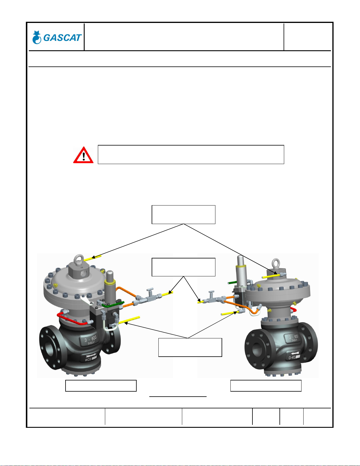
Each pressure regulator model Urano SC (FF) needs three process connections: one directly to the actuator on the
diaphragm, one that will be connected directly below the pilot and a third one that will be used to unload the actuator
under the diaphragm.
IMAGE OF URANO FF
It is not must be installed blocking valves in any types in the sense line.
DISCHARGE OUTLET
PILOTSENSOR
OUTLET
VALVE
SENSOROUTLET
FRONT VIEW
BACK VIEW
Other manuals for URANO FA
1
This manual suits for next models
1
Table of contents
Other Gascat Control Unit manuals


Popular Control Unit manuals by other brands

Fisher
Fisher Control-Disk instruction manual

Giacomini
Giacomini R701F instruction manual

schmersal
schmersal PROTECT-IE Series operating instructions

KUHN
KUHN Hector 3000 Complementary instructions

Zehnder Pumpen
Zehnder Pumpen ENS 1.1 operating manual

VALSTEAM ADCA
VALSTEAM ADCA TSS 7 Installation and maintenance instructions

Lovato
Lovato GEX69 C Series manual

GF
GF DSR 500-1 operating instructions

Sobek drives
Sobek drives KONTRONIK Operation manual

Genius
Genius GE-V1 Installation & user guide

ARAG
ARAG 8537 Series Installation, use and maintenance

Heritage Bathrooms
Heritage Bathrooms SDC04 Installation instructions and user guide


