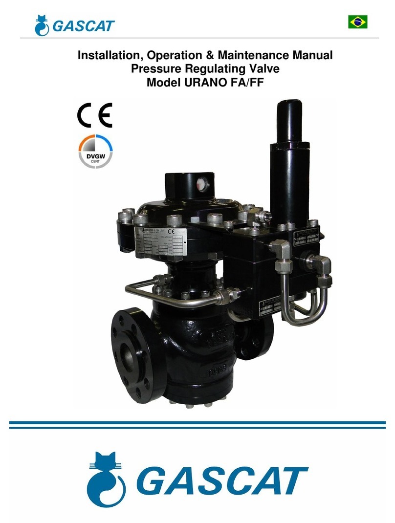
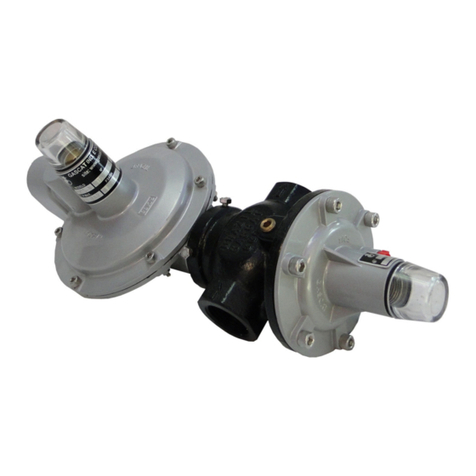
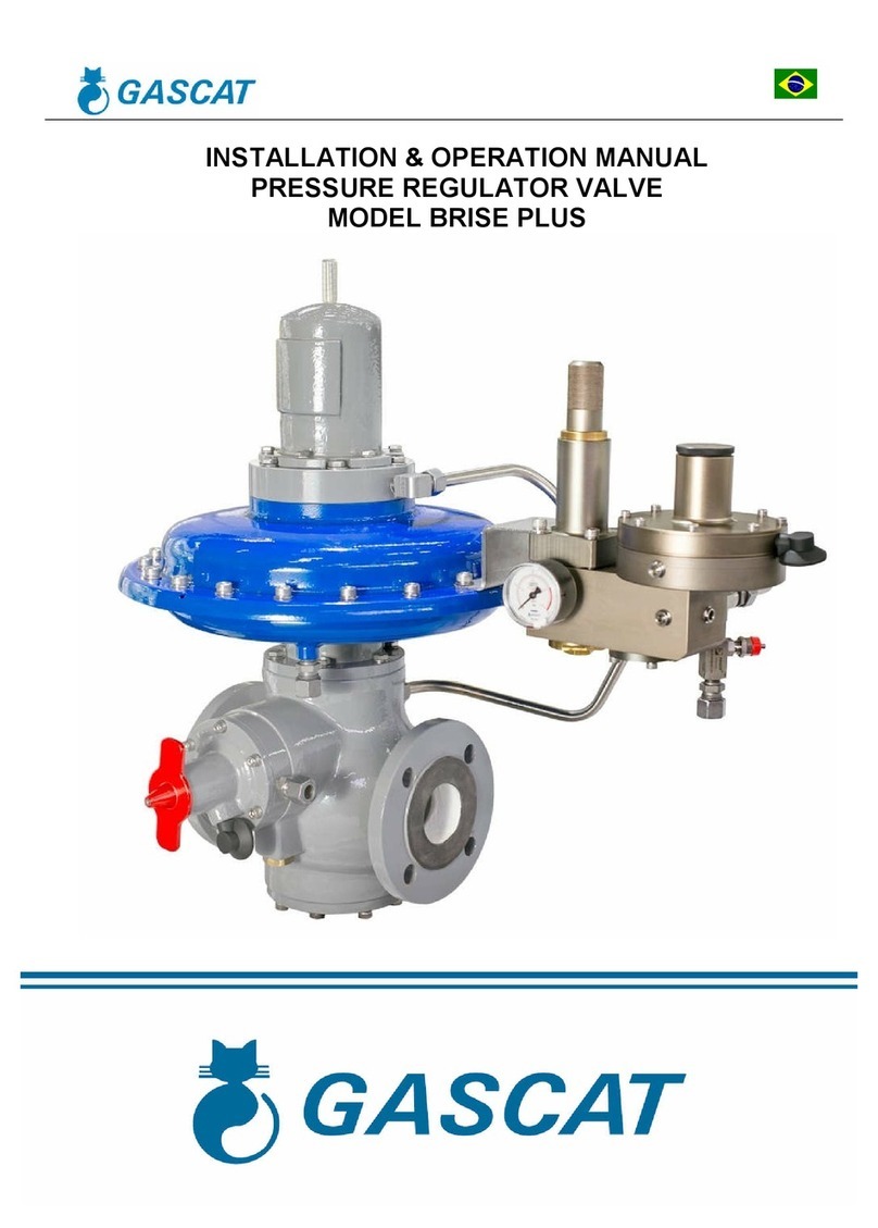
Gascat URANO FA User guide

Installation Manual, Maintenance and Operation
Pressure Regulating Valve
Installation Manual, Maintenance and Operation
Pressure Regulating Valve
Model URANO FA/FF
Installation Manual, Maintenance and Operation

Installation Manual, Maintenance and Operation
Pressure Regulating Valve – Model Urano
MI-31
Elaborate Verified / Approved CSQ Date Review Page
Raphael Pereira Vanízio Lizo Gustavo Nieto
05/06/14
04 2 de 61
INDEX
1.0 - GENERAL WARNINGS .......................................................................................................................................................... 4
1.1
–
INSTRUCTIONS
FOR
COMMISSIONING .................................................................................................................................... 4
1.2
–
HEALTH
AND
SAFETY ............................................................................................................................................................... 4
1.2.1 – NOISE ............................................................................................................................................................................... 4
1.2.2 – INSTALLATION ................................................................................................................................................................. 4
1.2.3 – OPERATION ...................................................................................................................................................................... 4
1.2.4 – MAINTENANCE ................................................................................................................................................................ 5
2.0 – INTRODUCTION ................................................................................................................................................................... 5
2.1
SCOPE
OF
MANUAL .................................................................................................................................................................... 5
2.2
DESCRIPTION .............................................................................................................................................................................. 5
2.3
SPECIFICATIONS ......................................................................................................................................................................... 6
2.3.1 AVAILABLE SETTINGS .......................................................................................................................................................... 6
2.3.2 AVAILABLE CONNECTIONS.................................................................................................................................................. 6
2.3.3 TEMPERATURE LIMITS ........................................................................................................................................................ 6
2.3.4 COEFFICIENTS FLOW ........................................................................................................................................................... 6
2.3.5 APPROXIMATE WEIGHT ...................................................................................................................................................... 7
2.3.6 MAXIMUM WORKING PRESSURE ...................................................................................................................................... 7
2.3.7 SETTING PRESSURES SET-POINT) ....................................................................................................................................... 7
2.3.8 ACCURACY AND LOCK UP ................................................................................................................................................... 8
3.0 – PRINCIPLE OF OPERATION ................................................................................................................................................... 8
3.1
REGULATOR
SPRING
TO
CLOSE
(FAIL
CLOSE) .............................................................................................................................. 8
3.2
REGULATOR
SPRING
TO
OPEN
(FAIL
OPEN) .............................................................................................................................. 10
3.3
OOSTER
(G-43
&
G-44) ........................................................................................................................................................... 12
3.4
PILOTS
(G-40
&
G-42) ............................................................................................................................................................... 13
3.5
FILTERS ..................................................................................................................................................................................... 14
3.6
MOUNT
MONITOR
AND
ACTIVE ............................................................................................................................................... 14
4.0 – INSTALLATION ................................................................................................................................................................... 15
4.1
FILTER ....................................................................................................................................................................................... 15
4.2
CLEANING ................................................................................................................................................................................. 16
4.3
DIRECTION
OF
FLOW
AND
SYSTEM
INTEGRITY ......................................................................................................................... 16
4.4
SENSE ....................................................................................................................................................................................... 17
4.5
SCHEME
RECOMMENDED
INSTALLATION ................................................................................................................................ 19
4.5.1 SINGLE REGULATOR ......................................................................................................................................................... 19
4.5.2 SISTEM MONITOR AND ACTIVE ........................................................................................................................................ 21
4.5.3 TWO SSV AND A REGULATOR FF ...................................................................................................................................... 23
4.6
START-UP ................................................................................................................................................................................. 25
4.6.1 GENERAL RECOMMENDATIONS ....................................................................................................................................... 25
4.6.2 COMMISSIONING SINGLE REGULATOR) ......................................................................................................................... 26
4.6.3 ADJUSTING THE LINE BOOKING ........................................................................................................................................ 27
4.6.4 COMMISSIONING SISTEM MONITOR AND ACTIVE)......................................................................................................... 28
4.6.5 ADJUSTING THE LINE BOOKING MONITOR - ACTIVE) ...................................................................................................... 31
4.6.6 LIST OF RECOMMENDED TOOLS ....................................................................................................................................... 32
5.0 TROUBLE SHOOTING ............................................................................................................................................................ 33
6.0 MAINTENANCE .................................................................................................................................................................... 34
6.1
RECOMMENDED
REPAIR
PARTS
AND
KITS ............................................................................................................................... 35
6.2
PROCEDURE
FOR
REMOVAL
THE
REGULATOR
URANO
SC
(FF) ................................................................................................ 43
6.3
PROCEDURE
FOR
ASSEM LY
REGULATOR
URANO
SC
(FF) ....................................................................................................... 45
6.4
PROCEDURE
FOR
REMOVAL
THE
REGULATOR
URANO
SO
(FO) ................................................................................................ 46

Installation Manual, Maintenance and Operation
Pressure Regulating Valve – Model Urano
MI-31
Elaborate Verified / Approved CSQ Date Review Page
Raphael Pereira Vanízio Lizo Gustavo Nieto
05/06/14
04 3 de 61
6.5
PROCEDURE
FOR
ASSEM LY
REGULATOR
URANO
SO
(FO) ...................................................................................................... 50
6.6
PROCEDURE
FOR
REMOVAL
THE
PILOT
G-40
/
42 .................................................................................................................... 50
6.7
PROCEDURE
FOR
ASSEM LY
THE
PILOT
G-40
/
42 .................................................................................................................... 53
6.8
PROCEDURE
FOR
REMOVAL
OOSTER
(PRE-EGULATOR)
G-43 ................................................................................................ 54
6.9
PROCEDURE
FOR
ASSEM LY
OOSTER
(PRÉ
REGULATOR)
G-43 .............................................................................................. 57
6.10
PROCEDURE
FOR
REMOVAL
OOSTER
(PRE-REGULADOR)
G-44 ................................................. E
RRO
I
NDICADOR NÃO DEFINIDO
.
6.11
PROCEDURE
FOR
ASSEM LY
OOSTER
(PRE-REGULADOR)
G-44 ........................................................................................... 60
6.12
LIST
OF
RECOMMENDED
TOOLS
FOR
MAINTENANCE .................................................................. E
RRO
I
NDICADOR NÃO DEFINIDO
.

Installation Manual, Maintenance and Operation
Pressure Regulating Valve – Model Urano
MI-31
Elaborate Verified / Approved CSQ Date Review Page
Raphael Pereira Vanízio Lizo Gustavo Nieto
05/06/14
04 4 de 61
1.0 - GENERAL WARNINGS
1.1 – INSTRUCTIONS FOR PRE COMMISSIONING
It should be clearly understood that with the information presented in Commissioning Instructions that follow, it is not
intended to repeal or replace the instructions determined by any other competent body and should be reference to the
relevant standards and / or existing recommendations on this subject.
Before any commissioning, is implied the performance of the appropriate "Cleaning and Purification Procedures" that
must be observed and all the instructions on "Pressurization" and "Work Standards for Health and Safety", must be strictly
met.
The recommendations of valves suppliers, such as "open slowly" or "open very slowly" should be strictly observed.
1.2 – HEALTH AND SAFETY
Regulators, valves, and other pressurized components that contain toxic gases, flammable or other hazardous
products, are potentially dangerous if not operated and maintained properly. It is imperative that all users of this equipment
are adequately educated and guided to the potential hazards and make sure that staff responsible for the installation,
testing, commissioning, operation and plant maintenance are competent to do this. Instruction manuals are provided for the
guidance of operators, but it is assumed that they have a basic level of knowledge. If any doubts or ambiguities that affect
the proper procedures ask Gascat Ind e Com. Ltda. who will be happy to advise or provide the relevant service or
instruction. NO RISK. Our phone number, fax number and e-mail are described below:
Gascat Indústria e Comércio Ltda.
Rodovia SP 73, 1141 – Indaiatuba / São Paulo.
CEP 13347-990
Telefone: +55 19 3936-9300
Fax: +55 19 3935-6009
Email:
[email protected]om.br
The comments that follow, while not exhaustive, provide guidance possible sources of danger to health and safety.
1.2.1 – NOISE
Regulators, valves and pressure reducers can produce high noise levels, which may be harmful to persons exposed to
them for long periods of time. Users should ensure that adequate precautions are taken in order to provide security to the
health of employees and / or third parties as the standards and recommendations in force.
1.2.2 – INSTALLATION
All equipment, piping and vessels are designed to withstand mechanical stress, for example, torque and moments of
"bending" in addition to internal pressure. However, care must be taken during installation to not impose excessive strain,
which may cause cracks that may result in a more serious break when the regulator is put into operation. Excessive stress
can also be caused due to not supporting the length of the pipe, which must be adequately supported.
All regulators, valves shut off, relief valves, etc., should be installed with the correct flow.
Impulse lines are important components of any control system and it is essential that they are properly installed and
without isolation valves.
Impulse lines should be adequately supported to reduce excessive vibration which may cause disruption due to fatigue.
They should also be positioned so that they can not serve as a footrest or hands. Impulse lines should be slightly inclined
so that condensed liquids and to flow into the main pipe.
When necessary (in underground facilities or indoor area) should be installed a pipe ventilation from Ø threaded ¼
"NPT, positioned in the bell or diaphragm housing, which should be extended and positioned in a safe place and ventilated,
with the departure of protected vent to prevent water entering the rain and insects that may cause obstruction of ventilation.
Auxiliary systems should not be altered or modified without the knowledge of operating conditions and permission of the
people responsible.

Installation Manual, Maintenance and Operation
Pressure Regulating Valve – Model Urano
MI-31
Elaborate Verified / Approved CSQ Date Review Page
Raphael Pereira Vanízio Lizo Gustavo Nieto
05/06/14
04 5 de 61
1.2.3 – OPERATION
Depending on the type of regulator, the valve may even be positioned fully open. Consequently, when a regulator put in
operation, the shutoff valves should be opened slowly so that the regulator valve can assume its regulating position. If the
valves are quickly opened the upstream pressure can pass downstream through the regulator and over-pressurize
downstream the main line.
All regulators, etc., should operate with the spring adjustment specified by the manufacturer. This is especially important
when operating relief valve or shutoff valves, since incorrect springs may prevent the relief valve to open and close the
shutoff valve.
Precautions should be taken to prevent water from entering through the openings for breathing and ventilation.
1.2.4 – MAINTENANCE
Regulators and valves contain gases at pressures that are sometimes greater than atmospheric pressure. Before trying
to investigate any problem or perform maintenance work on equipment, they must be safely depressurised. Furthermore,
as most gases may be flammable, toxic, corrosive, or hazardous, it may be necessary to purge the system with an inert
gas such as nitrogen. Special precautions are necessary for operation with gases such as oxygen or hydrochloric gas and
the user must be sure that the appropriate procedures are in place.
Eventually it is not enough to isolate the high pressure device, since high pressures can be retained downstream of
isolation valves. Do not try to remove covers, plugs, etc., before this device is properly released. Still, it is wise to consider
that the high pressure gas may be present when removing covers and plugs.
Most regulators use spiral springs as a charging device. It is important to reduce the burden these springs away your
presser as possible. In some cases, there may be some cargo residue, even when the spring is relaxed within the limits of
their house.
2.0 – INTRODUCTION
2.1 SCOPE OF MANUAL
This manual aims to provide operational information, installation and maintenance of the pressure regulators URANO
model manufactured by GASCAT.
2.2 DESCRIPTION
The pilot operated pressure regulator model URANO was developed by the Engineering GASCAT, to meet the most
varied applications and can operate in various operating conditions, however, it is particularly applicable in situations where
requires high flow rates associated with high pressures, typically found in natural gas transportation and custody transfer in
natural gas delivery point and can operate with a maximum inlet pressure of 150 kgf/cm² and outlet pressures from 1.0 to
80.0 kgf/cm².
The pressure regulator of URANO GASCAT model has CE mark (product identification Number: CE-0085BU0263) and
certified tests performed in the laboratory DVGW attesting its efficiency and compliance with DIN EN 334 (Gas pressure
regulators for inlet pressures up to 100 bar) and 97/23 / EG (PED), the DVGW certificates and reports are available for
inspection at GASCAT if some of the documents necessary for your application, please contact our Headquarters in
Indaiatuba and request copies of these documents.

Installation Manual, Maintenance and Operation
Pressure Regulating Valve – Model Urano
MI-31
Elaborate Verified / Approved CSQ Date Review Page
Raphael Pereira Vanízio Lizo Gustavo Nieto
05/06/14
04 6 de 61
2.3 SPECIFICATIONS
2.3.1 AVAILABLE SETTINGS
URANO FA: Pilot operated pressure regulator fail open
URANO FF: Pilot operated pressure regulator failure close
The URANO pressure regulators are classified as FA and FF according to the guidelines reported in DIN EN 334, for fault
condition
2.3.2 AVAILABLE CONNECTIONS
DN FLANGE ASME B16.5 FLANGE DIN 2634 / 2635
1” 150#RF / 300#RF / 600#RF ou RTJ / 900#RF ou RTJ PN 25 / PN 40
2” 150#RF / 300#RF / 600#RF ou RTJ / 900#RF ou RTJ PN 25 / PN 40
3” 150#RF / 300#RF / 600#RF ou RTJ / 900#RF ou RTJ PN 25 / PN 40
4” 150#RF / 300#RF / 600#RF ou RTJ / 900#RF ou RTJ PN 25 / PN 40
6” 150#RF / 300#RF / 600#RF ou RTJ / 900#RF ou RTJ PN 25 / PN 40
8” 150#RF / 300#RF / 600#RF ou RTJ / 900#RF ou RTJ PN 25 / PN 40
2.3.3 TEMPERATURE LIMITS
Operating temperature: -20°C a 60°C
Ambient temperature: -20°C a 60°C
Temperature limits reported in this manual or any standard should not be exceeded under any circumstances, at the
risk of damage to the equipment, installation and security of the people involved in the operation.
2.3.4 COEFFICIENTS FLOW
DN CV KG
1” 15 440
2” 63 1950
3” 123 3800
4” 220 6850
6” 486 15080
8” 900 28250
Note:
1) We suggest that is considered a 20% safety factor on the calculated value.
2) When scaled active-monitor system finds 25% restriction on the CV / KG of both valves.

Installation Manual, Maintenance and Operation
Pressure Regulating Valve – Model Urano
MI-31
Elaborate Verified / Approved CSQ Date Review Page
Raphael Pereira Vanízio Lizo Gustavo Nieto
05/06/14
04 7 de 61
2.3.5 APPROXIMATE WEIGHT
DN 150# 300# 600# 900#
1” 24 26 30 34
2” 95 100 112 128
3” 99 105 130 149
4” 185 195 215 247
6” 475 500 570 655
8” 570 600 690 793
Note:
1) Weights reported in kilograms (Kg)
2) Considered body in carbon steel SA-216 WCB
3) For the exact weights contact the GASCAT for verification of the model.
2.3.6 MAXIMUM WOR ING PRESSURE
150# 300# 600# 900# PN 25 PN 40
19 bar 51 bar 100 bar 150 bar 25 bar 40 bar
Pressure limits reported in this manual or any standard should not be exceeded under any circumstances, at the risk of
damage to the equipment, installation and security of the people involved in the operation.
2.3.7 SET-POINT
Pressure regulators, model URANO using two models of pilots for pressure control called G-40 and G-42, here are the
adjustment ranges available for each model:
PILOT G-40
SPRING COLOR CODE ADJUSTMENT RANGE
RED 01.51.94A 25,0 – 50,0 bar
YELLOW 01.51.94 47,0 – 80,0 bar
PILOT G-42
SPRING COLOR CODE ADJUSTMENT RANGE
GREEN 01.49.65 1,0 – 4,5 bar
GRAY 01.49.64 4,5 – 12,0 bar
BLUE 01.49.33 11,0 – 17,0 bar
RED 01.51.94A 16,0 – 30,0 bar
YELLOW 01.51.94 27,0 – 55,0 bar

Installation Manual, Maintenance and Operation
Pressure Regulating Valve – Model Urano
MI-31
Elaborate Verified / Approved CSQ Date Review Page
Raphael Pereira Vanízio Lizo Gustavo Nieto
05/06/14
04 8 de 61
2.3.8 ACCURACY AND LOC UP
Accuracy; Closing: AC até 1; SG até 2,5
3.0 – PRINCIPLE OF OPERATION
3.1 REGULATOR SPRING TO CLOSE (FF)
In the absence of pressure, the obturator (A) is kept in closing position by the closing spring (B) which keeps the gasket
pressed against (C). Importantly, even when subjected to pressure the variation of pressure upstream will have no
influence on the setting of the valve due to the balancing of the forces acting on it, as well as the actuator shaft (D) which is
also balanced.
By pressurizing the leg, the gas passes through a filter element (E) reaches a pre controller (booster) (F) reduces to a
near value of the output pressure and delivering the pilot (G) as compared to the output pressure sensed by the pilot
diaphragm (M), which controls the flow is injected under the main regulator diaphragm (L).
If a decrease in the downstream pressure (for consumption or increasing the amount of pressure drop) occurs an
imbalance between the force of the spring (R) on the pilot diaphragm (M) and the force generated by the outlet pressure
under the same diaphragm, causing the shutter driver (K) to a larger aperture, causing an increase in pressure under the
main regulator diaphragm (L), which combined with downstream pressure drop which acts on the main regulator
diaphragm and opposite the pilot pressure acting on it, determine the displacement of the shutter (A) up, thereby
increasing the passage restoring the pressure (set point).
When the pressure begins to increase, causes the shutter driver (K) to reduce the opening. The increased pressure
which operated under the regulator diaphragm (L) flows through the restriction of Bleed (M) (adjustable) that discharges
into downstream. The strength of the main regulator of the closing spring (B) plus the reduction in pilot pressure causes
displacement of the main shutter (A) down, thus making the pressure back to the preset value.

Installation Manual, Maintenance and Operation
Pressure Regulating Valve – Model Urano
MI-31
Elaborate Verified / Approved CSQ Date Review Page
Raphael Pereira Vanízio Lizo Gustavo Nieto
05/06/14
04 9 de 61
FIGURE 1 - URANO FAIL CLOSED
A
D
C
E
F
G
H
L
I
K
M

Installation Manual, Maintenance and Operation
Pressure Regulating Valve – Model Urano
MI-31
Elaborate Verified / Approved CSQ Date Review Page
Raphael Pereira Vanízio Lizo Gustavo Nieto
05/06/14
04 10 de 61
3.2 REGULATOR SPRING TO OPEN (FA)
In the absence of pressure, the obturator (A) is in the open position by the main regulator spring (B) which keeps away
from the sleeve (C). Importantly, even when subjected to pressure the variation of pressure upstream will have no
influence on the setting of the valve due to the balancing of the forces acting on it, as well as the actuator shaft (D) which is
also balanced.
To pressurize the leg, the gas passes through a filter element and reaches the pre regulator (booster) (F) that reduces
to a value near the outlet pressure, and delivery to the pilot (G), it is important to note that unlike what happens in URANO
artifact closes regulator, the pressure provided by the booster is also injected directly into the upper chamber of the
diaphragm, it is necessary for the regulator to close at normal operating conditions, since the main regulator spring
pressing this the shutter so that it is in the open position.
The pilot compares the output pressure sensed by the diaphragm (M) and controls the flow that is injected under the
main regulator diaphragm (G) to open the valve.
If a decrease in the downstream pressure (for consumption or increasing the amount of pressure drop) occurs an
imbalance between the force of the spring (R) on the pilot diaphragm (M) and the force generated by the outlet pressure
under the same diaphragm, causing the shutter driver (K) to a larger aperture, causing an increase in pressure under the
main regulator diaphragm (L), determining the displacement of the shutter (A) up, thereby increasing the pressure restoring
passage (Sept -point).
When the pressure begins to increase, causes the shutter driver (K) to reduce the opening. Most operated under
pressure regulator diaphragm (L) flows through the restriction of Bleed (M) (variable) discharges into the downstream,
thereby causing the pressure acting on the diaphragm is greater than the driving force and the strength of the combined
spring, moving the shutter down and closing the main valve.

Installation Manual, Maintenance and Operation
Pressure Regulating Valve – Model Urano
MI-31
Elaborate Verified / Approved CSQ Date Review Page
Raphael Pereira Vanízio Lizo Gustavo Nieto
05/06/14
04 11 de 61
FIGURE 2 - URANO FAIL OPEN
A
D
C
L
F
K
I
G
H
M

Installation Manual, Maintenance and Operation
Pressure Regulating Valve – Model Urano
MI-31
Elaborate Verified / Approved CSQ Date Review Page
Raphael Pereira Vanízio Lizo Gustavo Nieto
05/06/14
04 12 de 61
3.3 BOOSTER (G-43 & G-44)
The Booster is nothing more than a pre regulator that automatically adjusts the process conditions depending on
input pressure and output, and aims to reduce the pilot inlet pressure, causing it to operate in a milder condition, thus
eliminating any chance of interference on the regulator pilot by the input pressure variation.
The use of pre regulators or booster is recommended only for applications where the differential pressure exceeds
4.0 bar.
The boosters G-43 and G-44 model are designed to keep the inlet pressure of the pilots always adjusted to 1-2 bar
above the set-point desired, eg if we are adjusting the throttle to 20 bar the booster will be sending for the rider a 21-22 bar
pressure.
The boosters G-43 and G-44 model have similar principle of operation, although they have constructive
differences, such as different internal, this differentiation is necessary for one to be able to operate with regulatory pressure
valve FA and the other regulators for use with FF, where the pressure regulator valve model G URANO pre-regulators are
used in model 43 assemblies with valves and FF G-44 in FA valve assemblies.
The boosters G-43 and G-44 normally have three connections to the process, represented in red line in the figure
above is from the regulator inlet and is loaded with the inlet pressure, the yellow line is the output pressure of the main
regulator also sensing called socket and is responsible for acting on the diaphragm (A) of the booster, moving the axis (B)
causing it to move away from the sleeve (C), thus allowing the passage of gas from the regulator input pressure 1 to 2
kgf/cm² above the set point pressure of the main regulator, which in turn is represented by the color green and is taken to
proceed to the Pilot.
Please note: In some assemblies the booster can be integrated into the pilot, this amendment is merely to reduce
ergonomic spaces, number of components and ease of operation, however it is important to note that the operating
principle is exactly the same as noted above.
A
C

Installation Manual, Maintenance and Operation
Pressure Regulating Valve – Model Urano
MI-31
Elaborate Verified / Approved CSQ Date Review Page
Raphael Pereira Vanízio Lizo Gustavo Nieto
05/06/14
04 13 de 61
3.4 PILOTS (G-40 & G-42)
The number of drivers G-40 and G-42 is comprised of dual diaphragm pilot that can achieve much higher precision
adjustment to other drivers due to their constructional characteristics.
Pilots are responsible for sending the exact loading pressure for pressure regulating valves open or close under normal
process conditions by the balance between the force of the regulating spring and the outlet pressure received by the
sensor outlet.
The green line represents the pressure from the booster or pre regulator, the yellow line is the regulator output
pressure (sensor outlet) and this is responsible for moving the diaphragm assembly (A) upward or downward, causing the
driver shutter (B) Move it headquarters (C) thus permitting the reduction in inlet pressure and sending the appropriate gas
pressure to perform charging of the main valve causing the valve to open or close according to the process conditions.
A
C

Installation Manual, Maintenance and Operation
Pressure Regulating Valve – Model Urano
MI-31
Elaborate Verified / Approved CSQ Date Review Page
Raphael Pereira Vanízio Lizo Gustavo Nieto
05/06/14
04 14 de 61
3.5 FILTERS
The GASCAT called pilot blocks consisting of pilot regulator and pre always possess a mechanical barrier against solid
impurities, the barrier comprises filter elements polypropylene filtration degree of 10 microns.
This barrier aims to prevent solid contaminants in the pipe can clog or damage the internal pre regulator and the pilot,
but it is important to note that this filter does not replace the filtration system that should be provided in the
previous steps to pressure regulating so as to leave the clean fluid and correct operating conditions, the filter is
designed to serve as a barrier to the last solid contaminants.
The URANO pressure regulators are available with F-10 filter, mounted separate from the pilot block or compact
version with the filter element already attached to the pre regulator.
3.6 ACTIVE MONITOR MOUNT
The so-called active monitor mounting configuration is much used in the distribution and natural gas transmission this
setting is usually adopted when the difference between the inlet pressure and the outlet pressure is greater than 16 bar
and the stress test pressure pipe and other components downstream the setting is less than the inlet pressure as specified,
for example DIN EN 12186, in this case the goal of the monitor regulator is use to increase the station's security level.
But it is valid to remember that this is the recommendation of DIN EN 12186, there are other standards that specify
different conditions for the use of the active monitor system.
The active monitor system is the use of two pressure regulators in series one being called which will be in active
operation (adjusting) process under normal conditions and should be of the open type failure SO (FA), and closes the
failure monitor type SC (FF) which shall remain fully open under normal operating conditions and only take the adjustment
in the case of active regulator failure.
As previously disclosed in this manual is important to remember that the classification of AF or FF is given by the
failure of the diaphragm only the main valve and the lack of power to shutter operation according to DIN EN 334, however
it is quite possible that the regulator FA eg fail closed due to some other unforeseen condition in the process, see below
some regulators failed positions SC URANO and URANO SO due to possible situations in the field:
SITUATION
URANO SC (FF)
URANO SO (FA)
FAIL OPEN
FAIL CLOSE
FAIL OPEN
FAIL CLOSE
FAILURE VALVE DIAPHRAGM MAIN
X X
FAULT PILOT DIAPHRAGM
X X
DIRT BETWEEN THE PLUG AND VALVE SEAT
MAIN
X X
DIRT BETWEEN THE PLUG AND THE PILOT
SEAT
X X
AXIS MAIN CAUGHT
X X X X
TAKE BREAK SENSING
X X
OBSTRUCTION OF PILOT SEAT
X X
FAILURE DIAPHRAGM BOOSTER
X X

Installation Manual, Maintenance and Operation
Pressure Regulating Valve – Model Urano
MI-31
Elaborate Verified / Approved CSQ Date Review Page
Raphael Pereira Vanízio Lizo Gustavo Nieto
05/06/14
04 15 de 61
The URANO regulators operating in the active monitor system exactly as described 3.1 and 3.2 of this manual, but
as can be seen in the previous scheme the sensor making the SC controller (FF) is downstream controller active OS (FA)
and its set-point must be adjusted to a slightly higher pressure to the set-point controller active (5% - 10% depending on
the application).
Thus during normal operation the monitor regulator will be completely open while the active regulator is in
operation and if there is any failure in the active regulator and the pressure begins to rise the monitor regulator will come
into operation.
4.0 – INSTALLATION
4.1 FILTER
We recommend installing a filter type "cartridge", with grade 5 Micra filtration, as close to the regulator inlet, without
being united flange to flange, therefore, the filter installed immediately upstream of the regulator may cause turbulence
causing disturbance in the regulator pressure control. Care for the filter installation is essential to the smooth operation of

Installation Manual, Maintenance and Operation
Pressure Regulating Valve – Model Urano
MI-31
Elaborate Verified / Approved CSQ Date Review Page
Raphael Pereira Vanízio Lizo Gustavo Nieto
05/06/14
04 16 de 61
the instrument as any existing particles in the pipe can become lodged between the seat and the shutter, damaging them
and causing feedthrough.
4.2 CLEANING
Check the pipe cleaning before valve installation. We recommend a complete purge of the line with nitrogen or
compressed air.
4.3 DIRECTION OF FLOW AND SYSTEM INTEGRITY
Before proceeding with the installation of the equipment you must ensure that:
1) The equipment is in perfect condition or has function in damaged evidence in the handling during transport, if
you have a fault not proceed with the installation and contact the GASCAT.
2) The area in which access and installation of the equipment is suitable, including for future maintenance.
3) The facility was designed to support the load imposed by equipment.
4) The input and output connections where the pressure regulator is installed are perfectly aligned.
5) All outlets of necessary pressure in the pipeline downstream equipment for sensing, were provided and are
respecting the dimensions recommended by the manufacturer.
6) It was predicted gauge or any other equipment upstream pressure indicator and downstream equipment to
allow the correct fit for the start-up.
7) was provided a line of vent between the regulator and the first output block valve to assist the operator during
start-up.
8) Check the direction of flow of the body marked throttle valve and pay attention to the time of installation so that
it is properly positioned.

Installation Manual, Maintenance and Operation
Pressure Regulating Valve – Model Urano
MI-31
Elaborate Verified / Approved CSQ Date Review Page
Raphael Pereira Vanízio Lizo Gustavo Nieto
05/06/14
04 17 de 61
4.4 SENSE
The correct positioning of making impulse in the pipeline is essential for the proper functioning of the throttle valve,
therefore install the pilot impulse outlet regulator downstream at a minimum distance of 5 times the nominal pipe
diameter and stretch obstruction-free pipe with a pipe diameter where the gas flow rate does not exceed the maximum
speed of 25 m / s (considering the lower output pressure and the maximum flow).
To obtain a better pneumatic signal, use ½ OF tubbings "stainless steel AISI 316 to connect the regulator to the
process.
In order to avoid the accumulation of impurities and condensate in the impulse taken recommend that they be
installed with a slope of 5% to 10% towards the connector on the pipe.
Pay attention to the connections welded pipe for it to be totally clear, without any welding residue that could
interfere with pneumatic signal.
Each throttle model URANO SC (FF) needs three process connections: one directly to the actuator on the
diaphragm, one that will be connected directly below the pilot and a third for the purpose of discharging the actuator
under the diaphragm.
IMAGE URANO FF
They should be installed block valves of any kind into the pressure
regulators pulse taken.
UNLOADING
LINE
SENSING LINE
PILOT
SENSING LINE
VALVE
FRONT VIEW
REAR VIEW

Installation Manual, Maintenance and Operation
Pressure Regulating Valve – Model Urano
MI-31
Elaborate Verified / Approved CSQ Date Review Page
Raphael Pereira Vanízio Lizo Gustavo Nieto
05/06/14
04 18 de 61
For valves model URANO SC (FF) mounted to operate in active monitor systems the booster is shipped with a
connector more on this socket is connected to the input of the booster control valve active pressure, thus serving as
food for the booster active valve.
When URANO SC (FF) valve is mounted to operate in a system where it will be the only pressure reduction stage
this jack is provided sealed by a plug and should not be used.
Each throttle model URANO OS (FA) requires two connections to the process: one directly below the pilot and a
second that will serve as unloading the actuator under the diaphragm.
IMAGE URANO FA
UNLOADING LINE
SENSING LINE PILOT
FRONT VIEW
REAR VIEW
MOUNTING SYSTEM
ONLY IN ACTIVE
MONITOR

Installation Manual, Maintenance and Operation
Pressure Regulating Valve – Model Urano
MI-31
Elaborate Verified / Approved CSQ Date Review Page
Raphael Pereira Vanízio Lizo Gustavo Nieto
05/06/14
04 19 de 61
4.5 SCHEME RECOMMENDED INSTALLATION
4.5.1 SINGLE REGULATOR
1 – Inlet shut-off valve . 6 – Partial relief valve
2 – Filter cartridge type degree of filtration 5 micra 7 – Output pressure gauge + manifold 2 way
3 – Entry gauge + manifold 2 way 8 – Valve vent
4 – Automatic shut-off valve for over pressure (SSV) 9- Output block valve
5 – Pressure regulator valve model URANO GASCAT
Note: The position indicated for the sensor outlet may be less than 5D from the installation project to be reviewed and
approved by engineering GASCAT.
5 ND
1
6
5
4
3
2
9
8
7

Installation Manual, Maintenance and Operation
Pressure Regulating Valve – Model Urano
MI-31
Elaborate Verified / Approved CSQ Date Review Page
Raphael Pereira Vanízio Lizo Gustavo Nieto
05/06/14
04 20 de 61
Another recommended installation option is the use of a lung to connect the sensor taken near the equipment, among
the advantages of adopting this configuration include:
1) Greater convenience during maintenance.
2) Pneumatic signal of better quality (stable).
3) Reduction of damage to tubbings during maintenance and transport.
Note: The position indicated for lung outlet may be less than 5D from the installation project to be reviewed and
approved by engineering GASCAT.
5 ND
Other manuals for URANO FA
1
This manual suits for next models
1
Table of contents
Other Gascat Control Unit manuals
Popular Control Unit manuals by other brands

Seeed
Seeed Grove-Speaker manual
Graco
Graco SDP8 Series Installation and operation
McConnel
McConnel 5 Service XTC Mk2 PROPORTIONAL SWITCHBOX... quick start guide

YASKAWA
YASKAWA S-II Series instructions

Racal Instruments
Racal Instruments 1260-43 user manual

PR electronics
PR electronics 9203 Series Safety manual
Emerson
Emerson Fisher TBX instruction manual
Raritan
Raritan I34M-1 Troubleshooting and Replacement

Roger Technology
Roger Technology H70/104AC Instruction and warnings for the installer

Victaulic
Victaulic 5-Year Rebuild Kit instructions
Cisco
Cisco ASA5506-AP702 user guide

Roger
Roger H70/200AC Instruction and warnings for the installer


