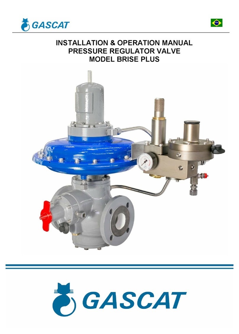
Gascat JR Series User manual

JR Series - Pressure Regulating Valve
Installation, Maintenance and Operation Manual
Gascat –Indústria e Comércio Ltda

Gascat Ind Com Ltda
JR Series - Pressure Regulating Valve
Installation, Maintenance and Operation Manual
MI-03
Prepared by
Approved by
CSQ
Date
Revision
Page
Severino Araújo
Hélcio Teixeira
Rubens Ribeiro
May/18/02
02
2 of 10
CONTENTS
1 –INSTRUCTIONS PRIOR TO COMMISSIONING
Page 3
2 –HEALTH AND SAFETY
Pages 3 / 4
3 –INTRODUCTION
Page 4
4 –OPERATING PRINCIPLE
Page 4
5 –CHARACTERISTICS
Page 5
6 –INSTALLATION
Page 5
7 –OPERATION (START-UP)
Page 6
8 –MAINTENANCE
Page 6
9 –STORAGE
Page 7
10 –GENERAL RECOMMENDATIONS
Page 7
11 –WARRANTY
Page 7
12 –REGULATOR DRAWINGS
Pages 8 / 10

Gascat Ind Com Ltda
JR Series - Pressure Regulating Valve
Installation, Maintenance and Operation Manual
MI-03
Prepared by
Approved by
CSQ
Date
Revision
Page
Severino Araújo
Hélcio Teixeira
Rubens Ribeiro
May/18/02
02
3 of 10
1 –INSTRUCTIONS PRIOR TO COMMISSIONING
It should be clearly understood that the information given under the Commissioning Instructions below do not intend to
revoke or substitute instructions laid out by any relevant entity, and reference should be made to the relevant Standards
and/or existent recommendations on the subject.
It is implied that before Commissioning, the performance of the appropriate "Cleaning and Purification Procedures"
shall be observed and all the instructions contained in "Pressurization" and "Labor Safety and Health Standards" shall be
strictly followed.
The recommendations of valves' suppliers, as for instance, "open slowly" or "open very slowly" should be strictly
observed.
2 –HEALTH AND SAFETY
Regulators, valves, and other pressurized components that contain toxic or flammable gases, or other hazardous
products, are potentially dangerous if not correctly operated and maintained. It is mandatory that all users of these
equipments are properly instructed and warned on their potential danger, and certify yourself that the personnel
responsible for installation, testing, commissioning, operation, and maintenance of the plant are properly skilled to perform
their duties. Instruction manuals are provided for orientation of the operators, but it is supposed that they have a basic
knowledge level. If any doubts or ambiguities remain that could affect the proper procedures ask Gascat Indústria e
Comércio Ltda., which will be pleased to instruct, or to provide the suitable service or instruction. NOT TO TAKE ANY
RISK. Our telephone, fax numbers, and e-mail are the following:
Gascat Indústria e Comércio Ltda.
Rodovia SP 73, 1141 –Indaiatuba / São Paulo.
CEP 13347-990
Brazil
Phone: 55 19 3875-7511
Fax: 55 19 3894-5674
Email: vendas@gascat.com.br
The comments below, while not completely inclusive, provide guidance on possible sources of risk to safety and health.
2.1 –NOISE
Regulators, valves, and other pressure reducers can produce high noise levels, which can be harmful to persons
exposed to them for long time periods. Users should assure themselves that appropriate provisions will be taken, in order
to foresee health safety of employees and/or third parties, according to standards and recommendations in force.
2.2 –INSTALLATION
All equipment, piping, and vessels are designed to support mechanical efforts, as, for instance, torque and bending
momentum, in addition to internal pressure. However, careful shall be exercised during installation not to develop
excessive efforts, which can cause cracks that may result in serious breakage when the regulator is put into operation.
Excessive tensions can also be caused if the equipment is overburden by piping, which should be otherwise appropriately
supported.
All regulators, shutoff valves, relief valves, etc., shall be installed taking into account the correct flow sense.
Impulse lines are important components of any control system and it is essential for them to be correctly installed
according to instructions.
Impulse lines should be appropriately supported to reduce excessive vibration, which can provoke fatigue breakdown.
They should also be positioned so that they cannot serve as support to feet or hands. Impulse lines should have a slight
slope so that liquids and condensates drain towards the main piping.
Auxiliary systems should not be changed, or modified, without knowledge of the operation conditions and permission of
the responsible in charge.

Gascat Ind Com Ltda
JR Series - Pressure Regulating Valve
Installation, Maintenance and Operation Manual
MI-03
Prepared by
Approved by
CSQ
Date
Revision
Page
Severino Araújo
Hélcio Teixeira
Rubens Ribeiro
May/18/02
02
4 of 10
2.3 –OPERATION
Depending on the regulator type, its valve can be positioned fully open. Consequently, when a regulator is put into
operation, the shutoff valves should be opened slowly so that the regulator valve can assume its regulating position. If the
valves are quickly opened, the upstream pressure can pass downstream through the regulator and over-pressurize
downstream the main line.
All regulators, etc., should operate with the regulating spring specified by the manufacturer. This provision is particularly
important when operating relief or shutoff valves, since incorrect springs can hinder a relief valve to open and a shutoff
valve to close.
Provisions should be taken to avoid water input through breathing and ventilation openings.
2.4 –MAINTENANCE
Regulators and valves contain gases under pressure that sometimes are higher than the atmospheric pressure. Before
trying to investigate any problem or to perform service maintenance of the equipment, they should be safely de-
pressurized. Furthermore, as most gases can be flammable, poisonous, corrosive, or somehow, dangerous, it may be
necessary to purge the installation with an inert gas, as nitrogen. Special precautions are necessary for operation with
oxygen or hydrochloric gas and the user should be reassured that appropriate procedures are implemented.
Eventually, it is not enough to isolate the high-pressure device, since high pressures can be retained downstream of
isolation valves. Do not try to remove covers, plugs, etc., before these parts are properly freed-up. Even so, it is advisable
to consider if high-pressure gas can be present at the time of removal of covers and plugs.
Most regulators use spiral springs as the loading device. It is important to reduce the load of these springs relieving their
loaders as much as possible. In some cases, some residual load may last, even though the spring is relaxed to the limits of
its housing.
3 –INTRODUCTION
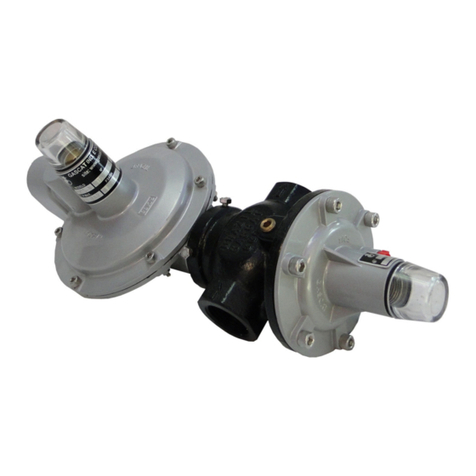
The Series JR regulators are single stage, self-operated regulators for heavy duty work under high, medium, and low
pressure applications, for all types of non-corrosive gases and for corrosive gases, when built in special versions.
These regulators were developed with the purpose of facilitating their maintenance, or parts substitution, as much as
possible. Therefore, because of their top entry characteristic, there is no need to remove them from the line for
maintenance or cleaning. The JR Series regulators are also known for their small weight, constructive simplicity and
soundness.
For valves intended for use with oxygen, all necessary precautions shall be taken for operation with this gas, avoiding
oil or grease presence in tools, and use of lubricants that are not compatible with oxygen. Always use building materials for
the valve that are compatible with the type of used gas.
4 –OPERATING PRINCIPLE
Pressure regulators of the JR Series operate by direct spring action on the output pressure sensor element (diaphragm)
that, with consumption variation and consequent pressure change on the sensor element, will re-position the shutter stem
increasing or reducing the valve aperture, in order to keep the adjusted output pressure constant.
A variation of this system uses external piloting for JR Regulators. Operation is by action of this pilot pressure directly
on the sensor element of the output pressure (diaphragm) that, with consumption variation and consequent pressure
change on the sensor element, in the same way as for regulators operated by direct spring action, will re-position the
shutter shaft increasing or reducing valve aperture, in order to keep constant the adjusted output pressure.
5 –CHARACTERISTICS
FITTINGS: ½” thread (with reduction adapter), ¾”, ¾” x 1”, 1” NPT (according to ANSI B1.20.1) or BSP (according to
BS 21 –DIN 2999); with ½”, ¾” 150# flange, and with 1” 150/300# flange (pursuant ANSI B16.5).
Self-operated regulator by direct spring action.
Open or closed fail-safe condition (the closed condition implies the regulating spring with no pressure at all).
Topy Entry

Gascat Ind Com Ltda
JR Series - Pressure Regulating Valve
Installation, Maintenance and Operation Manual
MI-03
Prepared by
Approved by
CSQ
Date
Revision
Page
Severino Araújo
Hélcio Teixeira
Rubens Ribeiro
May/18/02
02
5 of 10
6 –INSTALLATION
6.1 –Filter
We recommended the installation of a basket type or “Y” filter of 150 mesh (minimum), as close as possible to the
regulator inlet. A careful filter installation is essential to the perfect operation of the equipment, because eventual particles
existing in the piping can lodge themselves between the seat and the shutter, damaging them and provoking direct flow
passage.
6.2 –Cleaning
Check pipeline cleaning before the regulator installation. We recommended a complete purge of the line with nitrogen or
compressed air.
6.3 –Flow Direction
Check the flow direction engraved in the valve body before installation. Junior Series regulators can be installed in any
position.
6.4 –Line Ø
Piping diameter downstream of the regulator should, preferably, be larger than ¾”.
6.5 –Other important devices for a safe installation
A safe installation shall contain, at least (see outline drawing proposed below):
1. Manual blocking valve (ball type, or similar).
2. Filter.
3. Pressure gauge for input pressure reading.
4. Pressure regulator.
5. Pressure gauge for output pressure reading.
6. Manual blocking valve (ball type, or similar).
INSTALLATION OUTLINE

Gascat Ind Com Ltda
JR Series - Pressure Regulating Valve
Installation, Maintenance and Operation Manual
MI-03
Prepared by
Approved by
CSQ
Date
Revision
Page
Severino Araújo
Hélcio Teixeira
Rubens Ribeiro
May/18/02
02
6 of 10
7 –OPERATION (START-UP)
Slowly open the gas inlet valve.
Check if there are no leaks in connections connecting to the regulator.
Adjust the outlet pressure (set-point) turning the regulating screw in the clockwise sense to increase pressure, or in the
counterclockwise sense to reduce it. Perform this operation with a small gas flow.
When the wanted outlet pressure (set-point) is reached, lock the regulating screw with the lock nut.
Check tightness of the shutter/seat assembly. Without gas consumption the output pressure gauge shall present a
quick increase in pressure at closing that shall stabilizes after some seconds.
8 –MAINTENANCE
Defect
Probable Cause
Solution
Outlet pressure
decrease/insufficient flow
Dirt in filter
Check the filter and to proceed its cleaning. For
regulators with external pilot check piloting pressure.
Outlet pressure increasing/direct
passage
Presence of particles between
shutter/seat or worn out shutter
packing.
Remove the shutter by removing the lower plug or,
for JR II regulator, by removing the spring cover and
the seat.
Check if the same is not damaged or dirty,
proceeding its cleaning or replacement as needed.
Check the condition of the sealing border of the
seat, proceeding its replacement if necessary.
Gas passage through the spring
cap vent
Diaphragm rupture.
To loosen the cover of the spring and to replace the
diaphragm.
Vibration.
Worn out shutter and seat
shaft.
Replace the shutter and seat shaft assembly.

Gascat Ind Com Ltda
JR Series - Pressure Regulating Valve
Installation, Maintenance and Operation Manual
MI-03
Prepared by
Approved by
CSQ
Date
Revision
Page
Severino Araújo
Hélcio Teixeira
Rubens Ribeiro
May/18/02
02
7 of 10
9 –STORAGE
The regulators should not suffer mechanical shock, not to risk internal components' damages.
The regulators should be stored at a clean and dry place, protected from bad weather.
10 –GENERAL RECOMMENDATIONS
We test our regulators and valves at the requested operation conditions.
Criteria and maintenance steps are contained in manuals, however, for any doubt on the use, operation, or
maintenance, contact Gascat's technical department that will provide you proper guidance.
Gascat supplies, on request, a complete replacement kit.
11 –WARRANTY
We warrant our products, for a 12 months period from the date of invoicing, if the products are in operation, extending
the warrant up to 18 months, in case they are in stock. Such warranty only covers those cases for which the occurrence of
production defects are evidenced, which remained unnoticed at the time the product delivery.
To present warranty is not valid if it is found that the defect or mishap was caused by accident, normal wear, inadequate
installation, improper maneuvering or use, inadequate storage, assembly disregarding technical standards or if the buyer
undertook repairs or changes in equipment by himself, without the manufacturer's previous authorization.
The information contained in this manual contains Gascat's supply conditions, independently of the verified
performance.
The information herein contained shall not be interpreted or suggest performance warranty in relation to the final
products, or the system usage purpose, nor should they serve as usage recommendation for any product or process
mentioned in the specifications. This system should only be operated by qualified technician trained for this purpose; and
no changes that may affects the system safety can be executed without our previous authorization.
Gascat Ind. and Com. Ltda. withholds the right to make changes without notice, introducing improvements in the
described products drawings or specifications.

Gascat Ind Com Ltda
JR Series - Pressure Regulating Valve
Installation, Maintenance and Operation Manual
MI-03
Prepared by
Approved by
CSQ
Date
Revision
Page
Severino Araújo
Hélcio Teixeira
Rubens Ribeiro
May/18/02
02
8 of 10
Item
Qty.
DESCRIPTION
Drawing Nº
Material
Remarks
1
01
BODY
See Table 1
2
01
TOP COVER
21.005.3
SAE 323
3
01
SEAT
21.007.4
4
01
STEM
21.012.4
5
01
SPRING FOLLOWER
21.010.4
SAE 1020
Yellow Dichromate
6
01
DIAPHRAGM PLATE (For JR A, B & HP)
21.009.4
BRASS
6.1
01
DIAPHRAGM PLATE (For JR A & HP)
21.009.4
BRASS
7
01
PLUG
21.011.4
8
01
SHUTTER
21.008.4
9
01
REGULATING SPRING
SAE 1070
Painted
10
01
SHUTTER SPRING
01.038.4
AISI 302
11
01
REGULATING SCREW
21.014.4
SAE 1020
Yellow Dichromate
12
01
DIAPHRAGM SCREW (For JR A & HP)
21.015.4
12.1
01
DIAPHRAGM SCREW (For JR B)
05.001.4
13
01
NUT 5/8” W.
EB-283
Yellow Dichromate
14
01
NUT 1/2” W.
EB-283
Yellow Dichromate
15
06
HEX. HEAD SCREW ¼” W x ¾”
EB-168
Yellow Dichromate
16
01
PLUG
17
01
SHUTTER GASKET
04.004.4
18
01
DIAPHRAGM
04.001.4
19
02
O’RING
20
01
O’RING for JUNIOR A & HP
21
01
SPRING WASHER
SAE 1070
Yellow Dichromate
22
01
TAG NAMEPLATE
SS
If requested
23
01
PRESSURE GAUGE WITH EXTENSION
24
02
RIVET
SAE 1020
25
01
NAMEPLATE
ALUMINUM
NOTE: () Denotes items of the spare parts kit
Building detail for
Regulating Valve Junior B
TOP VIEW
Flow
Direction

Gascat Ind Com Ltda
JR Series - Pressure Regulating Valve
Installation, Maintenance and Operation Manual
MI-03
Prepared by
Approved by
CSQ
Date
Revision
Page
Severino Araújo
Hélcio Teixeira
Rubens Ribeiro
May/18/02
02
9 of 10
Item
Qty.
DESCRIPTION
MateriaL
Drawing Nº
Remarks
1
01
BODY
FORGED BRASS
21.012.2
SEE NOTE 1.
2
01
SHUTTER STEM
AISI 410
21.012.4
2.1
01
SHUTTER GASKET
VITON
04.004.04
2.2
01
SHUTTER BODY
BRASS
21.008.4
3
01
SIX (6) HOLES SEAT
TM-360
21.024.4
4
01
DIAPHRAGM SCREW
SAE 1020
21.026.4
5
01
TOP PLATE
SAE 1020
21.027.4
6
01
SPRING FOLLOWER
SAE 1020
21.029.4
7
01
REGULATING SCREW
SAE 1020
21.028.4
8
01
COVER
SAE 323
21.013.3
9
01
DIAPHRAGM
BUNA N
04.036.4
10
01
SHUTTER SPRING
AISI 302
01.038.4
11
01
REGULATING SPRING
SAE 1070
SEE TABLE
12
01
O-RING
BUNA N
06.49.18
13
01
¼” NPT VENT
BUNA N
03.49.10
14
08
HEX. HEAD SCREW 5/16” NC x 18 FPP x 11/16”
CLASS 8.8
05.50.66
15
01
HEX. NUT 1/16” NC
CLASS 8.8
05.50.67
16
01
LOWER NUT 9/16” NC
CLASS 8.8
05.50.68
17
01
HOOD
ABS
28.01.54
18
01
HEX PLUG 1/8” NPT
BRASS
03.49.01
19
01
PRESSURE GAUGE
NOTE: () Denotes items of the spare parts kit
Optional

Gascat Ind Com Ltda
JR Series - Pressure Regulating Valve
Installation, Maintenance and Operation Manual
MI-03
Prepared by
Approved by
CSQ
Date
Revision
Page
Severino Araújo
Hélcio Teixeira
Rubens Ribeiro
May/18/02
02
10 of 10
Item
Qty.
DESCRIPTION
Drawing Nº
Material
Remarks
1
01
BODY
21.00.01
NODULAR
2
01
TOP COVER
21.00.25
BRONZE
3
01
SEAT
21.01.01
BRASS
4
01
SHUTTER STEM
21.01.54
AISI 410
5
01
O-RING
06.49.45
BUNA-N
6
01
DIAPHRAGM PLATE
21.01.27
BRASS
7
01
PLUG
21.01.05
SAE 1020
8
01
SHUTTER BODY
21.01.02
BRASS
9
01
DIAPHRAGM
04.49.36
BUNA-N
10
01
SHUTTER SPRING
01.49.40
AISI 302
11
01
SHUTTER GASKET
04.49.47
VITON
12
02
O-RING
06.49.18
BUNA-N
13
01
DIAPHRAGM SCREW
21.01.26
BRASS
14
01
NUT ½” W
05.49.41
EB-283
Yellow Dichromate
15
06
HEX HEAD SCREW ¼” w x ¾”
05.49.55
EB-168
Yellow Dichromate
16
01
SPRING WASHER
05.49.73
SAE 1070
Yellow Dichromate
17
01
PLUG
03.49.01
BRASS
NOTE: () Denotes items of the spare parts kit
PILOT DRIVEN JR REGULATOR
TOP VIEW
Flow Direction
Table of contents
Other Gascat Control Unit manuals
Popular Control Unit manuals by other brands

HPE
HPE G2 R5000 Product End-of-Life Disassembly Instructions

DTS INSIGHT
DTS INSIGHT Micom Pack FH808M07 instruction manual

ICP DAS USA
ICP DAS USA M-7069 quick start guide
Emerson
Emerson Spence K5 instruction manual

Carel
Carel Ultra 3PH user manual
Raven
Raven ISOBUS Product Control Installation & operation manual

Rockwell Automation
Rockwell Automation Allen-Bradley EtherNet/IP user manual

Eaton
Eaton PowerXL DX-NET-DEVICENET manual
SMC Networks
SMC Networks JSY1000 Series manual

SKF
SKF Lincoln 85307 operating instructions

Parker
Parker MT-700 Series Installer's guide
United Technologies
United Technologies Edwards SIGA-CT1 Installation sheet
