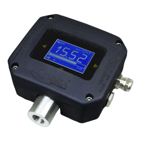
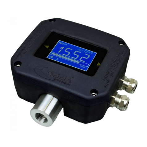
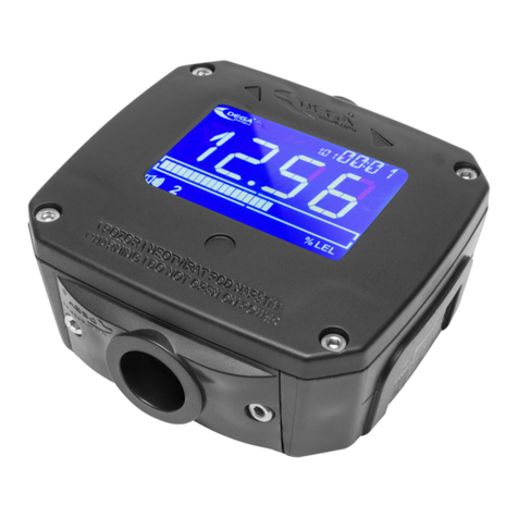
DEGA NB III LCD User manual

INSTRUCTION
MANUAL
Gas Detection Transmitter
DEGA NB III
Reproduction of this manual, or any part thereof, in any form, without the prior permission of DEGA.CZ s.r.o. is
prohibited
DEGA CZ s.r.o. reserves the ri ht to alter the specifications of the hardware and software described in this manual at
any time and without prior notice
DEGA CZ s.r.o. bears no liable for any dama e resultin from use of this device
HRW Limited
www.hrw.hk

2
Content
For your safety .................................................................................................................................................................................. 2
Technical data and information ........................................................................................................................................................ 3
Operational conditions ..................................................................................................................................................................... 4
Terminolo y ...................................................................................................................................................................................... 4
Product description ........................................................................................................................................................................... 5
Assembly and disassembly of the transmitter .................................................................................................................................. 5
1. Assembly of the transmitter ................................................................................................................................................. 5
2. Replacement of the sensor module ...................................................................................................................................... 6
3. Connectin the transmitter via current loop to the controler DEGA UPA II/DEGA UPA III .................................................. 6
4. Connectin the sensor via RS485 to the controller DEGA UKA III/DEGA UPA III/UDA III ..................................................... 6
5. Installation of wirin for RS485 ............................................................................................................................................. 6
6. Settin the RS485 adress of the transmitter......................................................................................................................... 6
7. Terminatin resistor .............................................................................................................................................................. 7
Transmitter functions ....................................................................................................................................................................... 7
1. Turnin on the transmitter ................................................................................................................................................... 7
2. Gas detection ........................................................................................................................................................................ 7
3. Malfunction ........................................................................................................................................................................... 7
4. Monitorin the calibration periods ....................................................................................................................................... 7
Operation, maintenance, inspection and service of the transmitter ............................................................................................... 7
1. Usa e limits ........................................................................................................................................................................... 7
2. Operation .............................................................................................................................................................................. 8
3. Operation/Maintenance ....................................................................................................................................................... 8
Accessories ........................................................................................................................................................................................ 8
1. Additional bushin DEGA BUSHING for NBxIII ...................................................................................................................... 8
Basic types of transmitters ............................................................................................................................................................... 9
1. Transmitters with a catalytic sensor NBx-CL III ..................................................................................................................... 9
2. Transmitters with an electrochemical sensor NBx-EL III ...................................................................................................... 9
3. Transmitters with an infrared sensor NBx-IL III .................................................................................................................. 11
4. Transmitters with a semiconductor sensor NBx-SL III ........................................................................................................ 11
5. Transmitters with a PID sensor NBx-PID III ......................................................................................................................... 12
Add-on modules .............................................................................................................................................................................. 12
Attachments .................................................................................................................................................................................... 12
1. Chart for settin the transmitter adress ............................................................................................................................. 12
2. Si nalization transmitted by the current loop 4-20 mA ..................................................................................................... 12
3. Content of packa e ............................................................................................................................................................. 12
General warranty terms and conditions ......................................................................................................................................... 13
For your safety
Assamble the transm tter w th the sensor fac ng downwards
To maintain IP protection the transmitter must be assambled with the sensor module facin downwards
Beware of stat c electr c ty
Electronic components are sensitive to static electricity. Do not touch them directly - they may et daman ed!
The dev ce s ntended to be nstalled by a tra ned person
The product is desi ned for installation only by a certified technician. The manufacturer is not liable for dama es resultin
from incorrect or improper handlin .
In case of malfunct on, mmed ately unplug from the power supply
If you notice an unusual smell or smoke emittin from the product, unplu it from the power supply, battery backup and all
other attachments. Continued operation could result in injury or property dama e. After disconnectin , have the device
inspected at an authorized dealer or manufacturer.
HRW Limited
www.hrw.hk

3
The transm tters s des gned for non-explos ve env ronment only
For a potentially explosive environemnt use the transmitters DEGA NSx-yL II (ZONE 2) and NSx-yL III (ZONE 3)
Do not d sassemble the product and ensure aga nst t's contact w th water
Contact with internal components of the product may cause an electric shock. In case of any malfuction entrust the servicin
of the product exclusively to a certified service centre. Contact with water can create a short circuit in the product and
consequent daman e to property or personal injury.
Use appropr ate cable types
To ensure compliance with the parameters of the product, only use cable types recommended in this uide.
D spose of used products and trasm tter sensors w th respect to the env ronment
Transmitter sensors contain hazardous substances. Dispose of them in accordance with the current le islation on
environmental protection.
Use the transm tter only w th the appropr ate cert f ed DEGA products
The device is certified as functionally and technically qualified only with ori inal "DEGA" accessories. In case of usin the
device with any other products the manufacturer is not liable for any dama es that may occur.
Undertake regular funct onal checks and cal brat ons of the transm tter
Perform re ular "CALIBRATION" (settin the detection limits, checkin the responsivness of the sensor, checkin the
functionality of the transmitter) and "OPERATIONAL AND FUNCTIONAL CHECKS" of the entire detenction system (sensor
excitation with subsequent control of optical and audible alarms, tri erin fans, shutdown technolo y, etc.). Perform
calibration and operational and functional checks only at certified service centers with a valid certificate of competence or the
manufacturer.
Warnin : The transmitter automatically checks it's calibration period - the period of validity of it's calibration. After 12 months since the
last calibration (Max. calibration period) the transmitter will transmit this fact to the host system. The transmitter must be calibrated
immediately at a certified service center with a valid certificate of competance or the manufacturer. See section "Monitorin the
calibration peridos“.
Techn cal data and nformat on
Supply volta e: 24 V nominal, operational ran e 8-30 V
Cable connections via 4-20 mA: shielded cable 3 x 1 mm (max. 1200 m)
shielded cable 3 x 1,5 mm (max. 2400 m)
Cable connections via RS485: shielded cable 4 x 0,8 mm (max. 400 m) - see section “ instalation of wirin
for RS485“
Diameter ran e of wires: 0,08-2,5 mm2 – wire, double line cable 0,25-1,5 mm2 – double line cable with
internal space
Output: 4 - 20 mA
RS485 - DEGA protocol
Dimensions without bushin s: 110 x 100 x 50 mm (WxHxD)
Wei ht: 0,3 k
Dead band: max 5% of ran e
Consumpt on/ nput at 24V (output RS485)
Warm
-
Up t me
DEGA NBx
-
EL III
25mA/0,6W
DEGA NBx
-
EL III
max. 180s
DEGA NBx
-
CL III
70mA/1,7W
DEGA NBx
-
CL III
max. 30s
DEGA NBx
-
IL III
50mA/1,2W
DEGA NBx
-
IL III
max. 15s
DEGA NBx
-
SL III
DEGA NBx-PL III PID
70 mA/1,7 W
70 mA/1,7 W
DEGA NBx
-
SL III
DEGA NBx-PL III PID
max. 180 s
max. 15 s
Consumpt on/ nput at 24V (output 4
-
20mA)
T me to stab l ze (>5day w thout power)
DEGA NBx
-
EL III
45mA/1,1W
DEGA NBx
-
EL III
Up to several hours
-
based on sensor type
DEGA NBx
-
CL III
90mA/2,2W
DEGA NBx
-
CL III
max. 1h
DEGA NBx
-
IL III
70mA/1,7W
DEGA NBx
-
IL III
max. 30min
DEGA NBx
-
SL III
DEGA NBx-PL III PID
90mA/2,2 W
90 mA/2,2 W
DEGA NBx
-
SL III
DEGA NBx-PL III PID
max. 1 h
max. 30 min
HRW Limited
www.hrw.hk

4
Response t me (T90)
Sensor l fet me n a clean env ronment
DEGA NBx
-
EL III
max. 180s
-
based on sensor type
DEGA NBx
-
EL III
2 years
DEGA NBx
-
CL III
max. 30s
DEGA NBx
-
CL III
2 years
DEGA NBx
-
IL III
max. 30s
DEGA NBx
-
IL III
5 years
DEGA NBx
-
SL III
DEGA NBx-PL III PID
max. 30 s
max.30 s
DEGA NBx
-
SL III
DEGA NBx-PL III PID
2 years
2 years
Operat onal cond t ons
Ambient temperature: -20 °C to +60 °C (electrochemical, semiconductor and catalytic sensors) -20 °C to +40 °C
(infrared sensors)
Relative humidity: 10-95 % RV
Air pressure: 80-120 kPa
Flow of ambient air: max. 2 m/s - flow directly to the sensor in not allowed
Protection level with a cover: IP 54
Location: BE1 - non-explosive environment
Term nology
The mark ng system for sensors DEGA NBx-yL III:
Gas sensor DEGA NBx-yL III
Series of detectors in non-explosive environment
Type of detected as
Sensor type with linear output
Third eneration product with new DEGA desi n
DEGA NBx-EL III w th an electrochem cal sensor
They operate on the principle of chan e of electrical parameters on the electrodes stored in electrolyte, due to
oxidation/reduction reactions of the detected as on it's surface. These sensors have ood selectivity and the ability to detect
very low concentrations of toxic ases.
DEGA NBx-CL III w th a catalyt c sensor (Pel stor)
They operate on the principle of catalytic combustion - as concentration is measured based on the amount of heat released
in a controlled combustion reaction. The reaction is supported by a suitable temperature and the pressence of a catalyst.
These sensors can be used to detect a broad ran e of flammable ases. The sensors are characterized by fast response,a lon
lifetime and hi h stability. A minimum of 10% of Oxy en in the air is required for it's proper function.
DEGA NBx-SL III w th an nfrared sensor (NDIR)
The top quality scannin method. They operate on the principle of infrared spectroscopy. The sensors have excellent selecivity
in or anic matter, do not require any oxy en in the atmoshpere and are resistant to catalyst poisons (sulfur and silicon
compounds) which cause a chan e of sensitivity of catalytic sensors. The sensors are characterized by hi h stability and a lon
lifetime.
DEGA NSx-SL III w th a sem conductor sensor
They operate on the principle of chan es in electrical conductivity of semiconductors by chan in the concentration of the
detected as. Their advata e is a lon lifetime in a clean environment and a wide ran e of different types of ases and vapors.
Their disadvata e is their low selectivity - the sensor lar ly responds to other ases for which it is not calibrated.
DEGA NBx-PL III LCD PID w th a photo on zat on sensor
The sensitive scannin method for detection of a wide ran e of VOC - volatile or anic compounds. The sensor does not
selectively detect all VOCs in the air at concentrations in ppm.
DegaConf g - sensor adjustin software enablin it's full confi uration and calibration.
HRW Limited
www.hrw.hk

5
Product descr pt on
Bushin s
Hexa on screws 3 mm
Status LED
„ALARM“
Status LED „POWER“
Status LED „ERROR“
Sensor module
Mountin holes
PCB electronics
Jumper connector of
the terminatin
resistor RS485 Terminal block RS485 B Terminal block RS485
A
4-20 mA si nal terminal
block
GND power supply
terminal block
DIP switch for the
RS485 adress
+24V DC Power
supply terminal block
Assembly and d sassembly of the transm tter
Before assemblin , read the valid instalation standarts EN 60079-29-2 (Selection, instalation, use and maintenance of
detectors for combustible ases and oxy en) and EN 45544-4 (Guildelines for the selection, installation, use and maintenance
of detectors of toxic substances).
Secure that the sensor is reachable by air. The transmitter must be in a free area with no obstacles in its way (furniture etc.)
Ensure that the input of the sensor cannot be polluted by layers of dust or other contamination.
To ma nta n IP protect on the transm tter must be assambled w th the sensor module fac ng downwards.
1. Assembly of the transm tter
The transmitter consists of four parts - the body of the transmitter, the removable sensor and bushin s.
Transmitter assembly procedure is as follows:
a) Disassemble the transmitter with the four hexa on socket screws 3 mm
b) Use a screwdriver to break out holes for the bushin s
c) Mount the transmitter on a flat surface with four 6 mm fasteners in hei ht above the floor with the as entrance
facin downwards, as specified by the detected substance
d) Direct the cable trou h the bushin s
e) Connect the wirin to the terminal block accordin to " Installation of wirin for RS485".
f) Assemble the transmitter with the four hexa on sockets scews 3 mm
1
2
3
4
5
6
7
8
1
2
3
4
5
6
7
HRW Limited
www.hrw.hk

6
2. Replacement of the sensor module
This activity must not be performed when the sensor is ener ized
.
In case of need to replace the sensor module with a new piece, unscrew and remove the
cover. Unscrew a pair of 3 mm hexa on screws on the sensor module and carefully remove
the sensor module so as not to dama e the pins of the sensor unit. Carefully insert the new
sensor module – be careful not to bend the pins! Screw the two 3 mm hexa ons screws and
put back the cover. Screw the cover.
3. Connecting the transmitter via current loop to the controler DEGA UPA II/DEGA UPA III
Connect one transmitter to each channel of the controler as shown in the picture below
4. Connecting the sensor via RS4 5 to the controller DEGA UKA III/DEGA UPA III/UDA III
5. Installation of wiring for RS4 5
Wirin must be done usin bus topolo y and accordin to the RS485 principles.
Maximum number of connected transmitters per controler channel is 16 (may be less dependin on the confi uration of the
controller), while the total len th of the connectin cable (electrical distance between the controller and the last transmitter)
should not exceed 400 meters.
Selectin the appropriate type of cable depends on the fire report and the protocol for determinin external influences.
6. Setting the RS4 5 adress of the transmitter
Each transmitter must have a unique adress within the entire bus, otherwise there will be
communication collisions and malfunctions.
The transmitter adress can either be set internally usin the De aConfi pro ram or usin the
DIP switch on the PCB.
If the position 6 (labeled ADD) is in the ON position, then the adress accordin to the settin
of pins 1-5 is considered. Otherwise the adress set in De aConfi is considered.
The adress can be set from ran e 1-31 usin binary values. A table with DIP settin s for
individual adresses is listed in the attachment "Chart for settin the transmitter adress"
HRW Limited
www.hrw.hk

7
7. Terminating resistor
Accordin to the RS485 specifications, the last device on the bus must be endin with a terminatin
resistor 120R. Plu a jumper on the JP2 connector of the last device on the bus to include the 120R
terminatin resistor. In the default confi uaration the jumper connector is not plu ed.
Transm tter funct ons
The detector's motherboard is equipped by status LEDs, which help in detectin problems durin the installation.
LED „POW“ shines at correct power
LED „ALARM“ shines when the alarm level is crossed
LED „ERROR“ shines in case of malfunction or an unstandard situation
1. Turning on the transmitter
After turnin on the power the LED "POW" starts shinin and the LED "ERROR" starts flashin , indicatin a formin sequence
of the sensor and automatic testin procedures, which can take up to 18 0s dependin on the sensor used. The output of the
current loop is 1 mA. Durin this sequence, testin of internal electronics and stabilization of the sensor in order to eliminate
false alarms after turnin on, is takin place. After completion of the formation, a 4 mA current be ins to flow on the output of
the current loop and the transmitter starts workin accordin to it's settin s.
2. Gas detection
The transmitter continuously measures the detected as concentration in the atmoshpere and converts it's current value into
a 4-20 mA si nal or transmits it's value to the evaluation unit via DEGA protocol (RS485).
3. Malfunction
If a malfunction of the electronics or the sensor is found durin operation, the transmitter will continue transmittin via
current loop 0,5 mA. On the PCB this condition is indicated by the yellow „ERROR“ LED.
4. Monitoring the calibration periods
The transmitter continuously checks the calibration validity of the connected sensor.
After 12 months since the last calibration (Max. calibration interval) the LED "ERROR" starts flashin . The connected sensor
must be calibrated immediately. The transmitter will transmit the information about the endin calibration via current loop.
The transmission will be the followin : 10 s transmittin a 4-20 mA si nal informin about the actual as concentration
followin a 1 second interval of 2 mA current.
Operat on, ma ntenance, nspect on and serv ce of the transm tter
1. Usage limits
To maintain proper operation of the transmitter it is neccesery to respect the fact, that step chan es of humidity,
condensation or rapid chan es of pressure can cause incorrect indication of the measured value. Each sensin technolo y is
suited for different methods of application, which is described below. All sensors are characterized by a smaller or lar er cross-
sensitivity to other ases than those which are set. Therefore before processin project documentation we recommend to
have the air in the deployment area of the detection system analyzed.
a) catalyt c sensors: Trace amount of vapors of silicon compounds and sulfur compounds cause a permanent loss of sensitivity,
which requires recalibration or replacement of the sensor. Lon term crossin of the measurin ran e causes a decrease in
sensitivity. In case of an atmoshpere havin an oxy en content of less than 17%, there will be an underestimaton of the
measured value. In case of an atmoshpere havin an oxy en content of more than 25%, there will be an overestimation of the
measured value.
HRW Limited
www.hrw.hk

8
b) electrochem cal sensors: Constant exposure to toxic ases or short-term exposure to ases, which reatly exceed the
maximum ran e of the sensor, can dama e the electrochemical sensor, which requires recalibration or replacement. Hi h
temperature alon with low relative humidity have a ne ative effect on the sensor's lifetime. In case of an atmoshpere havin
an oxy en content of less than 1 % for lon er than 1 hour, there will be an underestimation of the measured value.
c) nfrared sensors: Vapor acids and alkalis can etch the optical system and distort the measurements. A check or a calibration
may be neccesery.
d) sem conductor sensors: Short-term exposure to ases or vapors of or anic solvents, which reatly exceed the maximum
ran e of the sensor, may dama e the sensor and a recalibration or replacement may be required. In case of an atmoshpere
havin na oxy en content of less than 18 %, there will be an underestimation of the measured value.
e) photo on zat on sensors: the UV lamp or sensor must be replaced re ularly, as its clo in of can cause loss of si nal.
2. Operation
To maintain proper operation of the transmitter it is neccesery to respect the fact, that the presence of certain concentrations
of ases or vapors, other than those for which the sensor is set, can cause an alarm, even if the concentration of the as does
not exceed the set level. Given the ran e of disturbin ases or vapors (diluents, exhaust ases, vapors of or anic substances,
disinfectants, etc.) a enerally allowable concentration of interferin ases can not be determined. Data on cross-sensitivity to
certail ases are included at the apporpriate sensors. Therefore before processin project documentation we recommend to
have the air in the deployment area of the detection system analyzed.
3. Operation/Maintenance
In case of contamination the surface can be cleaned with a sli htly moistened cloth.
The seonsors have a different lifetime dependin on the sensin technolo y used, and environmental conditions.
Characteristics of the sensors vary over time. Therefore it is required to perform re ular checks and calibrations, which can be
done in two ways:
a) 1 x every s x months carry out a „cal brat on“ and funct onal control - adjust the sesitivity of the sensor usin
calibration as and check the functionality of the system. The exact interval depends on the purity of the environment,
required accuracy and the occurrance of disturbin ases in the atmoshpere.
b) 1 x every twelve months carry out a „cal brat on“ - adjust the sesitivity of the sensor usin calibration as and check the
functionality of the system. The exact interval depends on the purity of the environment, required accuracy and the
occurrance of disturbin ases in the atmoshpere. Also carry out a „funct onal control" 1 x every three months -
checkin the function of the entire detection system usin a test as, which does not exceed the ran e of the sensor.
We recommend usin as intended for laboratory use.
For the „funct onal control“ do not use means for test ng f re alarm detectors!
Perform calibration only at certified service centers with a valid certificate of competence or the manufacturer.
For the Czech Republ c only DEGA CZ s.r.o.
Accessor es
1. Additional bushing DEGA BUSHING for NBxIII
PG9
HRW Limited
www.hrw.hk

9
Bas c types of transm tters
1. Transmitters with a catalytic sensor NBx-CL III
Product code Transmitter type Detected as Measurement
ran e
Measurement of
current loop
(4-20 mA)
Resolution Calibration as
20100075 DEGA NBM-CL 100 III
Methane (CH4)
Natural as
CNG
0–100 % LEL 0-20 % LEL 0,1 % LEL Methane 0,88 %
20100076 DEGA NBP-CL 100 III
Butane (C4H10)
Propan-Butane
LPG
0–100 % LEL 0-20 % LEL 0,1 % LEL Butane 0,32 %
20100074 DEGA NBH-CL 100 III Hydro en (H2) 0–100 % LEL 0-20 % LEL 0,1 % LEL Hydro en 0,8 %
20100077
DEGA NBHC-CL 100 III
Other
flammable and
combustible
ases and
vapors
accordin to
the selectivity
of the sensor
0–100 % LEL 0-20 % LEL 0,1 % LEL Accordin to the selectivity of the
sensor
2. Transmitters with an electrochemical sensor NBx-EL III
Product code Transmitter type Detected as Measurement
ran e
Measurement of
current loop
(4-20 mA)
Resolution Calibration as
20100028 DEGA NBCO-EL 1000 III Carbon
Monoxide (CO) 0–1000 ppm 0-130 ppm 1 ppm Carbon Monoxide
450 ppm
20100025 DEGA NBCO-EL 200 III Carbon
Monoxide (CO) 0–200 ppm 0-200 ppm 0,1 ppm Carbon Monoxide
130 ppm
20100027 DEGA NBCO-EL A500 III Carbon
Monoxide (CO) 0–500 ppm 0-200 ppm 0,1 ppm Carbon Monoxide
130 ppm
20100029 DEGA NBCO-EL 2000 III Carbon
Monoxide (CO) 0- A500 ppm 0-500 ppm 1 ppm Carbon Monoxide
130 ppm
20100026 DEGA NBA-EL 100 III Carbon
Monoxide (CO) 0–2000 ppm 0-2000 ppm
1 ppm Ammonia
100 ppm
20100045
DEGA NBA-EL 1000 III Ammonia
(NH3)
0-100 ppm
0-50 ppm
0,1 ppm
Ammonia
100 ppm
20100047
DEGA NBA-EL 10000 III Ammonia
(NH3)
0-1000 ppm
0-300 ppm
1 ppm
Ammonia
100 ppm
20100050
DEGA NBA-EL 500 III Ammonia
(NH3)
0-10000 ppm
0-10000 ppm
1 ppm
Ammonia
100 ppm
20100046 DEGA NBA-EL 5000 III Ammonia
(NH3)
0-500 ppm
0-500 ppm
1 ppm
Ammonia
1000 ppm
20100049 DEGA NBA-EL 2000 III Ammonia
(NH3)
0-5000 ppm
0-5000 ppm
1 ppm
Ammonia
1000 ppm
20100048 DEGA NBCL2-EL 20 III Ammonia
(NH3)
0-2000 ppm
0-2000 ppm
1 ppm
Chlorine
5 ppm
20100022 DEGA NBCL-EL 200 III Chlorine
(Cl2) 0-20 ppm 0-5 ppm 0,01 ppm Chlorine
50 ppm
20100023 DEGA NBO2-EL 1 III Chlorine
(Cl2)) 0-200 ppm 0-200 ppm 0,1 ppm Air
20100057 DEGA NBO2-EL 30 III Oxy en (O2) 0-1 % 0-1 % 0,01 % Air
20100058 DEGA NBO2-EL T30 III Oxy en (O2) 0-100 % 0-30 % 0,1 % Air
20100059 DEGA NBO3-EL 5 III Oxy en (O2) 0-100 % 0-30 % 0,1 % Chlorine
5 ppm
20100061 DEGA NBO3-EL 100 III Ozone (O3) 0-5 ppm 0-0,2ppm 0,01ppm Chlorine
5 ppm
20100060 DEGA NBHCL-EL 20 III Ozone (O3) 0-100 ppm 0-100 ppm 0,1ppm Hydro en chloride
10 ppm
20100041 DEGA NBHCL-EL 200 III Hydro en
chloride (HCl) 0-20 ppm 0-10 ppm 0,01 ppm Hydro en chloride
25 ppm
HRW Limited
www.hrw.hk

10
20100042 DEGA NBH2S-EL 50 III Hydro en
chloride (HCl) 0-200 ppm 0-200 ppm 0,1 ppm Hydro en sulfide 25 ppm
20100038 DEGA NBH2S-EL 500 III Hydro en sulfide
(H2S) 0-50 ppm 0-15 ppm 0,1 ppm Hydro en sulfide 500 ppm
20100036 DEGA NBH2S-EL 100 III Hydro en sulfide
(H2S) 0-500 ppm 0-500 ppm 1 ppm Hydro en sulfide 25 ppm
20100035 DEGA NBH2S-EL 2000 III Hydro en sulfide
(H2S) 0-100 ppm 0-100 ppm 0,1 ppm Hydro en sulfide 2000 ppm
20100037 DEGA NBNO2-EL 20 III Hydro en sulfide
(H2S) 0-2000 ppm 0-2000 ppm 1 ppm Nitro en dioxide 20 ppm
20100054 DEGA NBNO2-EL 100 III Nitro en dioxide
(NO2) 0-20 ppm 0-15 ppm 0,01 ppm Nitro en dioxide 20 ppm
20100055 DEGA NBNO2-EL 500 III Nitro en dioxide
(NO2) 0-100 ppm 0-100 ppm 0,1 ppm Nitro en dioxide 100 ppm
20100056 DEGA NBNO-EL 250 III Nitro en dioxide
(NO2) 0-500 ppm 0-500 ppm 1 ppm
Nitric oxide 150 ppm
20100052 DEGA NBNO-EL 25 III Nitric oxide (NO) 0-250 ppm 0-15 ppm 0,1 ppm
Nitric oxide 15 ppm
20100051 DEGA NBNO-EL 1000 III Nitric oxide (NO) 0-25 ppm 0-25 ppm 0,1 ppm
Nitric oxide 150 ppm
20100053 DEGA NBSO2-EL 20 III Nitric oxide (NO) 0-1000 ppm 0-100 ppm 1 ppm Sulfur dioxide 10 ppm
20100070 DEGA NBSO2-EL 200 III Sulfur dioxide
(SO2) 0-20 ppm 0-3,5 ppm 0,01 ppm Sulfur dioxide 50 ppm
20100071 DEGA NBSO2-EL 2000 III Sulfur dioxide
(SO2) 0-200 ppm 0-200 ppm 0,1 ppm Sulfur dioxide 1000 ppm
20100072 DEGA NBSO2-EL 100 III Sulfur dioxide
(SO2) 0-2000 ppm 0-2000 ppm 1 ppm Sulfur dioxide 50 ppm
20100067 DEGA NBSO2-EL 1000 III Sulfur dioxide
(SO2) 0-100 ppm 0-100 ppm 0,1 ppm Sulfur dioxide 1000 ppm
20100068 DEGA NBSO2-EL 10000 III Sulfur dioxide
(SO2) 0-1000 ppm 0-1000 ppm 1 ppm Sulfur dioxide 1000 ppm
20100069 DEGA NBCH2O-EL 10 III Sulfur dioxide
(SO2) 0-10000 ppm 0-10000 ppm 1 ppm Carbon Monoxide 130 ppm
20100011 DEGA NBCH2O-EL 1000 III Formaldehyde
(CH2O) 0–10 ppm 0-0,7 ppm 0,01 ppm Carbon Monoxide 450 ppm
20100013 DEGA NBCH2O-EL 50 III Formaldehyde
(CH2O) 0–1000 ppm 0-1000 ppm 1 ppm Carbon Monoxide 130 ppm
20100012 DEGA NBC2H4-EL 10 III Formaldehyde
(CH2O) 0–50 ppm 0-50 ppm 0,1 ppm Ethylene 2 ppm
20100014 DEGA NBC2H4-EL 1500 III Ethylene (C2H4) 0–10 ppm 0-10 ppm 0,01 ppm Ethylene 200 ppm
20100015 DEGA NBC2H4-EL 200 III Ethylene (C2H4) 0–1500 ppm 0-1500 ppm 1 ppm Ethylene 200 ppm
20100016 DEGA NBC2H4O-EL 10 III Ethylene (C2H4) 0–200 ppm 0-200 ppm 0,1 ppm Ethylene oxide 2 ppm
20100017 DEGA NBC2H4O-EL 100 III Ethylene oxide
(C2H4O) 0–10 ppm 0-1,5 ppm 0,01 ppm Ethylene oxide 100 ppm
20100018 DEGA NBC2H4O-EL 1000 III Ethylene oxide
(C2H4O) 0–100 ppm 0-100 ppm 0,1 ppm Ethylene oxide 100 ppm
20100019 DEGA NBC2H4O-EL 500 III Ethylene oxide
(C2H4O) 0–1000 ppm 0-1000 ppm 1 ppm Ethylene oxide 100 ppm
20100020 DEGA NBH-EL III 1000 Ethylene oxide
(C2H4O) 0–500 ppm 0-500 ppm 1 ppm Hydro en
1000 ppm
20100030 DEGA NBH-EL 4000 III Hydro en
(H2) 0–1000 ppm 0-400 ppm 1ppm Hydro en
1000 ppm
20100031 DEGA NBH-EL 40000 III Hydro en
(H2) 0–40000 ppm 0-4000 ppm 1ppm Hydro en 0.8% vol
20100032 DEGA NBHCN-EL 50 III Hydro en
(H2) 0–400000 ppm 0–100 % LEL 0,1 % Hydro en sulfide 1 ppm
20100043 DEGA NBPH3-EL 5 III Hydro en
cyanide (HCN) 0–50 ppm 0-50 ppm 1 ppm Hydro en sulfide 25 ppm
20100065 DEGA NBPH3-EL 20 III Phosphine
(PH3)
0–5 ppm
0-0,2 ppm 0,01 ppm Hydro en sulfide 25 ppm
20100062 DEGA NBPH3-EL 200 III Phosphine
(PH3)
0–20 ppm
0-20 ppm 0,01 ppm Hydro en sulfide 25 ppm
20100063 DEGA NBPH3-EL 2000 III Phosphine
(PH3)
0–200 ppm
0-200 ppm 0,1 ppm Hydro en sulfide 250 ppm
20100064 DEGA NBSIH4-EL 50 III Phosphine
(PH3)
0–2000 ppm
0-2000 ppm 1 ppm Hydro en sulfide 25 ppm
20100066 DEGA NBCLO2-EL 5 III Silane (SiH4) 0–50 ppm 0-5 ppm 0,1 ppm Chlorine
5 ppm
HRW Limited
www.hrw.hk

11
20100024 DEGA NBH2O2-EL 100 III Chlorine dioxide
(ClO2) 0-1 ppm 0-0,4 ppm 0,01 ppm Sulfur dioxide 25 ppm
20100033 DEGA NBH2O2-EL 500 III
Hydro en
peroxide
(H
2
O
2
)
0-100 ppm 0-100 ppm 0,1 ppm Sulfur dioxide 250 ppm
20100034 DEGA NBHBr-EL 20 III
Hydro en
peroxide
(H
2
O
2
)
0-500 ppm 0-500 ppm 1 ppm Hydro en sulfide 25 ppm
20100039 DEGA NBHBr-EL 200 III
Hydro en
bromide
(HBr)
0-20 ppm 0-20 ppm 0,01 ppm Hydro en sulfide 250 ppm
20100040 DEGA NBHF-EL 10 III
Hydro en
bromide
(HBr)
0-200 ppm 0-200 ppm 0,1 ppm Nitro en dioxide 20ppm
20100044 DEGA NBVOC-EL 20 III Hydro en
fluoride (HF) 0-10 ppm 0-10 ppm 0,01 ppm VOC 20ppm
20100073 DEGA NBBR2-EL 20 III VOC 0-20 ppm 0-20 ppm 0,01 ppm Chlorine
5 ppm
20100009 DEGA NBBR2-EL 200 III Bromine (Br) 0-20 ppm 0-20 ppm 0,01 ppm Chlorine
50 ppm
20100010 DEGA NBALC-EL 200 III Bromine (Br) 0-200 ppm 0-200 ppm 0,1 ppm Ethanol 200 ppm
20100008 DEGA NBRCOOH-EL 100 III Alkohol 0-200 ppm 0-200 ppm 0,1 ppm Ammonia
300 ppm
20100021 DEGA NBCS2-EL 100 III Or anic acids 0-100 ppm 0-100 ppm 0,1 ppm Carbon disulfide 50ppm
3. Transmitters with an infrared sensor NBx-IL III
Product code Transmitter type Detected as Measurement
ran e
Measurement of
current loop
(4-20 mA)
Resolution Calibration as
20100081 DEGA NBCO2-IL 5 III Carbon dioxide
(CO2) 0-5 % vol. 0-2,5 % vol. 0,1 % Carbon dioxide
2,5 % vol.
20100082 DEGA NBCO2-IL HC III Carbon dioxide
(CO2) 0-100 % vol. 0-2,5 % vol. 0,1 % Carbon dioxide
2,5 % vol.
20100083 DEGA NBCO2-IL 500 III Carbon dioxide
(CO2) 0-500 ppm 0-2,5 % vol. 0,1 % Carbon dioxide
2,5 % vol.
20100085 DEGA NBM-IL 100 III
Methane (CH4)
/ Natural as
/Coal as / CNG
0–100 % LEL 0-20 % LEL 0,1 % Methane 0,88 % LEL
20100086 DEGA NBP-IL 100 III Butane / LPG
/ Propane-Butane 0–100 % LEL 0-20 % LEL 0,1 % Butane 0,32 % LEL
20100090 DEGA NBC2H6-IL 100 III Ethane
(C2 H6) 0–100 % LEL 0-20 % LEL 0,1 % Ethane 20 % LEL
20100088 DEGA NBC2H5OH-IL 100 III Ethanol
(C2 H5OH) 0–100 % LEL 0-20 % LEL 0,1 % Ethanol 20 % LEL
20100089 DEGA NBC2H4-IL 100 III Ethylen (C2H4) 0–100 % LEL 0-20 % LEL 0,1 % Ethene 20 % LEL
20100087 DEGA NBC2H4O-IL 100 III Etyhelen oxide
(C2H4O) 0–100 % LEL 0-20 % LEL 0,1 % Etyhelen oxide 20 % LEL
20100093 DEGA NBC6H14-IL 100 III Hexane
(Petrol) 0–100 % LEL 0-20 % LEL 0,1 % Hexane 20 % LEL
20100094 DEGA NBN2O-IL 1 III Nitrous oxide
(N2O) 0-1 % LEL 0-0,5 % LEL 0,01 % Nitrous oxide 0,5 % LEL
20100092 DEGA NBC5H12-IL 100 III Pentane
(C5H12) 0–100 % LEL 0-20 % LEL 0,1 % Pentane 20 % LEL
20100091 DEGA NBC3H6-IL 100 III Propylene
(C3H6) 0–100 % LEL 0-20 % LEL 0,1 % Propylene 20 % LEL
20100084 DEGA NBHC-IL 100 III
Other flammable
and combustible
ases and vapors
accordin to the
selectivity of the
sensor
0–100 % LEL 0-20 % LEL 0,1 % Hexane 0,18 % LEL
4. Transmitters with a semiconductor sensor NBx-SL III
Product code Transmitter type Detected as Measurement
ran e
Measurement of
current loop
(4-20 mA)
Resolution Calibration as
20100080 DEGA NBY-SL 100 III Acetylene (C2H2) 0–100 % LEL 0-20 % LEL 0,1 % 20 % LEL
20100079 DEGA NBR-SL 2000 III Refrigerant:
R401A, R404A,
R407C, R32,
R410A, R12, R22
0–2000 ppm 0-2000 ppm 1 ppm According to the type of refrigerant
20100078 DEGA NBHFO-SL 2000 III Refrigerant:
R1234yf 0–2000 ppm
0-2000 ppm 1 ppm According to the type of refrigerant
HRW Limited
www.hrw.hk

12
5. Transmitters with a PID sensor NBx-PID III
Product code Transmitter type Detected as Measurement
ran e
Measurement of
current loop
(4-20 mA)
Resolution Calibration as
20100095 DEGA NBVOC-PID III VOC 0–4000 ppm 0-500 ppm 0,1ppm Izobutylene 300ppm
LEL - Lowest explosion level
ALARM "PEL": Permitted exposure limit - maximal permitted value of the avara e concentration over time.
Alarm settin s can be chosen freely accordin to customer requirements in measurement ran e.
Add-on modules
Product code
Name
Product description
20200009
DEGA NB III RS485
Internal output RS485
Attachments
1. Chart for setting the transmitter adress
adress
1
2
3
4
5
1
ON
OFF
OFF
OFF
OFF
2
OFF
ON
OFF
OFF
OFF
3
ON
ON
OFF
OFF
OFF
4
OFF
OFF
ON
OFF
OFF
5
ON
OFF
ON
OFF
OFF
6
OFF
ON
ON
OFF
OFF
7
ON
ON
ON
OFF
OFF
8
OFF
OFF
OFF
ON
OFF
9
ON
OFF
OFF
ON
OFF
10
OFF
ON
OFF
ON
OFF
11
ON
ON
OFF
ON
OFF
12
OFF
OFF
ON
ON
OFF
13
ON
OFF
ON
ON
OFF
14
OFF
ON
ON
ON
OFF
15
ON
ON
ON
ON
OFF
16
OFF
OFF
OFF
OFF
ON
adress
1
2
3
4
5
17
ON
OFF
OFF
OFF
ON
18
OFF
ON
OFF
OFF
ON
19
ON
ON
OFF
OFF
ON
20
OFF
OFF
ON
OFF
ON
21
ON
OFF
ON
OFF
ON
22
OFF
ON
ON
OFF
ON
23
ON
ON
ON
OFF
ON
24
OFF
OFF
OFF
ON
ON
25
ON
OFF
OFF
ON
ON
26
OFF
ON
OFF
ON
ON
27
ON
ON
OFF
ON
ON
28
OFF
OFF
ON
ON
ON
29
ON
OFF
ON
ON
ON
30
OFF
ON
ON
ON
ON
31
ON
ON
ON
ON
ON
32
OFF
OFF
OFF
OFF
ON
2. Signalization transmitted by the current loop 4-20 mA
Measurement: The measure concentration is directly proportional to 4-20 mA current output
Exceed ng the range of measured concentrat ons: Current output ran es from 20-22 mA
End of val d cal brat on: Current output transmits the actual measured concentration for 9 s in a 4-20 mA ran e and for
1 s 2 mA current
Malfunct on: Current output will be set to 0,5 mA
Serv ce ntervent on (form ng sequence of the sensor): Current output will be set to 1 mA
3. Content of package
1 x sensor
1 x bushin
HRW Limited
www.hrw.hk

13
General warranty terms and cond t ons
When follow ng the nstruct ons for nstallat on, operat on and ma ntenance, the manufacturer guarantee 24 months from
the date of rece pt for the product. Should the product purchased be put into operation by an entity other than the seller, the
warranty period commences from the date that the product is put into operation, provided that the buyer ordered its
commissionin within three weeks of its receipt. The customer expressly acknowled es that durin the warranty period that
extends beyond the len th of the warranty period that is specified in the Commercial Code (the statutory warranty) s/he can
neither require replacement of the product nor may s/he withdraw from the contract.
1. When claimin a product defect it is necessary to submit a proof of purchase that contains the followin information:
name and surname, name and business name, address and the warranty card, if the buyer received one from the seller.
The validity of the warranty shall not be affected by non-compliance with the obli ations related to the issuance of the
warranty card.
2. Claims concernin the product (for a warranty repair only complete devices are accepted) may be filed durin the
warranty period only with the seller from which it was purchased; subsequently the seller is required to forward the
product to an authorised service centre or to the manufacturer.
3. A condition for the reco nition of the ri hts under the warranty is the installation of the product havin been undertaken
by an authorised person in possession of a valid certificate from the manufacturer.
5. Claims re ardin a product defect that can be dealt with reasonably quickly and without additional consequences will be
resolved by remedyin the defect (repair) or by replacement of the product part , because in such a case it is a
contradiction of the standard norms that the entire product shall be replaced (§ 616, para raph 4 of the Commercial
Code).
6. The buyer who exercises the ri ht of warranty repair is not entitled to the return of the parts that have been replaced.
7. The warranty period can be extended for up to 48 months and its validity can be extended beyond the standard len th on
the basis of the conclusion of an individual warranty contract. Further information may be obtained throu h a specific
business meetin
This warranty is not applicable to:
•a product that has not been put nto operat on by the manufacturer or by a cert f ed employee in possession of a valid
certificate issued by the manufacturer
•A product that did not have re ulary performed calibrations and functional checks by the manufacturer or by a certified
employee is possession of a valid certificate issued by the manufacturer.
•dama e caused by fire, water, static electricity, power sur es in the electric supply or in the public network, accident,
improper use of the product, wear and tear
•contamination of the product and its subsequent cleanin
•dama e caused by mproper nstallat on, any adjustment, mod f cat on or improper manner of use inconsistent with the
instruction manual, the technical standards or the applicable safety re ulations in the Czech Republic
•dama e to the product durin transportation caused by improper handlin or handlin of the product in a manner
contrary to the advice provided in the instruction manual
•DEGA products that have been used n assoc at on w th other than or g nal DEGA products, includin consumables and
accessories
•transm tter cal brat ons, settin the detection limits
•detor at on or destruct on of the sensors, nclud ng the r replacement
•bearin additional parts or consumables (e. . a foil label, seal, etc.), that are detrimental to normal wear and tear durin
operation, to ether with wear and tear of the product and its parts caused by their normal use.
For the complete version of the eneral business conditions and of the claims procedure o to www.de a.cz
Manufacturer: DEGA CZ s.r.o., Malešická 2850/22c, 130 00 Praha 3, Czech republic
Tax ID: CZ 279 029 43, IČO: 279 02 943, Telephone +420 774 447 660, E-mail: info@de a.cz, Web: www.de a.cz
© 2021 DEGA CZ s.r.o. User Manual ver.: 27/08/2021 14:17:00
HRW Limited
www.hrw.hk
Other manuals for NB III LCD
1
Table of contents
Other DEGA Gas Detector manuals