Gates GC16XD Installation manual

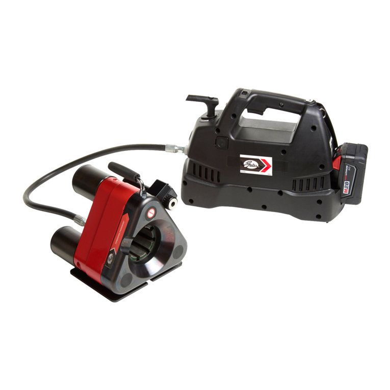
GC16XD MINI CRIMPER & PUMP
SAFETY AND OPERATING MANUAL
Part Number 70115
Product Number 7480-7006

CRIMPER DETAILS GC16XD MINI CRIMPER & PUMP SAFETY AND OPERATION MANUAL
Serial No. ____________________________
Date of Purchase _____________________
YOUR CRIMPER DETAILS
CRIMPER SPECIFICATIONS
DYNAMIC
Nom. Size (Hydraulic Hose Size) 1 Inches
Die Set Type 16 Series
Crimping Range (Inch with Std. Die Set) 1/4 to 1 Inch
Radial Swaging Force 900kN / 90 Tonne
Approx. Cycle Speed (Full Stroke) 18 Sec (Power Unit Dependant)
PHYSICAL
Dimensions ( W x D X H) 0.21 x 0.22 x 0.22m / 8.7 x 8.75 x 8.75 In
Weight (Without Dies & Oil lbs) 22 kg / 48.5
Shipping Dimensions 0.30 x 0.40 x 0.39m /12.2 x 16.14 x
15.74 In
Shipping Weight 23.5Kg / 54lb
HYDRAULIC
Rated Pressure 690 Bar / 10,000 PSI
Reservoir Capacity (Min) 0.8 Litres / 0.2 Gallons
Recommended Filtration 10um
Oil Specification See Power Unit Requirements
MAINTENANCE Grease Specification Tungsten Disulphide

1
TABLE OF CONTENTS GC16XD MINI CRIMPER & PUMP SAFETY & OPERATION MANUAL
CRIMPER SAFETY 2
BOX CONTENTS 7
GETTING TO KNOW YOUR CRIMPER 8
Dial Indicator 8
Power Unit 8
E-Crimp Settings 9
Quick-Connect Fitting 10
Grease Application 10
Carrying & Movement 10
Die Loading/Insertion 11
HOSE PREPARATION 12
MEASURING CRIMP DIAMETER 13
CALIBRATION 14
PERIODIC MAINTENANCE 16
REPLACEMENT PARTS 17
WARRANTY 19

2
CRIMPER SAFETY GC16XD MINI CRIMPER & PUMP SAFETY & OPERATION MANUAL
WARNING
An incorrect hose assembly can rupture or blow apart in use, resulting in serious injury, death,
or property damage.
REMEMBER: Others depend on you to make correct assemblies.
Hose Assembly Fabrication.
■Component inspection: Before creating an assembly be sure to inspect all components to ensure
they are the correct product, cut correctly, and do not have any visually identifiable defects.
■Couplings (compatibillity): Hose fitting components from one manufacturer are not usually
compatable with fitting components supplied by another manufactuerer. Never mix and match hose
couplings from different manufacturers unless approved by both parties.
■Hose assembly equipment (crimpers): Hoses and fittings from one manufacturer should not generally
be assembled with the equipment of another manufacturer.
NOTE: Gates recommends only those hose and coupling combinations specified in the Gates Hydraullic
Product catalogs. Gates disclaims any liabillity for any hose assemblies which have not been produced in
conformance with Gates assembly recommendations.
WARNING
Carefully read and understand the following warnings before operating this crimper.
FOR SAFETY’S SAKE USE THIS MACHINE ONLY IF YOU:
1. Recieve hands-on TRAINING whith this Gates crimper and assemblies.
2. Follow current GATES OPERATING MANUAL and CRIMP DATA for the GC16XD crimper.
3. Use only NEW (UNUSED GATES) hose and fittings.
4. Wear SAFETY GLASSES.
5. Keep hands clear of moving parts.
!

3
CRIMPER SAFETY GC16XD MINI CRIMPER & PUMP SAFETY & OPERATION MANUAL
WARNING
This Safety & Operation Manual has been provided for yours and other’s safety. Every operator MUST have
completed training and have an understanding of the crimper and the requirements of hose assemblies
before using this machine.
It is the responsibility of the owner of this crimper to ensure that ONLY persons who have an understanding of
the local regulations for work safety and accident prevention in addition to undertaken training on using this
crimper be allowed to operate this machine.
It is the responsibility of the operator of this crimper to observe the rules and guidelines set out in this manual
and those provided by the owner of this machine.
This Safety & Operational Manual MUST be located near the crimper at all times and be used as a
reference when required. Regulations for Work Safety and Prevention of accidents MUST also be available to
the operator of this crimper.
WARNING
Every crimper has been engineered to the hightest possible standard and thoroughly tested prior to release.
Regardless of this, dangerous situations can arise if the safety rules and regulations are not respected or be
part of the work process when using this crimper.
!

4
GC16XD MINI CRIMPER & PUMP SAFETY & OPERATION MANUAL
CRIMPER SAFETY
WARNING
This Gates crimper has been engineered and qualified for Gates product ONLY. Crimping any NON-GATES fluid
power product, including miscellaneous items (cable/pipe) through the machine will not only VOID Warranty
but also breech the intended use and purpose condition and basic regulations of work safety and accident
prevention.
Intended use and purpose outlined in this manual also includes regular maintenance. Failure to use the
specified grease will also VOID Warranty.
Warranty and Liability
The terms and conditions of sale and delivery shall apply. A copy of these terms and condition can be
provided on request, but generally include conditions for inteded use and purpose, improper observation
concerning transport, storage & maintenance, unauthorized use, constructional changes or repairs and failure
to detect wear.
Only authorized/qualified electricians are to work on the electrical system of Gates crimpers.
It is the responsibility of the operator to ensure that no oil from this crimper is allowed to seep into the
ground, in accordance to pollution rules of the Water Resource Management Laws.
1. Avoid contact with oil for prolonged periods.
2. Keep work place clear of objects and trip hazards.
3. Wear safety equipment at all times when operating the machine.
4. Keep body parts away from the machine when in use, do not put hands in crimper when operational.

5
GC16XD MINI CRIMPER & PUMP SAFETY & OPERATION MANUAL
CRIMPER SAFETY
WARNING
Intended Design Use
This machine must not be used for high volume daily production. It is designed for periodic use only. Using
this machine other than for its intended purpose will void manufacturers warranty and could result in failure
which may cause injury or loss of life.
Personal Safety
Regardless of local accident prevention regulations, the following should be observed to maintain the health
and safety of operators.
1. Always wear protective clothing and apparatus as oulined in the local accident prevention regulations.
2. Ensure that safety and danger notifications have been observed.
3. Make sure the work area is clear of obstructions and is a suitable work environment.
4. Never start the machine unless intending to make a hose assembly and the head is free of objects
and persons.
5. ONLY operate this machine if the ambient temerature is between 50ºF ~ 95ºF (10ºC and 35ºC)
6. Never reach into the crimper while head is moving.
7. Never change die sets unless the head is completely open.
8. The power MUST be disconnected for crimper maintenance.
9. Observe machine balance point when moving the crimper.
10. Never try and lift this crimper when there is a possibility of oil on the handle.

6
CRIMPER SAFETY GC16XD MINI CRIMPER & PUMP SAFETY & OPERATION MANUAL
WARNING
LIFTING AND MOVEMENT
The handle is designed for manual lifting only. Do not use as a lifting point for slings, doing so may result in
crimper falling and injuring personnel.

7
GC16XD MINI CRIMPER & PUMP SAFETY & OPERATION MANUAL
BOX CONTENTS
Included in the carton with GC16XD
will be TDS start up kit, calibration
tools and a set of calipers.
GC16XD (PART# 7480-7006)
• Tungston Disulphide Start-Up Kit
• Calipers
• Calibration/Maintenance Tools
Optional Extra:
Quick Change Tool (7482-7304)
CALIPERS QUICK CHANGE
TOOL
TUNGSTEN
DISULPHIDE
GREASE
CALIBRATION/
MAINTENANCE
TOOLS

8
GETTING TO KNOW YOUR CRIMPER GC16XD MINI CRIMPER & PUMP SAFETY & OPERATION MANUAL
ELECTRONIC DIAL INDICATOR
The Electronic Dial Indicator (EDI) is the device which will notify
the operator when a crimp is completed. It is located on the
top right of the machine with a red LED on the front. The EDI is
adjustable to suit different crimp diameters with different die sets.
The user will be notified that a crimp is nearing completion when
the silver indicator pin is almost flush with the fron of the EDI
knob. At this position, jog (activate in short intervals) the external
power unit until crimped (if power unit function allows). The hose
assembly is crimped when the red LED illuminates on the EDI.
WARNING: Do not hold the machine under pressure for
extended amounts of time on the power unit. As soon as crimp
is complete, release pressure to allow the machine to retract.
If the EDI’s batteries are flat the unit can still be used to identify a
completed crimp. When the silver indicator is flush with the front
face of the knob, the crimp is completed. You may wish to use
your finger to feel when the indicator pin is flush with the front of
the knob. If the hose assembly is over-crimped, the silver indicator
pin will protrude past the knob face.
The operator MUST stop hydraulic flow to the machine before
the indicator reaches the set point position (light on).
The crimp accuracy is dependant on operator reaction and as
such every completed hose assembly MUST be measured.
Battery replacement work instructions included with start-up kit.
POWER UNITS
The optional hydraulic power device MUST be capable of 10,000 PSI,
these can range from a hand pump, through to pneumatic
assisted, or battery operated.
INDICATOR PIN
POSITION 3MM:
INDICATOR PIN
POSITION 1.5MM:
INDICATOR PIN
POSITION 0MM:

9
GETTING TO KNOW YOUR CRIMPER GC16XD MINI CRIMPER & PUMP SAFETY & OPERATION MANUAL
E-CRIMP SETTINGS
The machine setting can easily be entered from the product selection
process assiciated with eCrimp. Turning the indicator knob clockwise
will increase the numbers, whilst turning the knob counter-clockwise
will decrease the numbers.
E-Crimp Setting Example:
E-Crimp setting of 200 will translate to an indicator number of 0200.
E-Crimp setting of 20 will translate to an indicator number of 0020.
E-CRIMP MOBILE
Gates Electronic Crimp Data (ECRIMP) is available as a mobile
application. See example steps below to obtain the information
required to crimp a 4G2 using a GC16XD.
1. Select Crimper
2. Select Hose 3. Select Dash Size 4. Select Stem 5. Review Specifications

10
GETTING TO KNOW YOUR CRIMPER GC16XD MINI CRIMPER & PUMP SAFETY & OPERATION MANUAL
QUICK CONNECT FITTING
The GC16 is fitted with a quick disconnect coupling. There is
always a small amount of oil purged from the assembly on
disconnect.
Ensure these components are completely free of any
contamination prior to connecting.
GREASE APPLICATION
Before operating the GC16XD crimper there must be ample
grease distributed throughout the machines wearing parts
(Faces CF1 and CF2). Foam inserts (F1 x 8) are installed between
the shoes. Only tungsten disulphide grease is to be used on
machine faces.
Warranty is VOID if alternative grease used.
CARRYING & MOVEMENT
The machine is fitted with a duel rotating carry handle to ensure
easy movement. Please note that this carry handle is designed
for manual handling only and must not be used as an attachment
location for a sling. The machine must not be allowed to free
fall and be repeatedly caught on the handle as this may cause a
shock loading which the handle is not designed for.

11
GETTING TO KNOW YOUR CRIMPER GC16XD MINI CRIMPER & PUMP SAFETY & OPERATION MANUAL
DIE LOADING/INSERTION
Carefully study the images, the dies have a dove tail shape that is
designed to mate with the die retainer plates.
Once the dies are located between the die retainer plates, firmly push
until the notch locates with the roller ball.
The front face of the die should look like this image.
Die Retainer Groove
Die Retainer Plate.

12
HOSE PREPARATION GC16XD MINI CRIMPER & PUMP SAFETY & OPERATION MANUAL
CAUTION:
A new hose and end ttings (stem/ferrule) must be used when building a hose assembly. Re-using any compnent
will seriously affect performance and could result in serious injury of property damage.
TWO-PIECE COUPLINGS
Cut Hose to desired length.
Using Gates Crimp Data Manual # 35019 (Ind),
428-7365 (Auto) select the correct stem and furrele.
Or, log onto www.gates.com/ecrimp for the latest crimp
information on line.
Place the ferrule over end of hose. If skiving is required,
see instructions in Gates Hand Skiver manual
# 35019-W.
Lubricate the rst two or three serrations on the stem
with lightweight oil (SAE 10W).
Clamp the stem in vise on hex portion, and push hose
onto stem. Hose should be ush against stem shoulder
(See cutaway drawing).
Push ferrule so it rests against hex of stem. Hose and
coupling are now ready for crimping.
MEGACRIMP® PRE-ASSEMBLED COUPLINGS
Cut Hose to desired length.
Using Gates Crimp Data Manual #3509 (Ind),
428-7365 (Auto)select the correct MegaCrimp®
coupling. Or, log onto www.gates.com/ecrimp for
the latest crimp information on-line.
Place a visable mark on the hose cover at the
insertion length shown in the crimp data manual.
Insert coupling into the hose until the mark lines
up with the end of the coupling furrule.
Hose and coupling are now ready for crimping.
1.
2.
2.
3.
4.
5.
6.
CAUTION:
See Hose Assembly Guide of the Gates Crimp Data
Manual # 35019 (ind) and 428-7365 (Auto) or log
onto www.gates.com/ecrimp for more details.
1.
3.
4.
5.

13
MEASURING CRIMP DIAMETER GC16XD MINI CRIMPER & PUMP SAFETY & OPERATION MANUAL
WHEN USING 21 AND 22 DIES.
Using Gates “21/22” dial calipers (Product No 739-1320,
Part No 78217) measure halfway between ridges (Fig 1).
To be sure crimp diameter is being properly measured
mark a crimp at. Beginning with the at, count 9 ats
to get the diameter. Be sure caliper blades DO NOT touch
ridges
Measure halfway between the ends of crimped portion
of the furrule (Fig 2).
Should actual crimp diameter not be within
recommended crimp tolerance, check calibration
of the machine and recalibrate. If machine is
properly calibrated, you may need to make a slight
adjustment to the Dial Vernier Adjuster.
WHEN NOT USING 21 AND 22 DIES.
Using Gates STAINLESS STEEL DIGITAL CALIPER
(Product NO 7369-0322, Part NO 78241) which are
notched to clear ridges, measure healfway between
ridges (Sketch 1). Be sure caliper number stamps
Measure halfway down he crimped portion of the
furrule (Sketch 2).
To obtain a smaller crimp diameter, change the Vernier
Adjuster to a smaller number. To get a larger crimp
diameter, change the Vernier Adjuster to a larger
number. Changing the adjuster readout by .05 will
change the crimp diameter .001”. Record the new
setting on your crimp chart for future reference.
DO NOT measure on top of part
number stamps.
1. 1.
2.
3.
NOTE:
To properly measure a crimp diameter:
2.
4.

14
CALIBRATION GC16XD MINI CRIMPER & PUMP SAFETY & OPERATION MANUAL
Insert 16-33 Dies Into Head
Unpack 33 dies from container insert each individual die into
shoe, 8 dies total
Adjust Dial Indicator Knob
Adjust dial indicator knob to number 0123. This number is
the factory calibration number for a 1” inch crimp.
The swaging machine is provided with a “dial indicator” which indicates when the operator needs to stop the
hydraulic flow to the head. It is recommended that users familiarise themselves with the dial indicator operation
before carrying out calibration procedures. This can be done by crimping the same assembly specification several
times and noting the difference in the Crimp Outer Diameter (COD) with each assembly. The calibration process is a
trial and error procedure, the goal of which is for operators to be confident that they can repeatedly crimp to 1.000”
when using the dial indicator.
Crimp 8G MegaCrimp®
While holding the thread end of an 8G MegaCrimp® coupling,
insert coupling into crimper so that ferrule is 1/8” from front
edge of die shoe.

15
CALIBRATION GC16XD MINI CRIMPER & PUMP SAFETY & OPERATION MANUAL
Press and hold the pump power switch whilst watching the LED on the
front of the indicator knob. The crimper will begin to close and the central
indicator pin on the knob will rise. Once the LED is illuminated, release the
pump power switch. Stopping the pump will allow the oil to drain and the
crimper will open.
Remove the assembly from the machine and measure across the flats of
the crimped area. This should read 1.000”. If the measurement does not
read 1.000” then the micro adjuster needs to move until the Crimp Outer
Diameter (COD) is correct.
Insert supplied 2.5mm hex key into micro adjuster to ensure it does not
rotate while lock nut is being loosened. Loosen lock nut on back of micro
adjuster using supplied 8mm or equivalent combo spanner (it does not need
to be removed).
Once lock nut is loose rotate the micro adjuster to suit required crimp
diameter changes. Refer to table below. When adjustment is made, tighten
lock nut with allen key still in micro adjuster ensuring it does not rotate.
Crimp the same hose again to check calibration. If crimper still not accurate
rotate micro adjuster as per chart until final diameter achieved.
Calibration Data for Micro Adjustment Screw (Use if first crimp is not to specification)
Micro Adjuster Outcome Diameter Outcome
Counter-Clockwise Increase Diameter Calibration under acceptable tolerance
Clockwise Decrease Diameter Calibration over acceptable tolerance
Turns Diameter Change Notes
1/4 Turn 0.0029 Diameter Change
1/2 Turn 0.0057 Diameter Change
3/4 Turn 0.0086 Diameter Change
1 Turn 0.0115 Diameter Change

16
PERIODIC MAINTENANCE GC16XD MINI CRIMPER & PUMP SAFETY & OPERATION MANUAL
Periodically Redistribute Grease Build-Up.
The crimper is designed to automatically redistribute some grease
around the cone. Grease will also build up over time as some is
pushed out. This can be redistributed with a brush periodically. At the
rear of the crimper, use a grease brush to distribute grease inward that
has been pushed out by the crimping action. To properly care for your
machine this should be done every 100 crimps, or whenever a
significant amount of grease has been pushed out of circulation.
Warranty is VOID if alternative grease is used.
Periodically Check Foam Fillers
The foam fillers have been provided to prevent metal partials from
entering the working area.
Always ensure the head is in the OPEN position when storing. If the
shoe cluster moves back with the retracting piston plate this is a sign
that there is not enough grease on the crimp plane. Close the machine
and lightly tap the rear of the shoe cluster with a rubber mallet. The
shoe cluster should snap back into position. Re-grease the crimping
cone and close/retract machine several times to re distribute.
20 | Gates Corporation
PERIODIC MAINTENANCE
This crimper requires minimal maintenance. However, the following practices are recommended
to ensure maximum reliability and service.
LUBRICATION
Periodically Redistribute grease build up.
The crimper is designed to automatically redistribute some grease
around the cone.
Grease will also build up over time as some is pushed out. This can
be redistributed with a brush periodically.
At the rear of the crimper, use a grease brush to distribute grease
inward that has been pushed out by crimping action. To properly
care for your machine this should be done every 100 crimps, or
whenever a significant amount of grease has been pushed out of
circulation.
Periodically apply fresh Tungsten Disulphide grease.
If cone becomes shiny, use a brush to apply a tablespoon of fresh
Tungsten Disulphide grease around the cone. The machine comes
with Tungsten Disulphide grease, which is far more effective
than alternatives. Do not use alternative grease, as this will
contaminate the grease on your machine. Using alternatives will
void warranty.
FLANGE HEAD BOLTS
Periodically check torque bolts.
Check torque on flange bolts every 6 months. Torque settings is
330 Nm, or 243 ftlb.
FOAM FILLER PADS
Periodically inspect filler pads.
The crimper will not retract if foam filler pads are clogged with
grease, in which case the foam filler pads need to be replaced.
Inspect filler pads every 1000 crimp cycles. Foam should return to
original shape after compression. If foam pad does not fill space
between die shoes, order new set and install. (product number)
CHECK OIL LEVEL
Periodically inspect oil level.
Check oil level in pump reservoir after every 10 hours of use.
Hydraulic oil should be visible in sight glass when head is fully
closed.

17
REPLACEMENT PARTS GC16XD MINI CRIMPER & PUMP SAFETY & OPERATION MANUAL

REPLACEMENT PARTS GC16XD MINI CRIMPER & PUMP SAFETY & OPERATION MANUAL
ITEM NO. PRODUCT NUMBER DESCRIPTION
1 7482-0098 GC16XD Folding Handle Replacement
2 7482-0097 GC16XD Electronic Dial Indicator
3 7482-7306 GC16XD Standoff Assembly
4 7482-7305 GC16XD Endcaps
5 7482-7302 GC16XD Foam Fillers
6 7482-7307 GC16XD Die Retainer Clip Set
7 7482-0096 GC16XD Kicker replacement Kit
8 7482-7303 GC16XD Die Tub and Lid
9 7482-7304 GC16XD Quick Change Tool
10 7482-7309 GC16XD Bracket Assembly
18
ITEM NO. PRODUCT NUMBER DESCRIPTION
1 7482-7321 Die Set GC16-21
2 7482-7322 Die Set GC16-22
3 7482-7333 Die Set GC16-33
4 7482-7334 Die Set GC16-34
5 7482-7335 Die Set GC16-35
6 7482-7336 Die Set GC16-37
77482-7310 Die Set GC16-35L
SPARE PARTS
DIES
Other manuals for GC16XD
1
Table of contents
Other Gates Crimping Tools manuals
Gates
Gates GC32-XD User manual

Gates
Gates MCX50 Use and care manual

Gates
Gates GC32TSi Guide
Gates
Gates MobileCrimp 4-20 Installation manual
Gates
Gates GC32FLEX Guide
Gates
Gates Power Crimp 707 Installation manual
Gates
Gates MC3001 Use and care manual
Gates
Gates GC16XD Installation manual

Gates
Gates GC96 User manual

Gates
Gates GC20 Instruction Manual

