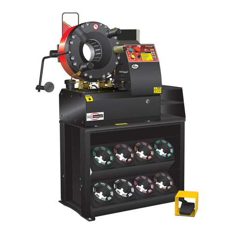
Gates GC32TSi Guide

1
GC32TSi SAFETY AND OPERATION MANUAL
GC32TSi CRIMPER
SAFETY AND OPERATION MANUAL
GC32TSI
Product Number: 7480-7004
Part Number: 78827

CRIMPER DETAILS
YOUR CRIMPER DETAILS
SERIAL NUMBER
(LOCATED ON REAR RESERVOIR BASE)
DATE OF PURCHASE
CRIMPER SPECIFICATIONS
DYNAMIC
Nom. Size (Hydraulic Hose Size) 2 inches
Die Set Type 32 series
Crimping Range (inch with Std. Die Set) 1/4 to 2 inches
Crimping Range (inch with Optional Dies) 3/16 to 2½ inches
Radial Swaging Force 4100 kN / 418 tonne
Cycle Speed (Full Stroke-Complete Cycle) 16 seconds
PHYSICAL
Dimensions (Plan inch x inch x Height inch) 27 x 20 x 30
Weight (Without Dies & Oil lbs) 660 lbs / 295 kg
Shipping Space 47,120 cubic inches
Shipping Weight 787 lbs / 358 kg
Crate Size (Plan in x in x Height in). 40 x 31 x 38
ELECTRICAL
Supply (Voltage / Current / Frequency )
230 V
16 A
50 Hz to 60 Hz
Plug Type (North America) NEMA L6 20
Phase Single Phase
Power 4.0 kW / 6.0 HP
HYDRAULIC
Rated Pressure 4300 PSI
Reservoir Capacity 8 US Gallons
Filtration 10 um
MAINTENANCE Grease Specification Tungsten Disulphide
GC32TSi Safety and Operating Manual-A4.indd 2 1/11/17 12:36 PM

GC®32TSi™ Safety and Operation Manual | 1
TABLE OF CONTENTS
Crimper Safety............................................................................................................................................................................. 2
Location Preparation ................................................................................................................................................................. 3
Box Contents................................................................................................................................................................................. 4
Crimper Installation .................................................................................................................................................................... 5
Moving the Crimper......................................................................................................................................................... 6
Electrical............................................................................................................................................................................ 8
Ergonomics ....................................................................................................................................................................... 8
Operating Instructions
Power Up............................................................................................................................................................................ 9
eCrimp.............................................................................................................................................................................. 10
Verify Crimp..................................................................................................................................................................... 12
Hose Preparation...................................................................................................................................................................... 13
Load Crimper Dies ......................................................................................................................................................... 14
Crimp Aasembly ............................................................................................................................................................ 15
Unload Die Set................................................................................................................................................................ 17
Calibration .................................................................................................................................................................................. 17
Periodic Maintenance.............................................................................................................................................................. 18
Lubrication .......................................................................................................................................................................18
Torque Bolts.....................................................................................................................................................................18
Foam Filler Pads .............................................................................................................................................................18
Check Oil Level.................................................................................................................................................................19
Add Oil................................................................................................................................................................................19
Oil & Filter Change..........................................................................................................................................................19
Replace or Add Oil...........................................................................................................................................................19
Tooling ......................................................................................................................................................................................... 20
Troubleshooting ........................................................................................................................................................................ 22
Operating Instructions
Using the Gates Insertion Tool.....................................................................................................................................23
Warranty ..................................................................................................................................................................................... 24
GC32TSi Safety and Operating Manual-A4.indd 1 1/11/17 12:36 PM

2 | Gates Corporation
CRIMPER SAFETY
An incorrect hose assembly can rupture or blow apart in use, resulting in serious injury, death, or
property damage.
REMEMBER: Others depend on you to make correct assemblies.
Hose Assembly Fabrication.
›Component Inspection: Before creating an assembly be sure to inspect all components to
be sure they are correct product, cut correctly, and do not have any visually identifiable
defects.
›Couplings (compatibility): Hose fitting components from one manufacturer are not usually
compatible with fitting components supplied by another manufacturer. Never mix and
match hose couplings from different manufacturers unless approved by both parties.
›Hose assembly equipment (crimpers): Hoses and fittings from one manufacturer should
not generally be assembled with the equipment of another manufacturer.
NOTE: Gates recommends only those hose and coupling combinations specified in the Gates
Hydraulic Product catalogs. Gates disclaims any liability for any hose assemblies which have not been
produced in conformance with Gates assembly recommendations.
WARNING
!
Carefully read and understand the following warnings before operating this crimper.
FOR SAFETY’S SAKE USE THIS MACHINE ONLY IF YOU:
1. Receive hands-on TRAINING with this Gates crimper and assemblies.
2. Follow current GATES OPERATING MANUAL and CRIMP DATA for the GC32TSi crimper.
3. Use only NEW (UNUSED GATES) hose and fittings.
4. Wear SAFETY GLASSES.
5. Keep hands clear of moving parts.
WARNING
GC32TSi Safety and Operating Manual-A4.indd 2 1/11/17 12:36 PM
GC®32TSi™ Safety and Operation Manual | 3
LOCATION PREPARATION
SELECT LOCATION
Before you unpack the crimper, decide where it will go. Choose
a location where the operator can have access to the front, rear
and left side. Bent (e.g. 90 degree) couplings must be loaded from
the rear of the crimper head. Note there is an indentation in the
front flange is designed to accommodate these couplings during
crimping.
UNPACK OPTIONAL STAND CARTON (if purchased)
Uncrate stand (Part No. 78829, Product No. 7480-7002) and
unbolt from pallet. To attach tool shelf, remove Allen head bolts
from top of stand, position shelf and replace bolts.
Position stand to allow front, left side, and rear access to the
crimper. Stand should be bolted to floor.
ERGONOMIC STAND ADJUSTMENT
Adjust height of stand to suit hose feed method (i.e. bench fed or
hand fed).
If hose is hand fed, the bottom of the hose should be level with the
operator’s elbows when standing upright. Operator should have a
straight back during crimping to avoid injury from handling heavy
hose assemblies. It is approximately twenty inches from the top of
the stand to the center of the crimper head. If this is comfortable,
no adjustment is needed. If this is too high or too low, adjust height
of stand by setting stand on its side and removing leg bolts. Raise
or lower legs to comfortable height. Replace bolts and tighten. If
optional die racks were purchased, place in bottom of stand or
hang on the wall.
If using the stand, bolt crimper using the four 6mm (1/4") Allen
head bolts (included) through predrilled holes. If mounting to a
bench, drill four 1/2" holes aligning with holes in crimper and bolt
together. Proper crimping height is approximately 32".
GC32TSi Safety and Operating Manual-A4.indd 3 1/11/17 12:36 PM

4 | Gates Corporation
BOX CONTENTS
GC32-TSi crimper
Tube of Tungsten Disulphide grease with brush
Calipers
Calibration tool
Foot Pedal
Quick Change Tool
Hydraulic Oil (in reservoir)
Air Breather (must be fitted at customers location)
Stand, dies and rack are ordered separately.
CALIBRATION
TOOL
TUNGSTEN
DISULPHIDE
GREASE
QUICK CHANGE
TOOL
FOOT PEDAL
CALIPERS
AIR
BREATHER
GC32-TSi
CRIMPER
GC32TSi Safety and Operating Manual-A4.indd 4 1/11/17 12:37 PM

GC®32TSi™ Safety and Operation Manual | 5
CRIMPER INSTALLATION
The crimper is top heavy and weighs 660 lbs (300kg)
›Follow the correct set-up procedure as shown in this manual
›Failure to follow proper procedures can create risk of severe injury and/or damage to the crimper
›DO NOT lift crimper by head. Use lifting anchors on crimper base.
Assemble the optional crimper stand, if using. The crimper stand
MUST be secured to the floor.
STORE AND INSTALL DIE SETS
Using the Quick Change Tool (QCT), load dies into the front and/or
back of stand, in optional rack or store in plastic shipping tubs.
Remove the plastic wrapping from the outside of the box.
Remove the staples from the bottom and top of carton with a
screwdriver and pliers.
Slit the tape on the top of the carton with a sharp knife, then open
the lid and remove the wooden side supports.
GC32TSi Safety and Operating Manual-A4.indd 5 1/11/17 12:37 PM
6 | Gates Corporation
Lift off the carton.
Note voltage and frequency on the name plate located on the back
of the tank. Ensure it is suitable for this location.
Using a 5/8 (16mm) wrench remove the four mounting bolts
Adjust the ratchet handle to rotate the control box out
approx 15 degrees, retighten the handle. Remove control
box power cord. Position the first sling between the control
box and the electric motor as per the photo so that the straps
clear the control box. Ensure the other half of the sling does
not cause excessive pressure on the motor juntion box.
Position the second sling in front and behind the crimper head as
per the photo.
INSTALLATION: SAFELY MOVING CRIMPER
GC32TSi Safety and Operating Manual-A4.indd 6 1/11/17 12:37 PM
GC®32TSi™ Safety and Operation Manual | 7
Position the lifting device over the center of the crimper and
attach the slings then slowly raise the crimper and place it on a
suitable table.
Fit 5/8" (M10) bolts, nut and washers into pre-drilled holes and
tighten.
Secure the crimper to bench. If using the optional stand, bolt
crimper using the four 6mm Allen head bolts (included) through
predrilled holes. If mounting to a bench, drill four ½" holes aligning
with holes in crimper and bolt together.
Remove the slings and store.
Oil reservoir is shipped full. Remove plug and replace with
breather cap, store plug. Always ship crimper with plug
installed to avoid spillage of hydraulic fluid or contamination
of breather element. Check the sight glass to make sure oil
level is half way with the head fully retracted (open).
INSTALLATION: SAFELY MOVING CRIMPER
INCORRECT LIFTING
DO NOT lift crimper by head as this will cause damage to the crimper.
Use lifting anchors on crimper base.
GC32TSi Safety and Operating Manual-A4.indd 7 1/11/17 12:37 PM

8 | Gates Corporation
CRIMPER INSTALLATION
Consult with a qualified electrician for the correct plug and outlet for your power supply.
Incorrect electrical connection can cause damage to component or an electrical hazard
for personnel. The crimper is shipped with a NEMA L6 20 cable; modifying this cable voids
your warranty.
ELECTRICAL
Connect the provided 220 VCA single phase cord assembly with
HBL 2321 250 HVAC 20 amp twist lock plug to your crimping
machine.
Connect your region specific electric cable to a suitable power
supply socket of at least 16A.
ERGONOMICS
INSTALL FOOT PEDAL
This crimper can also be activated by using a foot pedal. The
protective metal case surrounding the pedal will avoid accidental
activation. Install foot pedal by plugging it into the lower right side
of control panel next to the power switch.
CONFIGURE CONTROL PANEL IN COMFORTABLE WORKING
POSITION
The control panel can be rotated to a position that is more
accessible depending on where the operator is working. Loosening
the locking handle located to the left of the control box will allow
the box panel to pivot approximately 30 degrees left. The control
panel can then be pivoted by loosening its locking handle, located
above the control box and below the control panel, on the right
hand side.
Connect panel power cable to control panel.
GC32TSi Safety and Operating Manual-A4.indd 8 1/11/17 12:37 PM

GC®32TSi™ Safety and Operation Manual | 9
OPERATING INSTRUCTIONS
To Prevent Serious Injury:
›Keep away from all moving parts! If bodily contact should occur with a moving part,
immediately release CRIMP button, foot pedal.
›Do not operate crimper with hand, fingers, or any body part in crimper mouth.
›Keep additional personnel away from crimper while operating.
POWER UP
TURN POWER SWITCH ON
Ensure the crimper is properly connected to correct power supply.
Turn the power switch on. The power switch can be found on the
right of the control box.
TURN CONTROL PANEL ON
The switch is located at the top left corner of the panel.
NOTE: Power must be turned on on both the crimper and the
panel. Turning power off on crimper will not turn power off on
panel. The panel will continue to charge when main switch is off.
Remove plug from wall outlet to remove power from panel.
When you have power to machine and panel, the main menu
screen will appear. An assembly must be selected for the machine
to function.
QUICK START: Press E-Crimp
GC32TSi Safety and Operating Manual-A4.indd 9 1/11/17 12:37 PM

10 | Gates Corporation
OPERATING INSTRUCTIONS
ECRIMP
You will be directed to ‘Favorites’ each time you open
E-Crimp. Favorites is an area where you can save a
collection of your most popular hose assemblies. A special
folder will be created for each hose type you save. The
8G2-8G was added to 'Favorites' at the factory and is used
for the example below.
There are tutorials in the Operator Help area to guide you
through more advanced operation. Here we will show
you how to set-up for your first assembly. The screen will
automatically go to ‘Favorites’, there is a ‘G2’ assembly
folder.
Under ‘Favorites’, select the saved E-Crimp favorite folder
‘G2’.
In the G2 folder we have loaded 8G2-8G hose assembly. This
assembly will also be used to qualify the calibration of the
machine. This selection has a final COD of 1.050”.
Select the G2 assembly to proceed to the Crimp Summary.
This will load the specific hose assembly components, hose
type, hose size, ferrule/stem type and specify the die set to
be used. NOTE the die set displayed as you will need to load
this die set in the machine.
You can compare the summary with the details provided.
Once you have confirmed this assembly details, press
‘CRIMP’ to load the settings to the Crimper app.
The new setting will be loaded to the crimper app. If the
correct Die Set is already loaded, ‘Ready to Crimp’ will be
displayed.
GC32TSi Safety and Operating Manual-A4.indd 10 1/11/17 12:37 PM

GC®32TSi™ Safety and Operation Manual | 11
OPERATING INSTRUCTIONS
If a new Die Set needs to be loaded, the E-Crimp application
will advise that you that a Die Change is required. Press and
hold ‘Reposition Head’ until the crimper head reaches the
die change position.
E-Crimp will advise when the ‘Die Change Position’ has been
reached and the new die set can be inserted.
Load correct Die Set in the machine using the QCT, then
press ‘Done’. ‘Ready to Crimp’ will be displayed.
Place the G2 assembly as detailed in the Crimper to make
your first hose, or place just the ferrule to qualify calibration,
then press the blue ‘Crimp’ button or use the Foot Pedal.
When you see the message ‘Pinch Decompression Mode
Finished’, the crimping process is complete.
GC32TSi Safety and Operating Manual-A4.indd 11 1/11/17 12:37 PM

12 | Gates Corporation
OPERATING INSTRUCTIONS
Press the yellow 'Retract' button and remove the ferrule.
VERIFY CRIMP
Measure the ferrule using a digital caliper to confirm the
crimp is within tolerance
When measuring the crimp outer-diameter, always measure
3 times around the fitting, avoiding the ridges.
Take an average of the 3 measurements.
›The measured crimp diameter must be within +/- 0.010"
of the published crimp diameter . NOTE: DO NOT measure
on top of part number stamps or ridges.
›Should the actual crimp diameter not be within specified
crimp tolerance, the assembly MUST be discarded. If the
machine is not crimping product accurately, it may need to
be recalibrated. Refer to the calibration procedure.
Multiple Crimps
›When crimping multiple assemblies, check every
tenth crimp to ensure diameter is within the
acceptable range. (+0.010").
›Discard those outside the specified tolerance.
Protect the safety of people using your assemblies! Your measured crimp diameters MUST
be in tolerance range as listed in eCrimp.
Improperly made assemblies could result in coupling blow off at high pressure, risk of fire
and/or serious injury or death.
GC32TSi Safety and Operating Manual-A4.indd 12 1/11/17 12:37 PM

GC®32TSi™ Safety and Operation Manual | 13
OPERATING INSTRUCTIONS
New hose and end fittings (stem/ferrule) must be used when building a hose
assembly. Reusing any components will seriously affect performance and
could result in serious injury, death or property damage.
HOSE PREPARATION
Cut Hose
Cut hose to required length. Ensure hose is clean of debris to
avoid contamination of a hydraulic circuit.
The assembly process is different for two piece couplings
versus one piece couplings:
IF ASSEMBLY REQUIRES GLOBALSPIRAL™ (GS) TWO PIECE
COUPLINGS
1. Slide ferrule over hose end
2. Lubricate the first two or three serrations on stem with
lightweight oil.
3. Clamp stem in vise jaws on hex portion and push hose
onto stem until locking collar bottoms out against hose.
Hose should be flush against stem shoulder.
4. Hose and coupling are now ready for crimping.
IF ASSEMBLY REQUIRES MEGACRIMP® PRE-ASSEMBLED
(ONE PIECE) COUPLINGS
1. Place a visible mark on hose cover at the insertion
length shown in the crimp data manual, or by using
the MegaCrimp Hose Insertion tool, Part No.: 78017,
Product No.: 7482-1342.
2. Insert coupling into hose until the mark lines up with
coupling ferrule end.
3. Hose and coupling are now ready for crimping.
Gates designed MegaCrimp couplings for easy insertion. You
can feel them "hit bottom" when the hose is fully inserted. Once
the hose is inserted it stays put, so MegaCrimp couplings won't
fall off during the cirmping process.
GC32TSi Safety and Operating Manual-A4.indd 13 1/11/17 12:37 PM

14 | Gates Corporation
OPERATING INSTRUCTIONS
LOAD CRIMPER DIES
Review eCrimp Summary
The eCrimp application indicated the correct die set to be used for
the specified hose/coupling combination.
Locate Correct Die Set
This may be in the optional stand, or in the die container.
Load Die Set
Load Die Set with Gates Quick Change Tool (QCT).
Align Dies
Align die finger dovetails, between the die retention plates, with die
shoe receptacles in crimper head.
Insert QCT
Insert the QCT until it bottoms out on the die shoe surface. The die
is then set (red aligns with black on decal).
Twist QCT
Release the QCT by pushing the handle in to disengage dies, then
twisting to the left, or counterclockwise, until die fingers are
disengaged. (Red aligns with red on decal)
Withdraw QCT
1
2
3
4
5
6
GC32TSi Safety and Operating Manual-A4.indd 14 1/11/17 12:37 PM

GC®32TSi™ Safety and Operation Manual | 15
OPERATING INSTRUCTIONS
To Prevent Serious Injury:
›Keep away from all moving parts! If bodily contact should occur
with a moving part, immediately release CRIMP button, foot pedal or
emergency stop.
›Do not operate crimper with hand, fingers, or any body part in crimper
head.
›Keep additional personnel away from crimper while operating.
CRIMP ASSEMBLY
Precursors
The hose has been prepared, the machine is set, and the correct
dies are loaded in the crimper.
Select Crimper Application.
Insert Assembly Into Crimper Head
›You may need to press and hold the yellow retract button
to ensure sufficient clearance for assembly.
›Insert straight assemblies through either front or back of
crimper head. If a bent tube is being crimped, it must be
crimped by loading assembly from the rear of crimper.
›Adjust front of ferrule approximately 1/8" from edge of die
shoe.
›IMPORTANT: For GS couplings make sure top of ferrule
rests against hex or round shoulder of locking collar to
ensure proper crimp.
GC32TSi Safety and Operating Manual-A4.indd 15 1/11/17 12:37 PM

16 | Gates Corporation
CRIMP ASSEMBLY
BEGIN the CRIMP. Push the Blue Crimp Button, or depress foot
pedal.
NOTE: CRIMP button and foot pedal operate on a "dead man"
control while in crimp mode. It only operates as long as you press
the CRIMP button or hold foot pedal down. It stops immediately
when switch is released. If using only the foot pedal, when
crimp setting is reached, crimper will momentarily pause before
automatically retracting.
Note: When crimping a two-piece coupling (e.g., GS, GSP) as
soon as the die fingers contact the ferrule, pull slightly on the
hose assembly. That ensures the ferrule-locking collar is properly
located over the stem locking collar.
Crimper will close to the position corresponding to the settings
chosen. Once it reaches that position, the crimper stops
automatically as part of the pinch decompression feature.
To remove crimped assembly, press and hold yellow retract button
until crimper stops. The Crimper will automatically retract with foot
pedal. Note: Crimper will fully retract every 10th crimp as part of
automatic greasing.
Crimp is now complete. Remove assembly and verify that crimp is
within tolerance.
Set the retract timer by sliding the button with your finger.
OPERATING INSTRUCTIONS
GC32TSi Safety and Operating Manual-A4.indd 16 1/11/17 12:37 PM

GC®32TSi™ Safety and Operation Manual | 17
OPERATING INSTRUCTIONS
UNLOAD DIE SET
Retract Head
Fully retract crimper head, using yellow retract button within
crimper application.
Insert QCT
Insert the Quick Change Tool (QCT) until it bottoms out on the die
shoe surface.
Twist QCT
Twist the QCT clockwise until die fingers are engaged and withdraw
QCT. This will pull the die fingers out of the crimper head
Place Dies
Place die fingers back into storage receptacle and press
downward.
Twist QCT
Twist the QCT handle counterclockwise to unload die fingers.
Withdraw QCT
7
6
5
4
3
2
CALIBRATION PROCEDURE
Refer to calibration procedure included on the tablet and GC32TSi support website.
GC32TSi Safety and Operating Manual-A4.indd 17 1/11/17 12:37 PM

18 | Gates Corporation
PERIODIC MAINTENANCE
This crimper requires minimal maintenance. However, the following practices are recommended
to ensure maximum reliability and service.
LUBRICATION
Periodically Redistribute grease build up.
The crimper is designed to automatically redistribute some grease
around the cone.
Grease will also build up over time as some is pushed out. This can
be redistributed with a brush periodically.
At the rear of the crimper, use a grease brush to distribute grease
inward that has been pushed out by crimping action. To properly
care for your machine this should be done every 100 crimps, or
whenever a significant amount of grease has been pushed out of
circulation.
Periodically apply fresh Tungsten Disulphide grease.
If cone becomes shiny, use a brush to apply a tablespoon of fresh
Tungsten Disulphide grease around the cone. The machine comes
with Tungsten Disulphide grease, which is far more effective
than alternatives. Do not use alternative grease, as this will
contaminate the grease on your machine. Using alternatives will
void warranty.
TORQUE BOLTS
Periodically check torque bolts.
Check torque on flange bolts every 6 months. Torque settings is
330 Nm, or 243 ftlb.
FOAM FILLER PADS
Periodically inspect filler pads.
The crimper will not retract if foam filler pads are clogged with
grease, in which case the foam filler pads need to be replaced.
Inspect filler pads every 1000 crimp cycles. Foam should return to
original shape after compression. If foam pad does not fill space
between die shoes, order new set and install. (product number)
GC32TSi Safety and Operating Manual-A4.indd 18 1/11/17 12:37 PM
This manual suits for next models
1
Table of contents
Other Gates Crimping Tools manuals

Gates
Gates GC16XD Installation manual

Gates
Gates GC32FLEX Guide

Gates
Gates GC20 Instruction Manual

Gates
Gates GC16XD Installation manual

Gates
Gates GC96 User manual

Gates
Gates MC3001 Use and care manual

Gates
Gates Power Crimp 707 Installation manual

Gates
Gates GC32-XD User manual

Gates
Gates MobileCrimp 4-20 Installation manual

Gates
Gates MCX50 Use and care manual
Popular Crimping Tools manuals by other brands

Tyco Electronics
Tyco Electronics 408-10050 instruction sheet

molex
molex 63823-7570 Specification sheet

HRS
HRS HT601/TM21P-88P operating instructions

HARTING
HARTING 09 99 000 0119 Operation manual

Tyco Electronics
Tyco Electronics 90015 instruction sheet

TE Connectivity
TE Connectivity 2378724-1 instruction sheet