Gates GC32-XD User manual

CRIMP DATA AND DIES
GC32-XD™ & FLEX & GC96™ - POWER CRIMP®707 & SC32™ -
GC16XD-MOBILECRIMP®4-20 DD & PS - POWER STEERING - SWAGING
VERSION 186 - 2020-11-24
EDITION 2021

GENERAL INFORMATION
HOSE ASSEMBLY GUIDE ..........................................2-7
POLAR SEAL I CRIMP DATA.......................................... 8
POWER STEERING CRIMP DATA ...................................... 9
GATES GLOBAL PART NUMBERING SYSTEM ........................... 10
SWAGING INFORMATION
SWAGING PROCEDURES ....................................... 11-12
TH7 SWAGE DATA .............................................. 13
C14 SWAGE DATA ........................................... 15-19
GC32-XD™ & FLEX & GC96™ WITH SPACER DIES
GC32-XD & FLEX CRIMP DATA................................... 20-42
GC32-XD & FLEX LIFEGUARD™ CRIMP DATA ....................... 43-45
GC96 (WITH SPACER DIES) CRIMP DATA........................... 46-67
CALIBRATION & ADJUSTMENT PROCEDURES ....................... 68-72
CRIMP DIES AND TOOLING......................................... 73
CLAMP COLLAR CRIMPING INSTRUCTIONS ........................... 74
POWER CRIMP®707 & SC32™
POWER CRIMP®707/SC32™ CRIMPERS ............................. 75
PC 707, 700 SERIES (8 FINGER) DIES CRIMP DATA.................. 76-98
PC707 LIFEGUARD CRIMP DATA ................................99-100
SC32 CRIMP DATA ..........................................101-122
SC32 LIFEGUARD™ CRIMP DATA ...............................123-124
CALIBRATION & ADJUSTMENT PROCEDURES .....................125-126
CRIMP DIES AND TOOLING........................................127
CLAMP COLLAR CRIMPING INSTRUCTIONS ..........................128
GC16XD
GC16XD CRIMP DATA ........................................129-133
GC16XD CALIBRATION PROCEDURE ............................134-135
MOBILECRIMP®4-20 DD & PS
MOBILECRIMP®4-20 CRIMPERS...................................136
MC 4-20 DD CRIMP DATA.....................................137-154
MC 4-20 PS CRIMP DATA .....................................155-172
CALIBRATION & ADJUSTMENT PROCEDURES .........................173
CRIMP TOOLING ................................................174
CLAMP COLLAR CRIMPING INSTRUCTIONS ..........................175
POWER STEERING MALE FLARELESS ASSEMBLY INSTRUCTIONS
POWER STEERING ASSEMBLY INSTRUCTIONS ....................176-177
NOTE: CRIMP DATA FOR OMNICRIMP®21, POWER CRIMP®3000B &
POWER CRIMP®2001 IS LOCATED IN ECRIMP. DOWNLOAD THE ECRIMP
APP OR GO TO WWW.GATES.COM/ECRIMP.
1
DOWNLOAD THE ECRIMP APP OR GO TO WWW.GATES.COM/ECRIMP
POWER STEERING MC 4-20 DD & PS GC16XD PC707/SC32 GC32-XD/FLEX
GC96 SWAGING GENERAL
CRIMP DATA + DIES
GATES
HOSE ASSEMBLY
GUIDE
Wear the proper personal protection equipment when working
with fabrication equipment to make assemblies. To find the
hose use the STAMPED process to determine which product is
needed, then identify the terminations of the existing assembly
by their physical characteristics and dimensions.
Once the hose has been determined select the appropriate
coupling by looking through the crimp data to find what stem
and ferrule types may be used. Use the stem and ferrule with the
termination information to determine the best coupling to use.
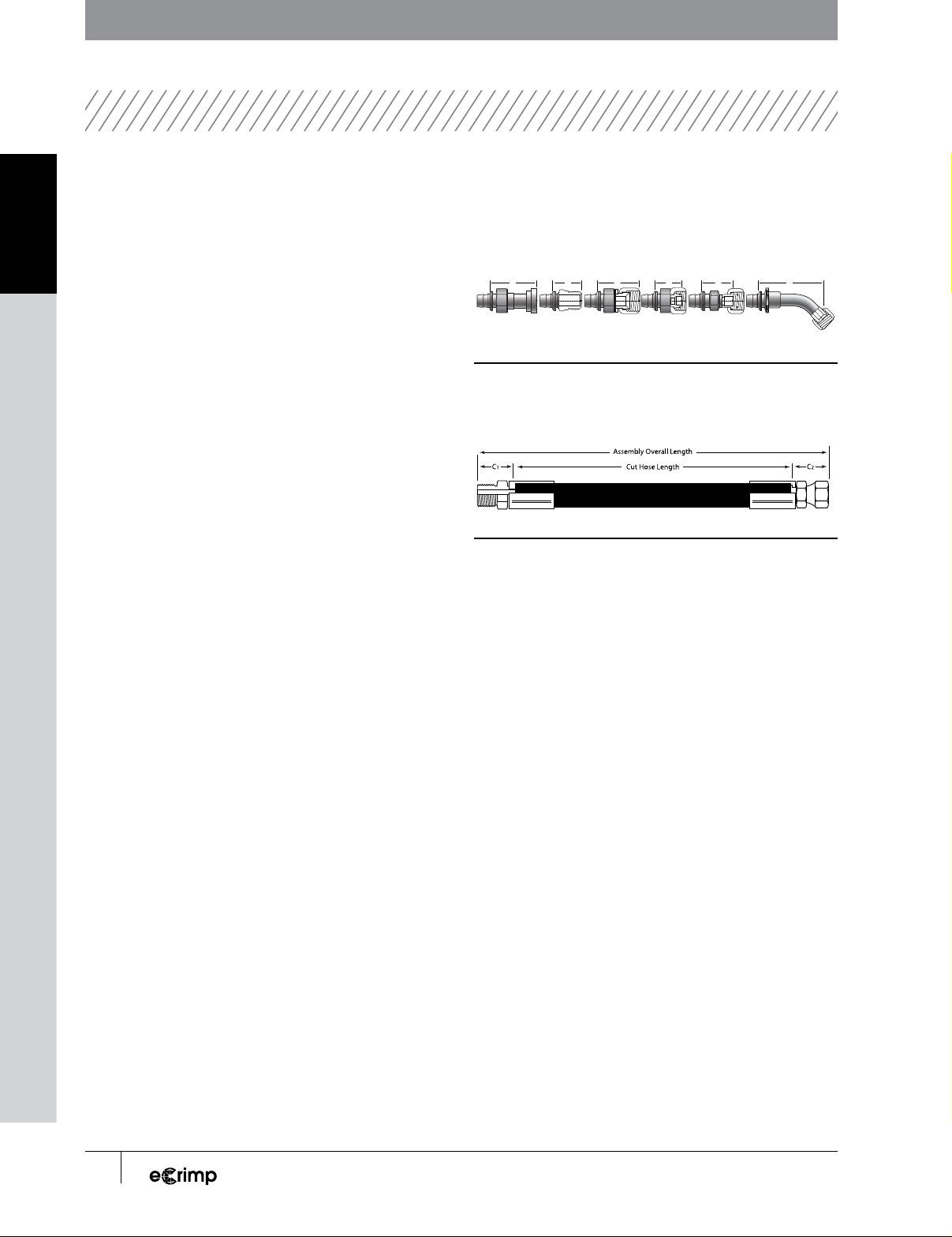
DETERMINE THE CUT LENGTH OF THE HOSE
To determine the cut length of the hose, first find the overall length
of the hose assembly. The point at which the ends of the assembly
are measured will depend on the construction of the couplings.
All flanges are measured from the center point of the flange
face, Figure 1D. All straight male couplings are measured from
the seal face, Figure 1E. Straight female couplings with SAE,
JIC (FJX), NPSM (FPX), JIS and Komatsu specifications are
measured from the farthest point which the nut will extend,
Figure 1F. Straight female couplings with DIN, BSP, GAZ
specifications are measured from the face of the seal, Figure
1G. Straight Flat Face O-ring seal (FFOR) couplings are always
measured from the face of the seal, Figure 1H. All bent and
block couplings (male and female) are measured from the point
at which the center line of the coupling intersects the seal face,
Figure 1I.
Once the overall length of the assembly is determined the cut
length of the hose will be the overall length of the assembly
minus the “C” length of each coupling, as shown in Figure 2. “C”
lengths are available in the Gates Hydraulic catalog.
CUTTING THE HOSE
Once the cut length of the hose has been determined it is time
to cut the hose section to length. Rubber hydraulic hoses should
be cut with a hose cutting saw, equipped with a scalloped,
serrated or abrasive blade.
C C
IHGFED
CCC C
FIGURE 1
From left to right: Measurement of D) flange, E) straight male, F) US spec., G)
International spec., H) FFOR and I) bent (elbow) couplings.
FIGURE 2
A hose assembly.
A serrated blade will produce the cleanest cut, but should only
be used for cutting hose with fabric, textile, wire braid or spiral
wire reinforcement. Usually serrated blades should not be
used for cutting helical wire embedded hose. If the hose saw
is equipped with a blade cooling mechanism, then a serrated
blade may be used to cut spiral wire hose. Serrated saw blades
may be flipped and also re-sharpened to extend their life.
An abrasive composite blade is capable of cutting all types of
hose, but will product much more smoke and dust than serrated
blades and leave more contamination in the hose that will need
to be removed so it does not get into the hydraulic system once
installed. Abrasive composite blades will wear down over time
and must be replaced when it cannot cut fully through a hose.
Use the hose bending fixtures on the hose cutting saw in order
to prevent blade binding and they will help achieve straight
consistent cuts. To meet SAE and ISO standards the hose cut
must be within 5° of perpendicular, on 1” hose this is less than
3/32”, Figure 3.
PTFE and thermoplastic hydraulic hoses may be cut cleanly with
a shear. Once the cut is made the tube must be deburred using
a sharp knife.
2DOWNLOAD THE ECRIMP APP OR GO TO WWW.GATES.COM/ECRIMP
GENERAL SWAGING GC32-XD/FLEX
GC96 PC707/SC32 GC16XD MC 4-20 DD & PS POWER STEERING
GATES
HOSE ASSEMBLY GUIDE

FIGURE 3
Hose cut length tolerance
LENGTH TOLERANCE
(PLUS OR MINUS) MM
Up to 300 mm, included 3
Over 300 mm through 450 mm, included 5
Over 450 mm through 900 mm, included 7
Over 900 mm + 1%(1)
(1) Measured to nearest whole milimeter.
FIGURE 4
SAE J517 assembly length tolerance.
When cutting any hose it is important to understand the amount
of variation in length which is appropriate. The SAE provides the
guidelines shown in Figure 4. Generally it is best to have a small
amount of extra hose in an assembly, however even a small
amount of extra length can be very problematic especially for
short hoses.
SKIVING AND BUFFING
Skiving or buffing should only be done as recommended in the
crimp specifications, most Gates products no longer require
skiving or buffing for installation.
Skiving is the removal of the hose cover down to the
reinforcement, Figure 5. Skiving may be done with a wire
abrasion wheel or a hand skiving tool. Careful attention
should be paid to ensure that skive length is correct and the
reinforcement has not been damaged in the skiving process.
Buffing is the removal of some hose cover material while still
leaving material covering the hose reinforcement. This is done
both for wire and non-wire reinforced hose construction, and
when necessary for coupling installation. A grinding wheel is
used for buffing for consistency and to help prevent damage to
the reinforcement.
FIGURE 5
Picture of a skived hose end.
COUPLING INSTALLATION
Once the hose has been completely prepared dry fit all of the
couplings to ensure that the assembly length and orientation is
correct in the final assembly.
When two bent couplings are used on an assembly orientation
is critical, per SAE specifications the couplings must be within
±3° of desired. In order to achieve this begin by orienting the
coupling on the far end of the hose vertically downward, then
measure the orientation clockwise from this position for the
near end. Once positioned place a witness mark on the hose
and coupling. For hydraulic hoses the layline makes an ideal
way to confirm the proper orientation of the couplings.
Bear in mind that during the crimping process the assembly
will grow slightly due to compression of the ferrule and hose.
For assemblies which are very critical in length, compare
measurements before and after crimping on end of the assembly
so that compensation may be made for the change in length.
3
DOWNLOAD THE ECRIMP APP OR GO TO WWW.GATES.COM/ECRIMP
POWER STEERING MC 4-20 DD & PS GC16XD PC707/SC32 GC32-XD/FLEX
GC96 SWAGING GENERAL
GATES HOSE ASSEMBLY GUIDE

FIGURE 6
Correct crimper usage.
CRIMPING
There are several different crimping procedures described,
depending on the coupling which is to be applied. No matter
what style of crimp is used the same safety rules apply.
■Assemblies must be fabricated only from NEW
(Unused) Gates hose and couplings.
■Always consult the most current crimp data available
to check the crimp specifications and machine
settings.
■Load the recommended die set into the crimper.
Properly lubricate the crimper dies, but do not
lubricate the bore of the die.
■Always wear safety glasses
■Keep hands away from moving parts of the crimper.
■For any questions consult the crimper operation
manual or Gates technical support.
■All settings are approximate! Variation due to
tolerances and wear may exist, always measure the
finished crimp diameter.
FULL LENGTH CRIMP ONE-PIECE COUPLINGS (G, P,
GSM, MGS)
When installing 1 piece couplings it is recommended that the
hose is marked with the insertion depth from each cut end. This
way there is a mark to verify the coupling has been fully inserted
into the hose.
These types of couplings require a full length crimp, shown in
Figure 7. In order to form the full length crimp the edge of the
coupling should be inserted into the die approximately 1/8”
past the die edge. This will ensure that the entire ferrule is
crimped, without a bubble near one end.
CRIMP
FULL
LENGTH
CRIMP
FULL
LENGTH
FIGURE 7
Full Length Crimp.
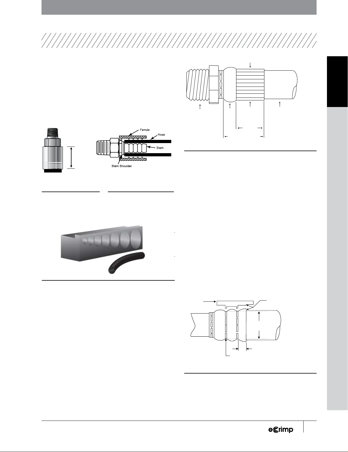
FULL LENGTH CRIMP TWO-PIECE COUPLINGS (GS,
GSP, PC, B & S STAINLESS STEEL)
When installing 2 piece couplings (with separate stem and
ferrule) place the ferrule onto the cut hose then insert the stem
into the hose. If stem insertion is very difficult the serrations
may be lubricated with light oil, and if necessary the coupling
restrained in the jaws of a vice. Be sure that the hose is fully
inserted onto the stem by moving the ferrule and visually
inspecting. When crimped the ferrule must be latched into the
stem shoulder, see figure 9.
These types of couplings require a full length crimp, see Figure
8. In order to form the full length crimp the edge of the coupling
should be inserted into the die approximately 1/8” past the die
edge. This will ensure that the entire ferrule is crimped, without
a bubble near one end. Before making the crimp be sure ferrule
is engaged in the stem latching collar.
Incorrect Correct
4DOWNLOAD THE ECRIMP APP OR GO TO WWW.GATES.COM/ECRIMP
GENERAL SWAGING GC32-XD/FLEX
GC96 PC707/SC32 GC16XD MC 4-20 DD & PS POWER STEERING
GATES
HOSE ASSEMBLY GUIDE
MEGACRIMP INSERTION TOOL
This tool offers an easy way to confirm the right insertion depth
for MegaCrimp, see Figure 10. To use, simply insert the hose
into its proper slot indicated by dash size, push it all the way in,
check for square cut (maximum allowable angle of cut is five
degrees), then mark the insertion depth on the hose.
CRIMP
FULL
LENGTH
CRIMP
FULL
LENGTH
FIGURE 10
Insertion tool
PARTIAL LENGTH CRIMP ONE-PIECE COUPLING (GLX)
When installing 1 piece couplings it is recommended that the
hose is marked with the insertion depth from each cut end. This
way there is a mark to verify the coupling has been fully inserted
into the hose.
When forming a GLX crimp only the tail end of the coupling is
crimped. DO NOT crimp the full length of the ferrule. In order to
achieve the proper crimp length, mark this point onto the ferrule,
and only insert the ferrule in the dies up to the mark, bear in mind
the tolerance on the crimp length is ± 0.030 inches. See Figure 11.
Measure
Crimp Here Hose
Crimp
Length
Insertion Length
Coupling
Termination
Bell
FIGURE 11
GLX coupling crimp
BUBBLE CRIMP ONE-PIECE COUPLING (GL)
When installing 1 piece couplings it is recommended that the
hose is marked with the insertion depth from each cut end. This
way there is a mark to verify the coupling has been fully inserted
into the hose.
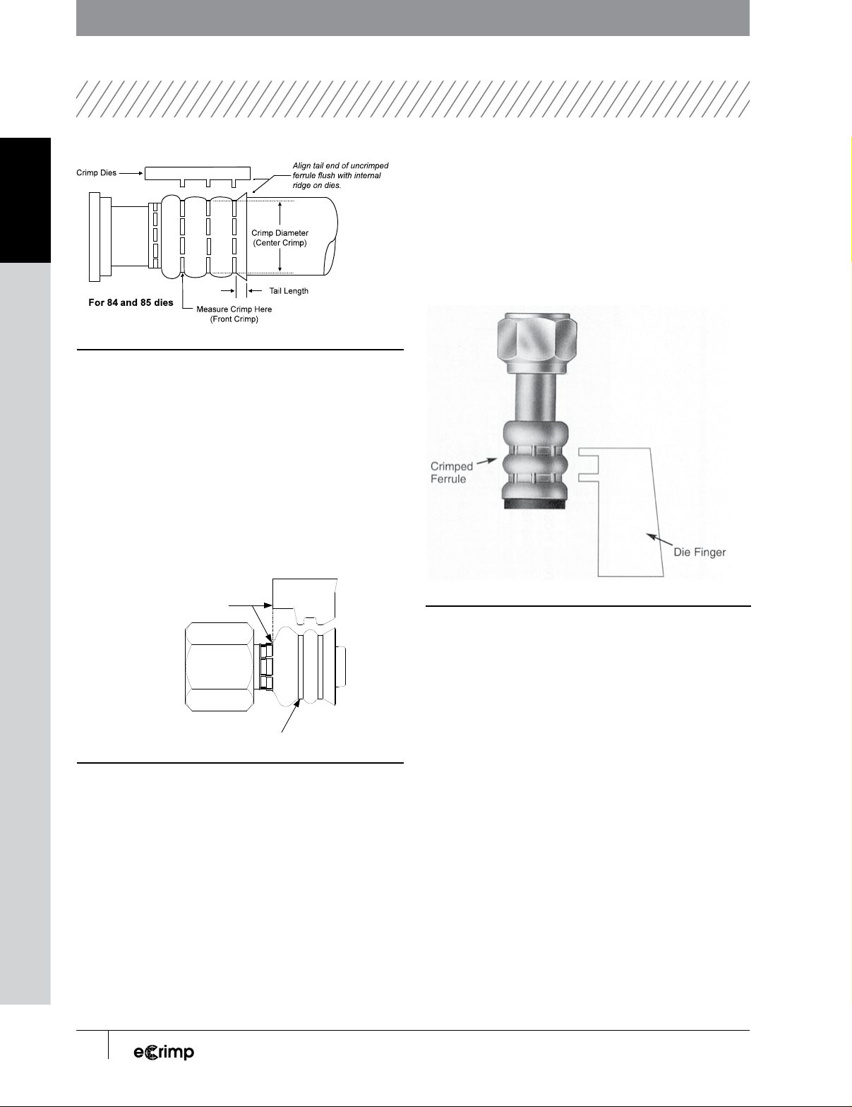
The GL coupling is only intended for low pressure service,
despite this it is still critical that the correct crimp outside
diameter and tail length are achieved in order to make a leak
free connection. The tolerance on the tail length of the crimp
is ± 0.100 inches. In order to achieve this tolerance: line the
coupling up with the ridges in the appropriate die, see Figures
12 and 13. Be sure the die fingers are all the way forward and
locked in place before crimping.
Align hose end of uncrimped
ferrule flush with internal
ridge on dies.
Crimp Dies
Crimp Diameter
(Front Crimp)
For 81, 82
and 83 dies
Tail Length
Measure Crimp Here
(Front Crimp)
FIGURE 12
2 band bubble crimp (dies 81, 82, and 83)
FIGURE 9
Proper 2 - piece coupling assembly
FIGURE 8
Full length crimp
5
DOWNLOAD THE ECRIMP APP OR GO TO WWW.GATES.COM/ECRIMP
POWER STEERING MC 4-20 DD & PS GC16XD PC707/SC32 GC32-XD/FLEX
GC96 SWAGING GENERAL
GATES HOSE ASSEMBLY GUIDE
* See Adjustment Procedures and Footnotes at the end of GC32-XD / GC96 section.
FIGURE 13
3 band bubble crimp (dies 84 and 85)
BUBBLE CRIMP ONE-PIECE COUPLING (GLP)
When installing 1 piece couplings it is recommended that the
hose is marked with the insertion depth from each cut end. This
way there is a mark to verify the coupling has been fully inserted
into the hose.
In order to achieve the correct crimp be sure to align the
coupling in the die as shown in Figure 14.
For Die Series:
71, 72, 73, 74 & 75
Measure Crimp Here
Align staked end of the ferrule
(fitting end) flush with the die face.
FIGURE 14
GLP alignment in crimper dies (die 71, 72, 73, 74, and 75)
AIR CONDITIONING COUPLINGS (ACA)
When crimping couplings for use with refrigerants be sure to
fully insert the hose into the coupling, a small hole is located on
the ferrule for visual confirmation of the hose insertion. No skive
or buff is needed or recommended for Polarseal hose and ACA
couplings. During crimping center the bands of the crimping die
on the ferrule as shown in Figure 15.
FIGURE 15
ACA coupling alignment
6DOWNLOAD THE ECRIMP APP OR GO TO WWW.GATES.COM/ECRIMP
GENERAL SWAGING GC32-XD/FLEX
GC96 PC707/SC32 GC16XD MC 4-20 DD & PS POWER STEERING
GATES
HOSE ASSEMBLY GUIDE

MEASURING THE CRIMP
When measuring a crimp position the caliper at the center of
the crimp length, or the appropriate band (as indicated in the
crimping diagrams), as shown in Figure 19. This is because
some taper may exist between the ends of the crimp.
Two Piece Couplings One Piece Couplings
FIGURE 19
Correct position to measure the crimp diameter along the length of the ferrule
The crimp diameter must always be measured on the flats
180° around the coupling, NOT on the protruding ridges,
as shown in Figure 20. For -8 and larger couplings place the
coupling against the rear of the caliper jaw and use the wide
flat area to measure. For -4 and -6 couplings use Notched end
of the Gates Stainless Steel Digital Calipers, place the small
flats at the end of the jaw against the flats on the coupling.
Always measure the crimp diameter from the depressed flat
area of the ferrule; DO NOT place the notches over protruding
ridges of the coupling.
Measuring -8 and larger couplings Measuring -4 and -6 couplings
FIGURE 20
Measuring the crimp outside diameter on the flats between the ribs
CRIMPER ADJUSTMENT
Should the actual crimp diameter not be within the tolerance
specified in the crimp data charts, check the calibration of the
crimper. If the calibration is correct a slight adjustment of the
crimper setting may be necessary.
To find the right adjustment to the setting, refer to your specific
crimper’s operating manual. When the setting has been calculated
and your new crimp is within the specified tolerance, make sure to
record your new approximate setting in the space provided in this
manual under “User’s actual setting” for future reference.
CLEANING THE HOSE
After the assembly has been successfully crimped it should be
cleaned in order to prevent contamination of the system onto which
it is being installed. This should be done with all assemblies since
particulates from the cutting or crimping process and other debris
may have entered the hose during fabrication.
Common methods of cleaning the hose assembly include
blowing through the assembly with shop air or a much more
effective method is the use of a shuttle. The Gates MegaClean
system uses foam projectiles to remove debris from hoses and
assemblies. For particularly difficult jobs multiple projectiles
may be fired from each end or a solvent such as water or
alcohol may be applied to the pellets.
7
DOWNLOAD THE ECRIMP APP OR GO TO WWW.GATES.COM/ECRIMP
POWER STEERING MC 4-20 DD & PS GC16XD PC707/SC32 GC32-XD/FLEX
GC96 SWAGING GENERAL
GATES HOSE ASSEMBLY GUIDE

* See Adjustment Procedures and Footnotes at the end of GC32-XD / GC96 section.
HOSE STEM CRIMP CRIMPER
DASH SIZE
1/16” DESCRIPTION SIZE
(IN)
WORKING PRES-
SURE
PSI
DASH SIZE
1/16" TYPE LENGTH
±0.03"
OD
±
0.01"
CRIMPER DIE SET APPROX.
SETTING*
USER
SETTING
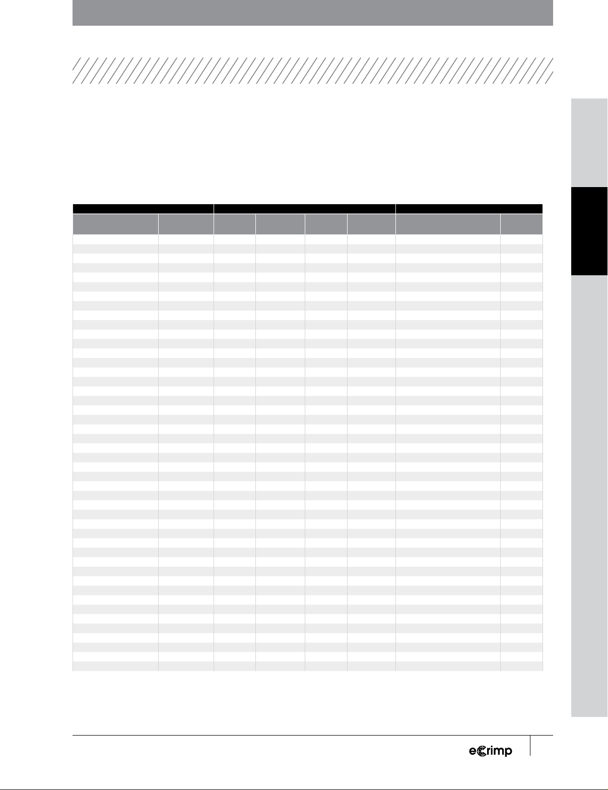
6 PolarSeal 0.3125 500 6 ACA BUBBLE 0.69 GC32/GC96 32-40 0.80
8 PolarSeal 0.4063 500 8 ACA BUBBLE 0.78 GC32/GC96 32-41 0.96
10 PolarSeal 0.5000 500 10 ACA BUBBLE 0.89 GC32/GC96 32-42 0.63
12 PolarSeal 0.6250 500 12 ACA BUBBLE 1.02 GC32/GC96 32-43 0.87
6 PolarSeal 0.3125 500 6 ACA BUBBLE 0.69 MC420DD MC40 180
8 PolarSeal 0.4063 500 8 ACA BUBBLE 0.78 MC420DD MC41 220
10 PolarSeal 0.5000 500 10 ACA BUBBLE 0.89 MC420DD MC42 190
12 PolarSeal 0.6250 500 12 ACA BUBBLE 1.02 MC420DD MC43 214
6 PolarSeal 0.3125 500 6 ACA BUBBLE 0.69 MC420PS MC40 W5
8 PolarSeal 0.4063 500 8 ACA BUBBLE 0.78 MC420PS MC41 B5
10 PolarSeal 0.5000 500 10 ACA BUBBLE 0.89 MC420PS MC42 W5
12 PolarSeal 0.6250 500 12 ACA BUBBLE 1.02 MC420PS MC43 B5
6 PolarSeal 0.3125 500 6 ACA BUBBLE 0.69 OMNI21 OM6AC 1.455
8 PolarSeal 0.4063 500 8 ACA BUBBLE 0.78 OMNI21 OM8AC 1.435
10 PolarSeal 0.5000 500 10 ACA BUBBLE 0.89 OMNI21 OM10AC 1.450
12 PolarSeal 0.6250 500 12 ACA BUBBLE 1.02 OMNI21 OM12AC 1.440
6 PolarSeal 0.3125 500 6 ACA BUBBLE 0.69 PC3000B 6AC 2.00
8 PolarSeal 0.4063 500 8 ACA BUBBLE 0.78 PC3000B 8AC 2.75
10 PolarSeal 0.5000 500 10 ACA BUBBLE 0.89 PC3000B 10AC 2.00
12 PolarSeal 0.6250 500 12 ACA BUBBLE 1.02 PC3000B 12AC 2.25
6 PolarSeal 0.3125 500 6 ACA BUBBLE 0.69 PC707/SC32 740/W 6.10
8 PolarSeal 0.4063 500 8 ACA BUBBLE 0.78 PC707/SC32 741/X 6.55
10 PolarSeal 0.5000 500 10 ACA BUBBLE 0.89 PC707/SC32 742/Y 6.25
12 PolarSeal 0.6250 500 12 ACA BUBBLE 1.02 PC707/SC32 743/Z 6.50
POLAR SEAL I
CRIMP DATA
8DOWNLOAD THE ECRIMP APP OR GO TO WWW.GATES.COM/ECRIMP
GENERAL SWAGING GC32-XD/FLEX
GC96 PC707/SC32 GC16XD MC 4-20 DD & PS POWER STEERING
GATES
POLAR SEAL I CRIMP DATA

Power steering couplings come are designed for PS188 power
steering hose and come with MFA (male flareless adapter)
terminations.
COUPLING CUTOFF (INCHES)
6PS-4MFA 0.996
6PS-5MFA 0.996
6PS-6MFA 1.012
6PS-M8MFA 0.934
6PS-M10MFA 0.973
6PS-M12MFA 0.973
FIGURE 16
Cutoff lengths for PS couplings
FIGURE 18
Alignment of PS coupling in die
FIGURE 17
Diagram showing PS coupling crimp details
The MFA is a means for attaching the coupling to metal tubing
from the existing power steering assembly. At least 1 inch
of straight (unbent) metal tubing must be available for the
attachment of the MFA. Cutoff (or “C”) dimensions for the PS
couplings are given in Figure 16.
The correct insertion depth for the PS coupling is 1.25 ± 0.030
inches. Be sure to mark this on the hose prior to coupling
application to ensure full insertion depth has been achieved.
Prior to crimping the coupling also ensure that the bottom of
the stem hex is aligned with the top of the die set, as shown
in Figure 17. When the crimp is complete inspect to the
dimensions shown in Figure 18.
HOSE STEM CRIMP TAIL CRIMPER
DASH
SIZE
1/16"
DESCR. SIZE
(IN)
WORK. PRESS.
PSI
DASH SIZE
1/16” TYPE
LENGTH
±
0.03"
OD
±
0.01"
LENGTH
±
0.1"
CRIMPER DIE SET APPROX.
SETTING*
USER
SETTING
6 PS188 0.3750 1500 6 PS BUBBLE 0.675 0.25 GC32/GC96 32-44 1.17
6 PS188 0.3750 1500 6 PS BUBBLE 0.675 0.25 MC420DD MC44 190
6 PS188 0.3750 1500 6 PS BUBBLE 0.675 0.25 MC420PS MC44 Blue PS
6 PS188 0.3750 1500 6 PS BUBBLE 0.675 0.25 OMNI21 OM44 1.452
6 PS188 0.3750 1500 6 PS BUBBLE 0.675 0.25 PC707/SC32 744/PS 1.75
POWER STEERING CRIMP DATA
POWER STEERING
COUPLINGS (PS)
9
DOWNLOAD THE ECRIMP APP OR GO TO WWW.GATES.COM/ECRIMP
POWER STEERING MC 4-20 DD & PS GC16XD PC707/SC32 GC32-XD/FLEX
GC96 SWAGING GENERAL
GATES POWER STEERING

GATES GLOBAL PART
NUMBERING SYSTEM
STEM TYPE SERIES STEM STYLES
B-SS G17 - Stainless Steel Braid Couplings
S-SS G18 - Stainless Steel Spiral Couplings
G8K G19 - G8K Couplings
GS G20 - GlobalSpiral
MGS G21 - GlobalSpiral One Piece Couplings for MC4-20 Crimper
GSP G22 - GlobalSpiral Plus
GSM G23 - GlobalSpiral Max (-32) Pressure Couplings
GSM G24 - GlobalSpiral Max Pressure Couplings
G G25 - MegaCrimp Couplings
GL G43 - GL Couplings
GLX G44 - GLX Couplings
ACA G45 - PolarSeal Couplings
PS G50 - Power Steering Couplings
10 DOWNLOAD THE ECRIMP APP OR GO TO WWW.GATES.COM/ECRIMP
GENERAL SWAGING GC32-XD/FLEX
GC96 PC707/SC32 GC16XD MC 4-20 DD & PS POWER STEERING
GATES
GATES GLOBAL PART NUMBERING SYSTEM

SWAGING
PROCEDURES
Mark hose for proper insertion depth into coupling. See Gates
Hose Swage Data chart for insertion depth. Use a lightweight
oil to lubricate the inside diameter of hose. Place the coupling
hex into a vise and insert hose to insertion depth.
The following are the basic swage procedures. For specific
instructions for your crimper or swager, please refer to the
appropriate operator’s manual. Swaging can be accomplished
with either the Gates HS-1 Hand Swager (Product No. 7483-
1000) or with the Swager Conversion Kit for the Power Crimp®
707 (Product No. 7480-0040).
1. See Swage Data chart to select specific pusher and die for
each coupling and hose combination to be swaged. The
Swage Tooling page contains specific part/product number
information for each pusher and die.
2. Insert the correct die and pusher into the swaging machine.
3. Lubricate inner bore surfaces of dies with a thin film of
lightweight oil.
4. Feed hose assembly through the dies and hold hose and
coupling into the pusher. Start the swage.
5. Swage is complete when pusher bottoms out on dies.
11
DOWNLOAD THE ECRIMP APP OR GO TO WWW.GATES.COM/ECRIMP
POWER STEERING MC 4-20 DD & PS GC16XD PC707/SC32 GC32-XD/FLEX
GC96 SWAGING GENERAL
GATES SWAGING PROCEDURES

SWAGER CONVERSION KIT FOR THE POWER
CRIMP® 707 CRIMPER
Product No. 7480-0040
SWAGE TOOLING
12 DOWNLOAD THE ECRIMP APP OR GO TO WWW.GATES.COM/ECRIMP
GENERAL SWAGING GC32-XD/FLEX
GC96 PC707/SC32 GC16XD MC 4-20 DD & PS POWER STEERING
GATES
SWAGE TOOLING

TH7 AND TH7NC THERMOPLASTIC HOSES
Use PCTS couplings with TH7 and TH7NC thermoplastic hoses.
1Denotes dual seat
COUPLING ASSEMBLY GATES SYNFLEX PARKER
DESCRIPTION PRODUCT NO.
INSERTION
LENGTH
+/-.03 (IN)
FINISHED SWAGE
OD +/- .010 (IN) PUSHER DIE PUSHER DIE PUSHER DIE
2PCTS-2MP 7336-1198-5 0.563 0.360 GM023 G302 MP023 302 PUM001 302
2PCTS-4MP 7336-1199-5 0.563 0.360 GM004 G302 MP004 302 PUM004 302
3PCTS-2MP 7336-1200-5 0.781 0.485 GM001 G303 MP001 303 PUM001 303
3PCTS-4MP 7336-1201-5 0.781 0.485 GM004 G303 MP004 303 PUM004 303
2PCTS-2MPX 7337-1198-5 0.563 0.360 GM003 G302 MP003 302 PUT008 302
3PCTS-2MPX 7337-1200-5 0.781 0.485 GM003 G303 MP003 303 PUT008 303
3PCTS-4MPX 7337-1201-5 0.781 0.485 GM003 G303 MP003 303 PUT008 303
2PCTS-3FJX 7338-1198-5 0.563 0.360 GF017 G302 FP017 302 PUF017 302
2PCTS-4FJSX17338-1199-5 0.563 0.360 GF010 G302 FP010 302 PUF010 302
3PCTS-4FJSX17338-1200-5 0.781 0.485 GF011 G303 FP011 303 PUF011 303
3PCTS-4FJX90S 7338-1269-5 0.781 0.485 GT204 G303 TP204 303 PUT001 303
GATES HOSE
SWAGE DATA
PUSHERS AND DIES FOR PCTS COUPLINGS AND
TH7 HOSE
PCTS SWAGE PUSHERS PCTS SWAGE PUSHERS PCTS SWAGE DIES
13
DOWNLOAD THE ECRIMP APP OR GO TO WWW.GATES.COM/ECRIMP
POWER STEERING MC 4-20 DD & PS GC16XD PC707/SC32 GC32-XD/FLEX
GC96 SWAGING GENERAL
GATES TH7 SWAGE DATA

THIS PAGE INTENTIONALLY
LEFT BLANK.
14 DOWNLOAD THE ECRIMP APP OR GO TO WWW.GATES.COM/ECRIMP
GENERAL SWAGING GC32-XD/FLEX
GC96 PC707/SC32 GC16XD MC 4-20 DD & PS POWER STEERING
GATES
SWAGING PROCEDURES

SWAGE TOOLING
C14 PTFE HOSE
NOTE: Always use the proper personal protection equipment when making assemblies.
STEP 1 – HOSE CUTTING
After determining hose cut length by deducting for fittings, cut hose with shear. No taping
or deburring is necessary, since shearing the hose holds braid flaring to a minimum.
STEP 2 – HOSE INSERTION
Place ferrule in hose insertion die holder with tapered end down. Place insertion dies
in die holder so that taper will guide hose into ferrule. Push hose through dies with
a slight twisting motion until seated; pull hose out. Insertion dies will fall out as you
remove hose. Check end of ferrule for full insertion.
STEP 3 – HOSE EXPANSION AND STEM INSERTION
Next, select proper size expansion rod and secure in a vise. Push hose over bead several
times to expand tube. Place stem (and nut if used) on rod. Push hose onto stem until
stem is completely inserted - no gaps between shoulder on stem and ferrule. If a gap
exists, ferrule must be twisted and pushed forward until gap is eliminated.
STEP 4 – SWAGING
Select proper size dies and pusher and install them in the Gates HS-1 hand swager
(Product No. 7483-1000) or swager conversion kit for the PC707.
If using the PC707 with conversion kit installed, remove actuator rod to swage.
Lubricate bore of die set with light oil. Using one hand to hold assembly so fitting
remains seated in pusher, start swage. Swage is complete when pusher bottoms out
on dies. When swaging is complete, reinstall actuator rod into crimp position.
When swage is complete, ferrule outside diameter must be within the recommended
finished swage outside diameter.
If ferrule outside diameter is not within tolerance, check for die wear and replace
if necessary.
1Denotes dual seat
15
DOWNLOAD THE ECRIMP APP OR GO TO WWW.GATES.COM/ECRIMP
POWER STEERING MC 4-20 DD & PS GC16XD PC707/SC32 GC32-XD/FLEX
GC96 SWAGING GENERAL
GATES C14 SWAGE DATA

SWAGE TOOLING
PUSHERS AND DIES FOR C14 HOSE AND COUPLINGS
C14 HOSE INSERTION DIES C14 SWAGE PUSHERS C14 HOSE EXPANDERS
C14 SWAGE DIES
16 DOWNLOAD THE ECRIMP APP OR GO TO WWW.GATES.COM/ECRIMP
GENERAL SWAGING GC32-XD/FLEX
GC96 PC707/SC32 GC16XD MC 4-20 DD & PS POWER STEERING
GATES
C14 SWAGE DATA
1Denotes dual seat. 2 When swaging, do not keep the flange between the pusher and swage die. 3When swaging, keep the flange between the pusher and swage die.
GATES HOSE SWAGE DATA
C14 PTFE
Use C14 couplings with C14 hose.
Gates pushers and dies MUST BE USED to swage Gates C14 hose with Gates C14 couplings.
Coupling Assembly Swaging Tools
Description Product No. Insertion Length
+/-.03 (in)
C14 Hose
Insertion Die
C14 Hose
Expander Die
Finished Swage
OD +/-.005 (in) Pusher Die
4C14-2MP-SS 7753-0008-5 - HD-4C14 HE-4C14 0.353 P-C14-2MP SD-4C14
4C14-4MP-SS 7753-0001-5 - HD-4C14 HE-4C14 0.353 P-C14-4MP SD-4C14
5C14-4MP-SS 7753-0002-5 - HD-5C14 HE-5C14 0.407 P-C14-4MP SD-5C14
6C14-4MP-SS 7753-0009-5 - HD-6C14 HE-6C14 0.481 P-C14-4MP SD-6C14
6C14-6MP-SS 7753-0003-5 - HD-6C14 HE-6C14 0.481 P-C14-6MP SD-6C14
8C14-6MP-SS 7753-0010-5 - HD-8C14 HE-8C14 0.571 P-C14-6MP SD-8C14
8C14-8MP-SS 7753-0004-5 - HD-8C14 HE-8C14 0.571 P-C14-8MP-8&10ABC SD-8C14
10C14-8MP-SS 7753-0005-5 - HD-10C14 HE-10C14 0.676 P-C14-8MP-8&10ABC SD-10C14
12C14-12MP-SS 7753-0006-5 - HD-12C14 HE-12C14 0.803 P-C14-12MP-12ABC SD-12C14
16C14-16MP-SS 7753-0007-5 - HD-16C14 HE-16C14 1.047 P-C14-16MP SD-16C14
4C14-2MP-B 7753-1008-5 - HD-4C14 HE-4C14 0.353 P-C14-2MP SD-4C14
4C14-4MP-B 7753-1001-5 - HD-4C14 HE-4C14 0.353 P-C14-4MP SD-4C14
5C14-4MP-B 7753-1002-5 - HD-5C14 HE-5C14 0.407 P-C14-4MP SD-5C14
6C14-4MP-B 7753-1009-5 - HD-6C14 HE-6C14 0.481 P-C14-4MP SD-6C14
6C14-6MP-B 7753-1003-5 - HD-6C14 HE-6C14 0.481 P-C14-4MP SD-6C14
8C14-6MP-B 7753-1010-5 - HD-8C14 HE-8C14 0.571 P-C14-6MP SD-8C14
8C14-8MP-B 7753-1004-5 - HD-8C14 HE-8C14 0.571 P-C14-8MP-8&10ABC SD-8C14
10C14-8MP-B 7753-1005-5 - HD-10C14 HE-10C14 0.676 P-C14-8MP-8&10ABC SD-10C14
12C14-12MP-B 7753-1006-5 - HD-12C14 HE-12C14 0.803 P-C14-12MP-12ABC SD-12C14
16C14-16MP-B 7753-1007-5 - HD-16C14 HE-16C14 1.047 P-C14-16MP SD-16C14
4C14-4MIX 7753-2030-5 - HD-4C14 HE-4C14 0.353 P-C14-4TUBE SD-4C14
5C14-5MIX 7753-2031-5 - HD-5C14 HE-5C14 0.407 P-C14-5TUBE SD-5C14
6C14-6MIX 7753-2032-5 - HD-6C14 HE-6C14 0.481 P-C14-6TUBE SD-6C14
8C14-8MIX 7753-2033-5 - HD-8C14 HE-8C14 0.571 P-C14-8TUBE SD-8C14
10C14-10MIX 7753-2034-5 - HD-10C14 HE-10C14 0.678 P-C14-10TUBE SD-10C14
4C14-4MIX45 7753-2035-5 - HD-4C14 HE-4C14 0.353 P-C14-4TUBE SD-4C14
6C14-6MIX45 7753-2036-5 - HD-6C14 HE-6C14 0.481 P-C14-6TUBE SD-6C14
8C14-8MIX45 7753-2037-5 - HD-8C14 HE-8C14 0.571 P-C14-8TUBE SD-8C14
10C14-10MIX45 7753-2069-5 - HD-10C14 HE-10C14 0.676 P-C14-10TUBE SD-10C14
12C14-12MIX45 7753-2070-5 - HD-12C14 HE-12C14 0.803 P-C14-12TUBE SD-12C14
4C14-4MIX90 7753-2038-5 - HD-4C14 HE-4C14 0.353 P-C14-4TUBE SD-4C14
5C14-5MIX90 7753-2039-5 - HD-5C14 HE-5C14 0.407 P-C14-5TUBE SD-5C14
6C14-6MIX90 7753-2040-5 - HD-6C14 HE-6C14 0.481 P-C14-6TUBE SD-6C14
8C14-8MIX90 7753-2041-5 - HD-8C14 HE-8C14 0.571 P-C14-8TUBE SD-8C14
10C14-10MIX90 7753-2042-5 - HD-10C14 HE-10C14 0.676 P-C14-10TUBE SD-10C14
12C14-12MIX90 7753-2071-5 - HD-12C14 HE-12C14 0.803 P-C14-12TUBE SD-12C14
4C14-4FJSX-SS17753-0012-5 - HD-4C14 HE-4C14 0.353 P-C14-4FJSX SD-4C14
5C14-5FJSX-SS17753-0013-5 - HD-5C14 HE-5C14 0.407 P-C14-5FJSX SD-5C14
6C14-6FJX-SS 7753-0014-5 - HD-6C14 HE-6C14 0.481 P-C14-6FJX SD-6C14
8C14-8FJSX-SS17753-0015-5 - HD-8C14 HE-8C14 0.571 P-C14-8FJSX SD-8C14
10C14-10FJSX-SS17753-0016-5 - HD-10C14 HE-10C14 0.676 P-C14-10FJSX SD-10C14
12C14-12FJX-SS 7753-0017-5 - HD-12C14 HE-12C14 0.803 P-C14-12FJX SD-12C14
16C14-16FJSX-SS17753-0018-5 - HD-16C14 HE-16C14 1.047 P-C14-16FJSX SD-16C14
4C14-4FJSX-B17753-1012-5 - HD-4C14 HE-4C14 0.353 P-C14-4FJSX SD-4C14
5C14-5FJSX-B17753-1013-5 - HD-5C14 HE-5C14 0.407 P-C14-5FJSX SD-5C14
6C14-6FJX-B 7753-1014-5 - HD-6C14 HE-6C14 0.481 P-C14-6FJX SD-6C14
17
DOWNLOAD THE ECRIMP APP OR GO TO WWW.GATES.COM/ECRIMP
POWER STEERING MC 4-20 DD & PS GC16XD PC707/SC32 GC32-XD/FLEX
GC96 SWAGING GENERAL
GATES C14 SWAGE DATA

1 Denotes dual seat. 2 When swaging, do not keep the flange between the pusher and swage die. 3 When swaging, keep the flange between the pusher and swage die.
C14 PTFE
Use C14 couplings with C14 hose.
Gates pushers and dies MUST BE USED to swage Gates C14 hose with Gates C14 couplings.
Coupling Assembly Swaging Tools
Description Product No. Insertion Length
+/-.03 (in)
C14 Hose
Insertion Die
C14 Hose
Expander Die
Finished Swage OD
+/- .005 (in) Pusher Die
6C14-6FSX-B 7753-1019-5 - HD-6C14 HE-6C14 0.481 P-C14-6FSX SD-6C14
8C14-8FJSX-B17753-1015-5 - HD-8C14 HE-8C14 0.571 P-C14-8FJSX SD-8C14
10C14-10FJSX-B17753-1016-5 - HD-10C14 HE-10C14 0.676 P-C14-10FJSX SD-10C14
12C14-12FJX-B 7753-1017-5 - HD-12C14 HE-12C14 0.803 P-C14-12FJX SD-12C14
12C14-12FSX-B 7753-1020-5 - HD-12C14 HE-12C14 0.803 P-C14-12FSX SD-12C14
16C14-16FJSX-B17753-1018-5 - HD-16C14 HE-16C14 1.047 P-C14-16FJSX SD-16C14
4C14-4FSX45 7753-2021-5 - HD-4C14 HE-4C14 0.353 P-C14-4TUBE SD-4C14
5C14-5FSX45 7753-2022-5 - HD-5C14 HE-5C14 0.407 P-C14-5TUBE SD-5C14
6C14-6FSX45 7753-2023-5 - HD-6C14 HE-6C14 0.481 P-C14-6TUBE SD-6C14
8C14-8FSX45 7753-2024-5 - HD-8C14 HE-8C14 0.571 P-C14-8TUBE SD-8C14
10C14-10FSX45 7753-2063-5 - HD-10C14 HE-10C14 0.676 P-C14-10TUBE SD-10C14
12C14-12FSX45 7753-2064-5 - HD-12C14 HE-12C14 0.803 P-C14-12TUBE-JS SD-12C14
4C14-4FSX90 7753-2025-5 - HD-4C14 HE-4C14 0.353 P-C14-4TUBE SD-4C14
5C14-5FSX90 7753-2026-5 - HD-5C14 HE-5C14 0.407 P-C14-5TUBE SD-5C14
6C14-6FSX90 7753-2027-5 - HD-6C14 HE-6C14 0.481 P-C14-6TUBE SD-6C14
8C14-8FSX90 7753-2028-5 - HD-8C14 HE-8C14 0.571 P-C14-8TUBE SD-8C14
10C14-10FSX90 7753-2029-5 - HD-10C14 HE-10C14 0.676 P-C14-10TUBE SD-10C14
12C14-12FSX90 7753-2066-5 - HD-12C14 HE-12C14 0.803 P-C14-12TUBE-JS SD-12C14
4C14-4FJX45 7753-2049-5 - HD-4C14 HE-4C14 0.353 P-C14-4TUBE SD-4C14
5C14-5FJX45 7753-2050-5 - HD-5C14 HE-5C14 0.407 P-C14-5TUBE SD-5C14
6C14-6FJX45 7753-2051-5 - HD-6C14 HE-6C14 0.481 P-C14-6TUBE SD-6C14
8C14-8FJX45 7753-2052-5 - HD-8C14 HE-8C14 0.571 P-C14-8TUBE SD-8C14
10C14-10FJX45 7753-2053-5 - HD-10C14 HE-10C14 0.676 P-C14-10TUBE SD-10C14
12C14-12FJX45 7753-2054-5 - HD-12C14 HE-12C14 0.803 P-C14-12TUBE-JS SD-12C14
16C14-16FJX45 7753-2055-5 - HD-16C14 HE-16C14 1.047 P-C14-16TUBE-JS SD-16C14
4C14-4FJX90 7753-2056-5 - HD-4C14 HE-4C14 0.353 P-C14-4TUBE SD-4C14
5C14-5FJX90 7753-2057-5 - HD-5C14 HE-5C14 0.407 P-C14-5TUBE SD-5C14
6C14-6FJX90 7753-2058-5 - HD-6C14 HE-6C14 0.481 P-C14-6TUBE SD-6C14
8C14-8FJX90 7753-2043-5 - HD-8C14 HE-8C14 0.571 P-C14-8TUBE SD-8C14
10C14-10FJX90 7753-2060-5 - HD-10C14 HE-10C14 0.676 P-C14-10TUBE SD-10C14
12C14-12FJX90 7753-2061-5 - HD-12C14 HE-12C14 0.803 P-C14-12TUBE-JS SD-12C14
16C14-16FJX90 7753-2062-5 - HD-16C14 HE-16C14 1.047 P-C14-16TUBE-JS SD-16C14
8C14-8ABC-B 7753-1036-5 - HD-8C14 HE-8C14 0.571 P-C14-8MP-8 & 10ABC SD-8C14
10C14-8ABC-B 7753-1037-5 - HD-10C14 HE-10C14 0.676 P-C14-8MP-8 & 10ABC SD-10C14
10C14-10ABC-B 7753-1038-5 - HD-10C14 HE-10C14 0.676 P-C14-8MP-8 & 10ABC SD-10C14
12C14-12ABC-B 7753-1039-5 - HD-12C14 HE-12C14 0.803 P-C14-12MP-12ABC SD-12C14
10C14-8STA-B 7753-1041-5 - HD-10C14 HE-10C14 0.676 P-C14-8TUBE SD-10C14
10C14-10STA-B 7753-1042-5 - HD-10C14 HE-10C14 0.676 P-C14-10TUBE SD-10C14
12C14-12STA-B 7753-1043-5 - HD-12C14 HE-12C14 0.803 P-C14-12TUBE SD-12C14
6C14-6TBFLX27753-1025-5 - HD-6C14 HE-6C14 0.481 P-C14-6TBFLX SD-6C14
12C14-12TBFLX37753-1026-5 - HD-12C14 HE-12C14 0.803 P-C14-12TBFLX SD-12C14
16C14-16TBFLX37753-1027-5 - HD-16C14 HE-16C14 1.047 P-C14-16TBFLX SD-16C14
18 DOWNLOAD THE ECRIMP APP OR GO TO WWW.GATES.COM/ECRIMP
GENERAL SWAGING GC32-XD/FLEX
GC96 PC707/SC32 GC16XD MC 4-20 DD & PS POWER STEERING
GATES
C14 SWAGE DATA

CRIMP AND MACHINE SPECIFICATIONS FOR SWAGER
HOSE STEM FERRULE SPECIFICATIONS
DASH
SIZE DESCRIPTION SIZE
(IN)
WORKING
PRESSURE
(PSI)
TYPE DESCRIPTION
SKIVE LENGTH
(IN)
(+/- 0.03) "
SKIVE DIAM-
ETER (IN)
CRIMP INSER-
TION LENGTH
(IN)
(+/- 0.03)
CRIMP LENGTH
(IN)
(+/- 0.03) "
CRIMP OUT-
SIDE DIAM-
ETER (IN)
(+/- .005)
CRIMP TAIL
LENGTH (IN)
(+/- 0.1)
DIE SET APPROX.
SETTING
MANUAL
USER
ENTRY
4 C14 0.18 1500 4C14 Included NONE NONE FULL SWAGE 0.353 NONE SD-4C14 0
4 C14 0.18 1500 4C14-B Included NONE NONE FULL SWAGE 0.353 NONE SD-4C14 0
4 C14 0.18 1500 4C14-SS Included NONE NONE FULL SWAGE 0.353 NONE SD-4C14 0
5 C14 0.25 1500 5C14 Included NONE NONE FULL SWAGE 0.407 NONE SD-5C14 0
5 C14 0.25 1500 5C14-B Included NONE NONE FULL SWAGE 0.407 NONE SD-5C14 0
5 C14 0.25 1500 5C14-SS Included NONE NONE FULL SWAGE 0.407 NONE SD-5C14 0
6 C14 0.31 1500 6C14 Included NONE NONE FULL SWAGE 0.481 NONE SD-6C14 0
6 C14 0.31 1500 6C14-B Included NONE NONE FULL SWAGE 0.481 NONE SD-6C14 0
6 C14 0.31 1500 6C14-SS Included NONE NONE FULL SWAGE 0.481 NONE SD-6C14 0
8 C14 0.4 1000 8C14 Included NONE NONE FULL SWAGE 0.571 NONE SD-8C14 0
8 C14 0.4 1000 8C14-B Included NONE NONE FULL SWAGE 0.571 NONE SD-8C14 0
8 C14 0.4 1000 8C14-SS Included NONE NONE FULL SWAGE 0.571 NONE SD-8C14 0
10 C14 0.5 800 10C14 Included NONE NONE FULL SWAGE 0.676 NONE SD-10C14 0
10 C14 0.5 800 10C14-B Included NONE NONE FULL SWAGE 0.676 NONE SD-10C14 0
10 C14 0.5 800 10C14-SS Included NONE NONE FULL SWAGE 0.676 NONE SD-10C14 0
12 C14 0.62 800 12C14 Included NONE NONE FULL SWAGE 0.803 NONE SD-12C14 0
12 C14 0.62 800 12C14-B Included NONE NONE FULL SWAGE 0.803 NONE SD-12C14 0
12 C14 0.62 800 12C14-SS Included NONE NONE FULL SWAGE 0.803 NONE SD-12C14 0
16 C14 0.87 800 16C14 Included NONE NONE FULL SWAGE 1.047 NONE SD-16C14 0
16 C14 0.87 800 16C14-B Included NONE NONE FULL SWAGE 1.047 NONE SD-16C14 0
16 C14 0.87 800 16C14-SS Included NONE NONE FULL SWAGE 1.047 NONE SD-16C14 0
6 C14CT 0.31 1500 6C14 Included NONE NONE FULL SWAGE 0.481 NONE SD-6C14 0
6 C14CT 0.31 1500 6C14-B Included NONE NONE FULL SWAGE 0.481 NONE SD-6C14 0
6 C14CT 0.31 1500 6C14-SS Included NONE NONE FULL SWAGE 0.481 NONE SD-6C14 0
8 C14CT 0.4 1000 8C14 Included NONE NONE FULL SWAGE 0.571 NONE SD-8C14 0
8 C14CT 0.4 1000 8C14-B Included NONE NONE FULL SWAGE 0.571 NONE SD-8C14 0
8 C14CT 0.4 1000 8C14-SS Included NONE NONE FULL SWAGE 0.571 NONE SD-8C14 0
2 TH7 0.12 3000 2PCTS One-Piece3NONE NONE 0.56 SWAGE 0.3604NONE G302 0
3 TH7 0.18 3000 3PCTS One-Piece3NONE NONE 0.78 SWAGE 0.4854NONE G303 0
2 TH7NC 0.12 3000 2PCTS One-Piece3NONE NONE 0.56 SWAGE 0.3604NONE G302 0
3 TH7NC 0.18 3000 3PCTS One-Piece3NONE NONE 0.78 SWAGE 0.4854NONE G303 0
1 A pusher must be selected based on the size and type of coupling end termination used.
2 Tolerance for the outside diameter of swaged couplings is +/- 0.005 inches (0.13 mm). If swages are outside of this tolerance
replace dies.
3 Buff required only if hose OD prohibits insertion.
4 Crimp outside diameter is +/- .010 inches.
19
DOWNLOAD THE ECRIMP APP OR GO TO WWW.GATES.COM/ECRIMP
POWER STEERING MC 4-20 DD & PS GC16XD PC707/SC32 GC32-XD/FLEX
GC96 SWAGING GENERAL
GATES C14 SWAGE DATA
Other manuals for GC32-XD
1
This manual suits for next models
6
Table of contents
Other Gates Crimping Tools manuals

Gates
Gates GC32TSi Guide

Gates
Gates GC96 User manual

Gates
Gates GC16XD Installation manual

Gates
Gates MCX50 Use and care manual

Gates
Gates GC20 Instruction Manual

Gates
Gates Power Crimp 707 Installation manual

Gates
Gates MC3001 Use and care manual

Gates
Gates GC16XD Installation manual

Gates
Gates GC32FLEX Guide

Gates
Gates MobileCrimp 4-20 Installation manual


