Gates BC- 250T Instruction Manual

INSTACTIONS
FOR
INSTALLING
AND
OPERATING
THE
GATES MODEL
BC-
250T
250
W.
TRASMITTER
113-875
Gates
Radio
Company
tlincy,
Illinois
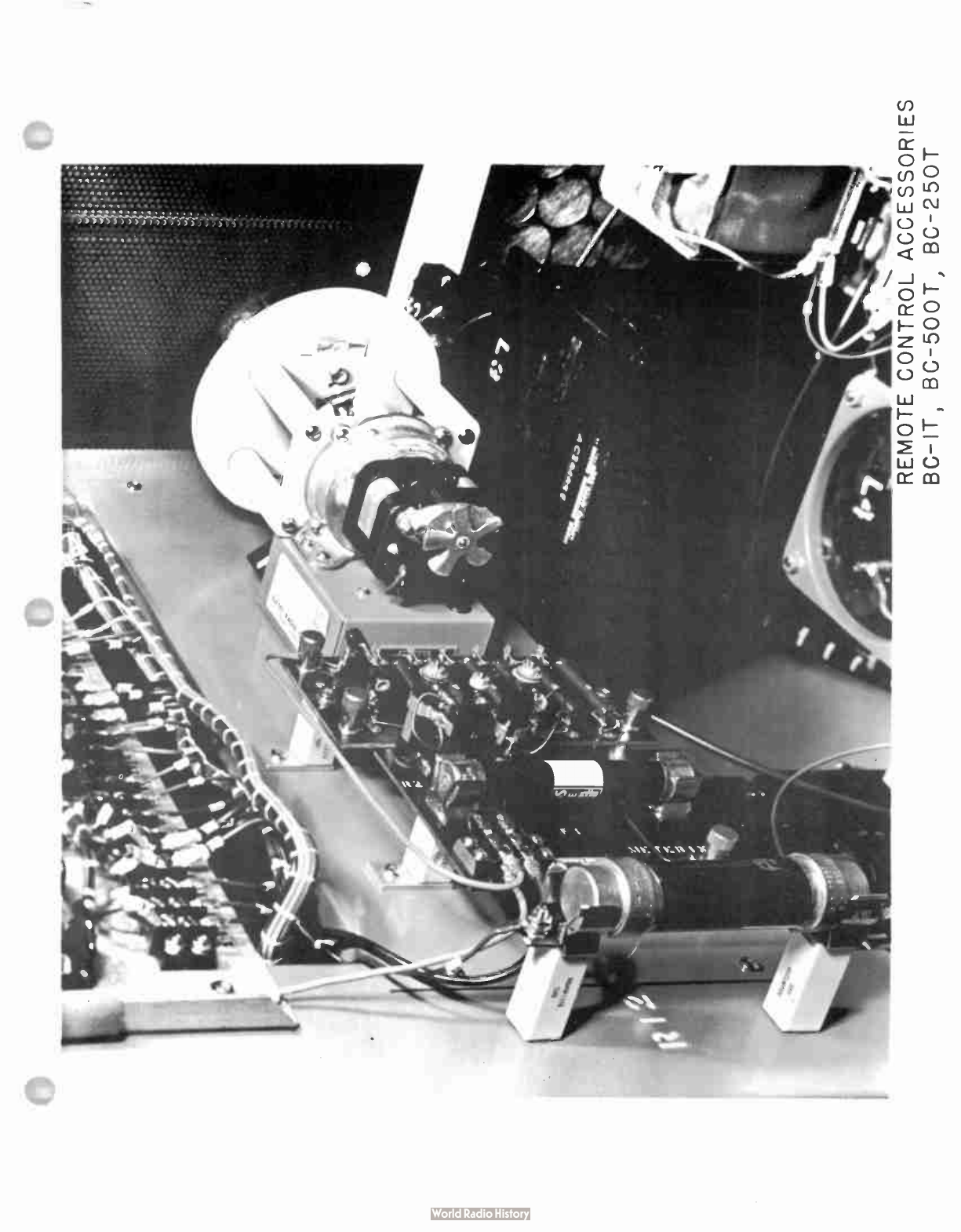
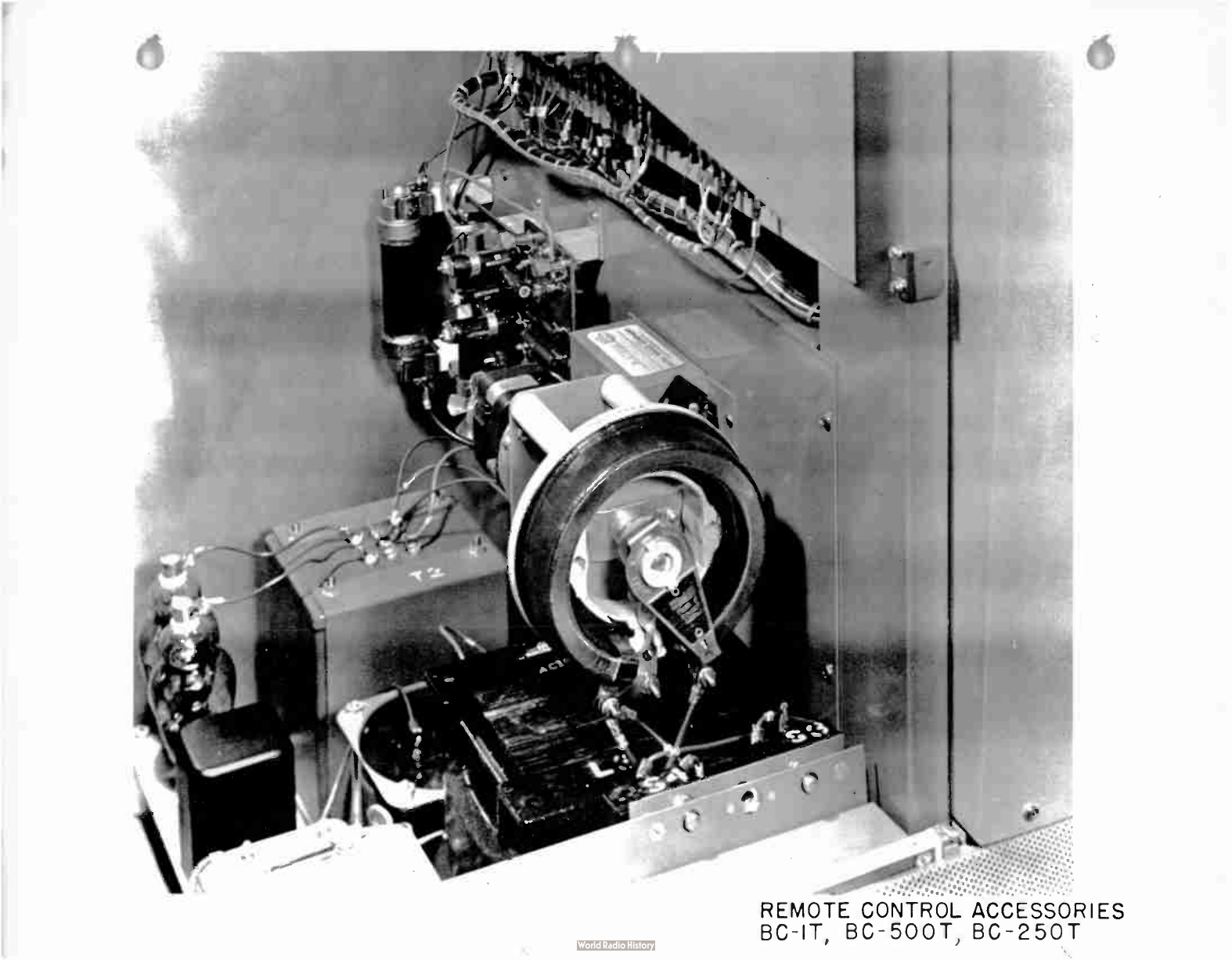
REMOTE
CONTROL
ACCESSORIES
BC-
IT,
BC-
500T,
BC-
250T

ADDENDA
SdEET
INSTALLATION
INSTRUCTIONS
FOR
R102E
CONTROL
IN
GATES
TRjINSMITTERS
BC-
1T,
BC-
500T,
BC-
250T
Refer
to
the
following
overall
transmitter
schematic
diagrams:
BC- 1T -
C-78130
BC-
500T -
E-25569
BC-
250T -
E-25582
A
steel
plate,
drilled
for
mounting
the
M-4719
Plate
Voltage
Kit,
M-4720
Plate
Current
Kit
and
M-4703
Rheostat
Assembly,
is
available
for
the
installer's
use.
Tapped
mounting
holes
for
this
plate }
lave
been
provided
in
the
cabinet
corner
supports,
directly
beneath
the
terminal
boards
and
conactors (
right
side
of
transmitter
as
viewed
from
front).
Photographs
showing
the
remote
control
kits
in
place
is
included
witn
these
instructions.
M-4703
Motor Rheostat
Assembly
As
viewed
from
the
rheostat
end
of
this
assembly,
with
the
three
rheostat
terminals
to
the
left,
strap the
center
terminal (
arm)
to
the
top terminal.
Since
application
of "
increase"
voltage
brings
about
clockwise
rotation
of
the
arm (
same view),
resistance will
decrease. ,
riti
application
of .
idecrease°
voltage,
the
resistance
will
increase.
2he
existing
plate
voltage
meters
in
the BC-
1T,
BC-
500T
and
BC-
250T
Transmitters
read
plate
to
cathode
voltage,
whereas
the
remote con-
trol
voltage
sampling
kit
will
read
plate
to
ground
voltage.
There-
fore,
in
order
for
the
two
meters
to
track
the
rheostat
must
be
wired
in
series
with
the
high
voltage
lead
feeding
the
final
amplifier.
Proceed
as
follows:
1.
Disconnect
from
modulation
reactor
L-3,
the
high
voltage
lead
which
runs
upward
to
the
final
amplifier
RF
choke
L-9.
Remove
this
wire
from
the
cable
until
sufficient
length
is
available,
thet
connect
to
one of the
motor
rheostat
terminals.
2.
Using
Packard
cable
or
a
high
voltage
equivalent,
run
a
lead
from
the
other
rheostat
terminal
to
this
same
modula-
tion
reactor
terminal
discussed
in
Step
1.
Set
the
trans-
mitter
voltage
control
R-14,
for
maximum
voltage (
minimum
resistance).
3.
The
control
circuit
hook-up between
the
M-4703
motor
and
remote .
s,ontrol
unit
is
explained
in
the
Re:lote
Control
instruction
book.
-1-

Plate
Voltage
Extension
Kit
M-4719
1.
Using
Packard
cable
or
a
high
voltage
equivalent,
connect
the
M-4719
1
1-1V' terminal
to
the
motor
rheostat
terminal
furthermost
from
the
poWer
supply.
Do
not
connect
to
the
rheostat
terminal
which
goes
to
the
modulation
reactor.
Connect
the
M-4719
kit
termiA.al -
G. to
a
good
ground
point
within
the
transJylitter.
2.
Refer
to
the
Remote
Control
Instruction
Book
for
connection
of
meter
sar.cple
voltage
to
remote
control
unit.
Plate
Current
Extension
Kit
M-4720
1.
The
plate
current
kit
is
to
be
connected between
the
lower
end
of
the
P.A.
overload
relay
K-6
and
ground.
2.
A
ground
lead
runs
from
a
chassis
ground
terminal
to
one
of
the
coil
terminals
on
K-7
modulator
overload
relay,
then
to
one
coil
terminal
of
K-6
P.A.
overload
relay.
Clip
out
the
portion
between
K-6
and
K-7.
K-7 is
to
retain
its
direct
chassis
ground
since
we
want
only
P.A.
current
to
flow
through
the
plate
current
kit.
3.
Both
K-6
and
K-7
must
retain
their
shunt
resistors
directly
across
their
respective
coils.
4.
The "
G
terminal
of
the
two-
terminal
strip
on kit
M-4720
connects
to
a
good
ground
point
within
the
transmitter.
Run
a
lead
from
the
other
terminal,
upward
to
the
K-6
te_aainal
which
was
formerly
grounded.
5.
Refer
to
the
Remote
Control
Instruction
Book
for
connection
of
sampling
voltage
to
Remote
Control
Unit.
Remote
Plate
Start-
too
Circuitry
The
BC-
1T,
BC-
500T
and
BC-
250T
overall
schematic
diagrams
plainly
in-
dicate
the
necessary
connections
for
filament
and
plate
remote
control.
The
plate
start-
stop
circuitry
consists
merely
of
shunting
the
trans-
mitter
plate-
start
switch
with
a
set
of
n)rmally
open
remote
control
contacts.
The )
late-
stop
function
is
accomplished
by
connecting
a
set
of
normally
closed
remote
contacts
in
series
with
the
transmitter
plate-
stop
switch.
Remote
Filament
Start-
Stop
Circuitry
Note
that
a
jumper
is
to
be
removed
in
the
filament
contactor
circuit.
Removal
of
this
jumper
disables
the
holding
contacts
on
the
filament
contactor.
A
set
of
remote
normally
-
opon
contacts
shunted
across
the
transmitter's
filament-
start
switch
will
then
serve
as
filament
start
-2-

and
hold,
satisfying
FCC
requirements
for
a '
fail-safe'
circuit.
If
the
telephone
line
between
studio
and
transmitter
fails,
or if
the
remote
control
equipment
becomes
defective
the
remote
holding
con-
tacts
open.
Tnis,
in turn,
causes
the
filament
contactor
to
drop
out,
removing
the
transmitter
from
the
air.
In
multiple
transmitter
installations,
the
filament-
fail
safe
opera-
tion
is
accomplished
in
a
slightly
different
manner,
so
that
indivi-
dual
filament
control
for
the
various
transmitters
is
possible.
Each
transmitter
employs
its
individual
slave
relay
associated
with
its
respective
transmitter
filament
contactor.
The
fail-safe
relay
in
the
remote
control
unit,
in
turn,
holds
energized
all
of
the
slave
relays.
The
slave
relay
contacts
are
wired
in
series
with
their
respective
filament
cont,actor
off
circuits,
providing
a
holding
circuit.
Thus,
separate
on-
off
filament
control
is
possible
for
each
transmitter.
These
circuits,
along
with
drawings,
are
preseni;ed
in
detail
in
the
Remote
Control
Instruction
Book.

INDEX
Page
Section
I
Electrical
Description
1
Section
II
Mechanical
Description •
1
Section
III
Installation
2
Section
IV
Gates
BC-
250T
Transmitter
Details
3-11
Section
V
Initial
Tune-up
of
Gates
BC-
250T
12-16
Section
VI
General
Operating
Procedure
17-18
Section
VII
Summary
19
Guarantee
1-2
Photographs
Electrical
Parts
List
1-5
Drawings
A-30957 -
Tuning
Chart,
BC-
250T
A-30958 -
Typical
Voltage
Chart
A-30584 -
Typical
Curves,
Vacuum
Ovenless
Crystals
A-30585 -
aood Base
B-13816 -
Schematic,
M-5422
Oscillator
Unit
B-65286 -
Schematic,
Driver
Unit
C-77711 -
Schematic,
Audio
Input/C.thode
Follower
C-77723 -
Simplified
Schematic,
Control
System
C-77736 -
Outline
Diagram
B-65293 -
Bias
Supply,
BC-
250T
E-25582 -
Main
Overall
Schematic
1/16/58
-1-
BC-
250T
Xmtr.
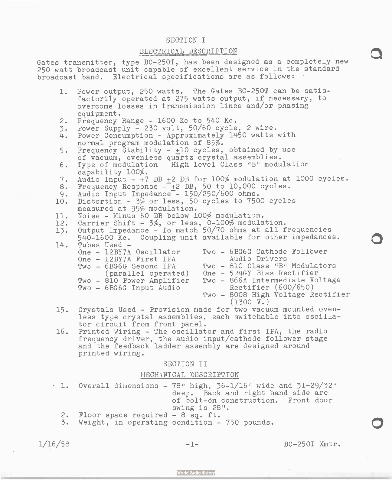
SECTION
I
ELECTRICAL
DESCRIPTION
Gates
transmitter,
type
BC-
250T,
has
been
designed
as
a
completely new
250
watt
broadcast
unit
capable
of
excellent
service
in
the
standard
broadcast
band.
Electrical
specifications
are
as
follows:
1.
Power
output,
250
watts.
The
Gates
BC-
250T
can
be
satis-
factorily
operated
at
275
watts
output,
if
necessary,
to
overcome
losses
in
transmission
lines
and/or
phasing
equipment.
2.
Frequency
Range -
1600
Kc
to
540
Kc,
3.
Power
Supply -
230 volt,
50/60
cycle,
2
wire.
4.
Power
Consumption -
Approximately
1450
watts
with
normal
program
modulation
of
85%.
5.
Frequency
Stability - +
10
cycles,
obtained
by
use
of
vacuum,
ovenless
quartz
crystal
assemblies.
6.
Type
of
modulation -
High
level
Class
modulation
capability
100%.
7.
Audio
Input - +
7
DB +
2
DB for
100%
modulation
at
1000
cycles
8.
Frequency
Response -
-+2
DB,
50 to
10,000
cycles.
9.
Audio
Input
Impedance
--
150/250/600
ohms.
10.
Distortion -
3% or
less,
50
cycles
to
7500
cycles
measured
at
95%
modulation.
11.
Noise -
Minus
60
DB
below
100%
modulatian.
12.
Carrier
Shift -
3%,
or
less,
0-100%
modulation.
13.
Output
Impedance -
To
match
50/70
ohms
at
all
frequencies
540-1600
Kc.
Coupling
unit
available
for
other
impedances.
14.
Tubes
Used -
One -
12BY7A
Oscillator
Two -
6BG6G
Cathode
Follower
One -
12BY7A
First
IPA
Audio
Drivers
Two - 6BG6G
Second
IPA
Two -
810
Class
uB.'
Modulators
(parallel
operated)
One -
5R4GY
Bias
Rectifier
Two -
810
Power
Amplifier
Two -
866A
Intermediate
Voltage
Two -
6BG6G
Input
Audio
Rectifier (
600/650)
Two -
8008
High
Voltage
Rectifier
(1300
V.)
15.
Crystals
Used -
Provision
made
for
two
vacuum
mounted
oven-
less
type
crystal
assemblies,
each
switchable
into
oscilla-
tor
circuit
from
front
panel.
16.
Printed ‘
Firing -
The
oscillator
and
first
IPA,
the
radio
frequency
driver,
the
audio
input/cathode
follower
stage
and
the
feedback
ladder
assembly
are
designed
around
printed
wiring.
SECTION
II
HEC
-
di.IÏICAL
DESCRIPTION
1.
Overall
dimensions -
78"
high,
36-1/16
wide
and
31-29/32"
deep.
Back
and
right
hand
side
are
of
bolt-
On
construction.
Front
door
swing
is
28.
2.
Floor
space
required -
8
sq.
ft.
3.
Weight,
in
operating
condition -
750
pounds.
1/16/58
-1-
BC-
250T
Xmtr.
C
C
SECTION
III
INSTALLATION
This
instruction
book
affords
valuable
information
for
persons
who
are
installing
and
operating
the
Gates
BC-
250T
transmitter.
The
following
mentioned
points
should
be
studied
so
that
the
unpacking
and
setting
up
procedure
will
be
well
in
mind
when
doing
the
actual
work.
1.
Check
all
packing
lists
for
materials
supplied.
2.
Study
the
instruction
book
before
attempting
to
set
up
the
equipment.
3.
Have
the
transmitter
location
clean
so
that
the
various
parts
can
be
safely
placed
out
of
harms
way
when
the
unit
is
unpacked.
4.
It
is
well
ta
have
a
mounting
base,
set
in
place,
upon
which
the
transmitter
can
be
set.
This base
can
be
made
from
2°
x
4°
lumber
dimensioned
as
shown
in
Gates
Dwg.
A-30585.
It
should
be
painted,
preferably
black.
This base
should
be
lagged
to
the
floor
and
measures
taken
to
insure that
the
top
side
of
the
frame
is
perfectly
level.
This
will
give
a
good,
solid,
level
base
on
which
the
transmitter
can
be
set.
This
procedure
also
allows
the
external
transmitter
wiring
to
enter
the
cabinet
from
practically
any
point
underneath
and
be
run
to
the
entry
holes
provided
in
the
base
of
the
cabinet.
5.
Use
heavy primary
wire
from
the
building
switch
box
terminals
to
the
transmitter
fuse
block.
or
M3
copper
wire
should
be
suitable
for
these
two
leads.
6.
Be
sure
the
power
company
has
installed
large
enough
service
for
all
the
equipment,
transmitter,
lights,
water
pump,
etc.,
which
will
be
used
at
the
transmitter
site.
7.
Do
a
good
job
of
installing
the
equipment.
Time
spent
in
making
the
installation
as
good
electric-
ally
and
mechanically
as
possible,
will
pay off
in
the
future
by
insuring
less,
off- the-
air
time.
1/16/58
-2-
BC-
250T
Xmtr.
SECTION
IV
BC-
250T
TRANJMITTER
DETAILS
The
transmitter
has
been
readied
for
shipment
by
having
all
tubes
removed
from
their
respective
sockets,
relay
contacts
have
been
blocked
and
tied
and
other
parts,
such
as
parasitic
suppressors,
tube caps
and
leads,
etc.,
tied
down
securely
to
prevent
damage
during
shipment.
Vacuum
enclosed
time
delay
relays
have
been
re-
moved
from
their
sockets.
The
power
amplifier
RP
choke,
L9,
and
the
coupling
capacitor,
C9,
also
have
been
removed.
The
connector
straps
have
been
adequately
tagged
for
easy,
correct
re-
connection.
These
components
have
been
adequately
marked
and
packed
in
cartons
that
are
in
turn
safely
secured
within
the
transmitter.
All
of
the
power
and
modulating
equipment
has
been
shipped
intact
within
the
cabinet,
thus
relieving
tile
installation
engineer
of
the
re-
instal-
lation
of
these
components.
Coil
L13
located
at
top
rear
of
cabinet
has
special
mounting
straps
provided
to
insure
safe
travel during
transit.
These,
along
with
all
other
packing
material,
string,
tape,
etc.,
should
be
removed
from
the
components.
All
relays should
be
inspected
for
free
travel
of
armatures
and
con-
tacts.
The
following
information
concerning
the
Gates
BC-
250T,
per-
tains
to
its
general
construction
and
operation.
It
is
highly
de-
sirable
to
study
the
various
sections
of
the
transmitter
in
order
to
completely
understand
and
comprehend
its
operation.
The
complete
transmitter
is
built in
a
welded
steel
cabinet
with
most
of
the
low
power
RF
and
audio
components
mounted
vertically
on
a
formed
aluminum
panel
and
shelf
assembly.
The
high
power
modu-
lators
and
power
amplifier
810's
are
located
on
a
tube
shelf
at
the
top
of
this
basic
assembly.
The
power
amplifier
tuning
and
loading
components
are
mounted
on
a
large
aluminum
panel
assembly
at
the
top
of
the
cabinet.
This
assembly
is
perforated
to
allow
the
heated
air
within
the
cabinet
to
pass
through
it
and
then
out
of
cabinet.
Located
in
the
base
of the
transmitter
are the
heavy
power
components,
such
as
power
transformer,
rectifier
filament
transformers,
filter
-omponents,
modulation
choke
and
transformer,
and
rectifier
tubes.
The
transmitter
is
completely
dead
front;
there
is
a
perforated
metal
inner
shield
extending
downward
from
the
power
amplifier
panel
to
the
air
intake
panel.
The
inner
shield
is
joined
to
the
air
filter
panel
by
means
of
two
thumb "
quick
off"
fasteners.
1,
fear
the
right
hand
fastener
are
the
interlocks
for
the
600
volt
and
1350
volt
power
sup-
plies.
All
controls
are
available
to
the
operator
through
a
cut
out
in
this
perforated
screen
panel.
If
this
panel
is
removed,
the
600
volt
and
1350
volt
power
supply
interlocks
function,
removing
these
voltages
from
the
transmitter.
This
transmitter
is
crystal
controlled
by
means
of
the
il
-
5422
oscil-
lator
unit
which
is
located
on the
panel
and
shelf
assembly.
The
crystal
change-
over
switcn,
Sl,
along
with
the
frequency
adjust
vari-
able
condensers,
Cl
and
C2,
are
cinveniently
located
on
the
front
control
panel.
The
M-5422
frequency
control
unit
uses
a
12BY7A
tube
1/1
6/58
-3-
BC-
250T
Xmtr.
connected
circuitwise
as
an
electron
coupled
oscillator,
controlled
by
a
vacuum
mounted,
ovenless
type
crystal
assembly.
Positions
for
two
crystals
is
provided
in
the
oscillator
unit.
The
untuned
plate
circuit
of
the
oscillator
is
capacity
coupled
to
the
grid
of
the
first
IiA,
another
12BY7A
physically
located
in the
small
oscillator
unit.
This
stage
operates
under
very
c)nservative
conditions
and
makes
a
fine
isolation
buffer
between
the
oscillator
and
the
R.2.
driver.
Due
to
the
conservative
operating
potentials
and
the
extremely
low
crystal
cUrrents,
the
M-5422
oscillator
unit
has
exceptional
frequen-
cy
stability.
The
crystals
are
of
a
low
teifeperature
co-
efficient
type
which
do
not
need
a
heated
oven
to
maintain
frequency
well
within
FCC
limits.
Frequency
trimmers,
Cl
and
02,
provide
a
small
deree
of
frequency
adjustment
which
may
be
required
if
the
crystals
age.
The
M-5422
oscillator
unit
is
easily
tuned
to
the
operating
frequency.
No
tuning
is
required
for
the
oscillator
itself,
just
insert
the
cry-
stal,
or
crystals,
and
set
the
crystal
selector
switch
accordingly.
The
first
IPA
stage (
12BY7A,
V2
in
unit)
must
be
tuned.
Provision
is
made
to
supply
U.F.
voltage
from
a
resistive
divider
at
the
output
of
the
M-5422
oscillator
to
a
frequency
monitor
such
as
the
Gates
M-2890.
This
monitor
drive
is
available
between
terminal #
27
on
TB1
and
ground.
See
overall
schematic
-
J'e-25582.
For
typical
voltages
occurring
in
the
oscillator
unit
see
Gates
Dwg.
A-30958.
The
total
plate
current
drawn
by
the
oscillator
and
first
nA
tubes
in
the
osc-
illator
unit
is
in
the •
neighborhood
of
20
to
25
ma.
as
measured
on
the
multimeter
when
the
multimeter
switch
is
in
the
position
marked
'Plt.
Our.
Osc/Bufl.
The
positive
plate
potential
applied
to
the
oscillator
unit
is
derived
from
the
600 volt
power
supply
through
a
20,000
ohm
dropping
resistor,
R9.
Printed
wiring
is
used
in
this
oscillator
unit.
The
second
IPA
stage
ases
two
6BG6G
beam
power
pentodes
operating
in
parallel.
These
tubes
nave
approximately
600/650
volts
applied
to
their
plates.
The
cathode
current
of
the
two
6BG6G
tubes
will
run
between
150
and
200
ma.
depending
upon
loading
and
operating
fre-
quency.
This
cathode
carrent
is
indicated
on
the
multimeter
when
the
selector
switch
is
set
to
'
RF
Driver
Cath..
The
stage
is
tuned
from
the
front
panel
by
control
knob
designated
at
Ji3.2
Driver
Tuning'.
This
stage
will
tune
from
1600
Kc
to
1050
ic
with
no
padding
conden-
ser
required.
Jee
frequency
determining
component
chart,
Gates
Dwg.
A-30957.
Thee
is
meter
indication
of
the
112
drive
supplied
to
the
two
6BG6G's
by
setting
the
selector
switch
to
position
marked
.
1i1J'
Driver
Grid'.
In
normal
operation
the
grid
current
indication
of
this
stage
will
be
on
the
order
of
.3
to .
5
ma.
lith
normal
voltages
applied
and
adequate
grid
drive
the
6BG6G's
in
this
RF
driver
stage
will
supply
between
100
and
120
grid
mils
to
the
power
amplifier.
This
current
will
vary
according
to
tuning
and
operating
frequency,
but
should
never
run
less
than
100
ma.
This
F.A.
grid
current
is
also
measured
by the
multimeter,
being
indicated
on
the
meter
when
the
selector
switch
is
placed
in
the "
Power
Amp.
Grid"
position.
The
plate
dissipation
of
the
two
6BG6G tubes
is
kept
within
accept-
able
limits
by the
use
of
a
cathode
resistor,
1i2,
used
for
develop-
ing
some
cathode
bias.
If
the
drive
to
this stage
is
lost,
the
cath-
ode
developed
bias
will
tend
to
hold
the
plate
current
within
reason-
able bounds. Most
of
the
circuitry
of
this
2nd
IPA
stage
is
made
1/16/58
-4- BC-
250T
Xtr.
up
of
printed
wiring,
only
the
plate
coil,
L8,
tuning
capacitors,
07
and
015,
and
plate
choke,
L7,
are
mounted
external
to
the
printed
wiring
board.
The
plate
voltage
which
energizes
the
two
6BG6G
RF
drivers
is
develop-
ed
in
a
600/650
volt
power
supply
using
two
866A
tubes
as
rectifiers.
Typical
voltages
appearing
within
this stage
are
shown
on Gates
Dwg.
A-30958
and
also
on
Schematic
B-65286.
Neutralization
of
the
power
amplifier
is
accomplished
by
the
"
Ricen
method,
the
out
of
phase
voltage
being
obtained
from
the
6BG6G
tank
coil,
L8.
There
are
several
taps
brought
out
adjacent
to
the
elec-
trical
center
of
this
coil,
these
taps
affording
rough
neutraliza-
tion.
By
means
of
the
variable
neutralizing
condenser,
010
and
these
taps,
it
is
possible
to
completely
neutralize
the
810
tubes
in the
power
amplifier.
The
neutralizing
condenser,
C10,
can
be
adjusted
from
the
front
of
the
transmitter,
by
use
of
a
screw
driver
working
through
the
small
aperture
in
the
lower
right
side
of
the
upper
front
panel.
The
neutralizing
condenser,
010, is
located
directly
behind
this
front
panel,
its
shaft
being
insulated
by
means
of
a
slotted
bakelite
shaft
bushing.
The
power
amplifier
makes
use
of
two
810
tubes.
Most
of
the
power
amplifi'úr
and
output
circuitry
is
mounted
on
an
aluminum
panel
and
chassis,
assembly
at
the
top
of
the
cabinet.
The
heated
air
4)asses
through
the
P.A.
assembly
through
numerous
openings.
This
P.A.
assembly
is
,.
lade
up
of
PA
tank
coil,
L12,
PA
tank
condensers,
Cil
and
012, (
always
operating
in
parallel)
outpuL,
coils, L13
and
L14,
loading
condensers,
C13
and
C14,
modulation
pick-
up
coil,
L15,
plate
blocking
condenser,
C9,
and
plate
bypass
conden-
ser,
C8.
The
amplifier
circuit
consists
of
an °
L.'
and
two .'
f°
sec-
tions,
a
circuit
proved
over
the
years
as
one
which
is
flexible
and
also
very
effective
in
attenuation
of
undesirable
harmonics.
The
coil
and
capacitor
values
as
supplied
with
the
transmitter,
are
ef-
fective
in
loading
into
a
51.5
ohm
load. 3ee
tuning
chart,
Dwg.
A-30958.
The output
circuit
of
the
BC-
250T
includes
a
pickup
coil,
L15,
which
supplies
sufficient
RF
voltage
to
operate
a
modulation
monitor
such
as the
Gates
MO-
3629.
This
voltage
is
available
at
a
small
terminal
board,
TB2,
located
on
the
front
panel,
at
the
left,
ins'
This
amplifier
makes
use
of
no
variable, air
dielectric
condensers
(except
the
neutralizing
condenser,
010).
The
P.A.
tank
circuit
is
tuned
by
means
cf
a
rolling
contact
induc-
tor,
L12.
This
method
of
tuning
is
helpful
in
preventing
arcs
or
flash-overs
that
may
occur
in
variable
air
dielectric
condensers,
especially
if
the
transmitter
is
used
in
locations
where
the
dust
problem
is
bad.
The
P.A.
tank
condensers
are
two
type
G1
Sangamo
mica's,
always
connected
in
parallel.
The
combined
total
value
will
range
from .
0004
mfd.
at
1600
Kc
to .
001
mfd.
at
540
Kc.
The
load-
ing
condensers,
013
and
014,
also
vary
according
to
frequency.
For
information
concerning
these
variable
frequency
determining
compen-r
4-
see
Gates
Dwg.
A-30957 included
in
this
instruction
book.
1/1
6/59
-5-
BC-
250T
Xmtr.
The
power
amplifier
plate
current
is
read
on
M2,
a
0-500
MA
DC
meter.
This
current
will
generally
run
from
260
ma.
to
280
ma.
depending
upon
the
efficiency
and
the
applied
plate
voltage.
The
normal
plate
voltage,
as
read
on
plate
voltmeter,
113,
will
be
around
1350
volts,
As
mentioned
previously,
the
P.A.
grid
current,
as
indicated
on
the
multimeter,
will
be
100 to 120
ma.
depending
upon
frequency,
tuning,
etc.
Two
F.A.
tuning
control
knobs
are
located
on
the
power
ampli-
fier
panel,
the
left
hand
one
controls
the
variable
output
coil,
L14,
and
is
marked '
Loading.
The
right
hand knob
allows
rotation
of
the
variable
P.A.
tank
coil
tuning
the
power
aMplifier.
This
control
is
marked '
P.A.
Tune.
The
power
amplifier
is
protected
from severe over-
load
by
a
cathode
overload
relay.
This
relay,
K6,
is
located
on
the
aluminum
shelf
adjacent
to
the
multiple
810
filament
transformer,
T9.
Its
coil
is
shunted
by
a
semi-
variable
resistor,
R21,
this
resistor
allows
the
trip
out
point
to be
varied
considerably
above
and
below
the
normal
cathode current
drawn
by
the
810
power
amplifier
under
normal
conditions.
This
relay
shunt
resistor
is
adjusted
to
allow
the
relay,
K6,
to
pull
in
at
about
325
ma.
As
normal
cathode
current
will
be
around
260
to
280
ma.
this
gives
considerable
operational
latitude
before
the
transmitter
will
kick
off the
air.
Of
course,
this
adjustment
can
be
made
to
suit
the
individual
who
operates
the
equi:)ment.
Ihen
F.A.
overload
relay,
JÇ:6,
pulls
in,
its
contacts
close,
completing
a
230
volt
AC
circuit
through
the
coil
of
master
overload
relay,
K3.
K3
energizes
and
its
contacts
open,
causing
the
holding
circuit
of
the
plate
contactor,
K2,
to
open
and
drop
out
the
plate
relay.
This
de-
energizes
the
main
power
transformer,
Tl.
Audio
wise,
the
Gates
BC-
250I
transmitter
is
novel
in
many
respects.
The
audio
input
and
audio
driver
portion
is
made
up
of
printed
wir-
ing.
A
small
bakelite
printed
board
located
on
the
panel and
shelf
assembly
mounts
the
two
6BG6G audio
input
tubes,
the
two
6BG6G
cath-
ode
follower
tubes,
along
with
balance
control,
condensers
and
resistors
for
these
two
stages.
The
audio
input
connections
are
made
to
TB1-29
and
TB1-30,
with
a
convenient
ground
termination
on
TB1-28.
Provisions
have
been
made
on
audio
input
transformer,
T6,
to
allow
the
input
impedance
to
be
either
125,
250 or
600
ohms.
The
input
transformer
is
connected
for
600
ohm
operation
when
the
transmitter
leaves
the
factory.
This
will
take
care
of
most
audio
iruut
requirements.
A
balance
control,
.
13,
is
located
on
the
printed
circuit
board
near
the
right
hand
lower
cor-
ner.
This
control
is
in
the
cathode
circuit
of
the two
6BG6G
audio
input
tubes,
V1
and
V2.
By
use
of
this
control,
low
frequency
audio
distortion
can
be
mini-
mizes.
This
is
best
accomplished,
when
test
equipment
is
available
to
show
the
actual
distortion
present.
If
no
such
equipment
is
handy,
it
would
be
reasonable
to
adjust
this
balance
control
to
mid-
value
and
so
operate
the
transmitter.
The
second
audio
stage,
a
pair
of
6BG6G
tubes,
V3
and
V4,
aro
operated
as
cathode
followers,
these
tubes
provide
a
low
impedance
driving
source
for
the
grids
of
the
two 810
modulators.
1/16/58
-6-
BC-
250T
Xmtr.

Plate
potential
for
the
audio
input
and
cathode
followers
is
provi-
ded by
the
600/650
volt
power
supply,
mentioned
previously
as
sup-
plying
voltage
to
the
M-5422
oscillator
unit
and
the
RF
driver
stage.
Normal
voltages
to
be
expected
at
various
points
in
the
audio
input
circuits
are
given
in Gates
Dwg.
A-30958
9
typical
voltages.
The
cathode
current
of
the
two
audio
input
tubes,
V1
and
V2,
is
measured
by
multi-
meter,
the
selector
switch
being
set
at "
Input
Audio
Cathode.
This
current
will
normally
run
from
5
to
10
ma.
The
cathode
follower
tubes,
V3
and
V4,
are
biased
by
voltage
con-
trolled
by
potentiometers,
112
and
R1,
located
on
the
small
aluminum
front
panel.
These
controls
indirectly
adjust
the
operating
bias
on
the
modulators
by
varying
the
operating
constants
of the
cathode
fol-
lowers,
this
causes
a
bias
voltage
change
on the
modulators
by
having
a
voltage
drop
occur
across
the
high
resistance
cathode
resistors,
Rll
and
1112,
of
the
cathode
followers.
A
very
smooth
modulator
bias
change
can
be
attained
in
this manner,
making
it
possible
to
adjust
the
modulators
for
correct
operating
conditions.
There
is
no
meter
plate
current
indication
for
the
cathode
follower
tubes,
V3
and
V4,
it is
believed
that
if
proper
modulator
operation
is
had,
then
the
6BG6G
cathode
followers
are
operating
satisfactorily.
All
external
connections
to
the
audio
printed
wiring
is
made
to
numbered
terminals, this
is
shown
clearly
on
small
individual
draw-
ing
C-77711
of
this
section,
and
in
the
overall
schematic
E-25582.
High
level
Class "
JP
modulation
is
used
in
the BC-
250T,
a
pair
of
810
tubes
providing
the
means.
The
modulation
transformer, £
3,
working
with
these tubes
is
located
in
the
base
of
the
cabinet,
on
the
right
hand
side,
toward
the
rear.
The
grids
of
the
modulators
are
excited
by
the
two
6BG6G
cathode
followers.
The
modulators
operate
with
approximately
30
na,
static
plate
current
per
tube,
this
operating
parameter
being
set
up
from
the
front
panel
by
use
of
the
two ' bias"
controls,
R1
and
112.
To
enable
the
operator
to
individually
adjust
each
modulator
tube,
a
meter
switching
circuit
has
been
designed.
A
three
position
switch,
31,
is
located
on
the
aluminum
front
panel,
just
below
the two
bias
controls.
This
switch
has
markings
as
follows;
in
the
left
position
Modulator
1,
1, (
V8)
is
metered,
in
the
right
hand
positi.rn
Modulator /,
4
2 (
V9) is
metered
and
when
the
switch
is
in
the
center
position
marked "
Total,
both
tube
currents
are
combined
and
read.
These
currents
are
indicated
on
the
modulator
front
panel
meter,
114.
The
total
plate
current
will
be
from
250
to
300
ma.
during
times
of
heavy
modulation.
Each
modulator
has
its
filament
energized
by
a
separate filament
winding
on
multiple
filament
transformer,
T9.
The
third
winding
on
this
transformer, £
9,
is
10V,
9
ampere
capacity
and
energizes
the
filament
of
the
power
amplifier
tubes,
V6
and
V7.
The
modulators
are
protected
from
severe
overload
by
relay,
K7.
This
relay,
K7,
is
also
provided
with
a
coil
shunt
resistor,
1122,
making
it
possible
to
adjust
the
pull-
in
point
of
the
relay.
For
normal program
modulation
the
modulator
plate
current
should
not
exceed
perhaps
300
ma.
Under
sine
wave
audio
conditions
this cur-
rent
may
rise
to
400
ma.
at
the
higher audio
frequencies.
A
1/16/58
-7-
BC-
250T
Xmtr.

satisfactory
setting
for the
overload relay
would
be
around
450
ma.
This
will
take
care
of
accidental
audio
peaks
that
might
go
through.
This
overload
relay,
K7,
has
its
normally
open
contacts
connected
in parallel
with
the
normally
open contacts
of P.A.
overload
relay,
K6.
If
a
modulator
overload
does
occur,
the
K7
modulator
overload
relay
pulls
in
causing
230
volts
a.c.
to
be
applied
to
the
coil
of
master
overload
relay,
K3,
which
in
turn
energizes
and
pulls
in
to
open
the
holding
circuit
of
plate contactor,
K2.
This
removes
the
high
voltage
from
the
modulators
and
the
power
amplifier.
Feedback
from
the
plates
of
the
modulators
back
to
the
audio
input
tube
grids
has
been
provided.
A
small
bakelite
priated
wiring
board
is
located
on
the
panel
and
shelf
assembly,
directly
above
the
modulation
transformer,
T3.
By
means
of
a
resistor/capacitor
divider
network
out
of
phase
voltage
is
fed
bac!:
to
the
audio
in-
put.
The BC-
250T
transmitter
makes
use
of
approximately
9
DB
of
feedback
measured
at
1000
cycles and
90c/;
modulation.
This
feedback
helps
to
reduce
the
hum
and
also
improves
the
distortion
figures. •
All
relays
for
the
operation
of
the
transmitter
are
mounted
on
the
panel
and
shelf
a
ssembly,
the
previously
mentioned
P.A.
and
the
modulator
overload
relays,
K6
and
K7,
being
on
the
top
shelf
ad-
jacent
to
the
multiple
filament
transformer, .
29.
All
other
relays
are
mounted
at
the
bottom
of
the
panel
and
shelf
assembly
along
with
necessary
fuses,
time
delay
relays,
etc.
The
main
line
fuses,
Fl
and
F2,
are
located
at
the
left
bottom
section
of the
inside
panel
asseilbly,
directly
over
TB-
1.
This fuse
receptacle
is
the
terminal
location
for
the two
230
volt
primary
input
wires.
Fifteen
ampere
cartridge
fuses
are
used.
Next
in
line
is
the
filament
con-
tactor,
Kl.
Filament
contactor,
Kl,
is
energized
by
depressing
the
filament
start
switch,
S5,
located
on
the
front
column
directly
beneath
the
multimeter.
This
operation
causes
the
primary
input
voltage
to be
connected
directly
to
the
primaries
of
all
filament
transformer
(T4,
8008
fil.
trans.,
T5,
866A
fil.
trans.,
1
28,
dual
6.3
volt
fil.
trans.
for
audio,
RF
driver
and
osc.
unit
and
T9,
the
10
volt
mul-
tiple
fil.
trans.
for
the
modulators
and
power
amdlifier).
At
the
same
time
the
heater
for
time
delay
relay,
K5,
is
energized.
After
30
seconds
the
contacts
of
K5 (
low
voltage
time
delay)
close
and
this
action
energizes
the
primary
of
T2,
the
600/650
volt
power
transformer. (
If
the
interlock
switch,
33,
is
depressed.)
Along
with
tlis
sequence
of
events,
the
primary
of
the
bias
transformer,
T7,
is
energized
and
as
the
bias
rectifier,
V5,
heats,
bias
voltage
is
developed.
This
will
be
approximately
neg.
280
volts.
Listing
the
functions
performed
when
35,
the
filament
start
button, has
been
depressed,
we
have --
1.
All filaments
energized,
filament
pilot
light
on,
low
volt-
age
time
delay relay
heating.
2.
Bias
supply
energized,
neg.
280
volts,
developed
setting
up
bias
for
cathode
follower
and
modulators.
3.
600/650
power
supply
energized (
if
low
voltage
door
inter-
lock
S3
is
depressed).
This
has
energized
the
plate
circuits
of
the
crystal
oscillator,
first IPA
and
hF
driver and
if
they
are
correctly
tuned,
there
will
be
grid
drive
to
the
1/16/58
-8-
BC-
250T
Xmtr.

'power
amplifier.
Also
the
600/650
volts
has
been
applied
to
the
input
audio
and
cathode
follower
stage.
4.
High
voltage
time
delay
relay,
K4,
heated
and
its
control
contacts
closed. (
After
primary
of 12
is
energized.)
Plate
contactor,
K2,
is
located
next
to
the
filament
contactor,
near
the
lower
part
of
the
panel
and
shelf
assembly.
If
the
high
voltage
door
interlock
switch,
34,
is
closed
and
high
voltage
time
delay
re-
lay,
K4,
is
heated
and
its
contacts
closed,
it
would
be
possible
to
energize
this
plate
contactor,
K2,
by
depressing
the
plate
start
but-
ton
located
just
beneath
the
meter
column.
When
plate
contactor,
K2,
closes,
several
operations
occur.
1.
The
high
voltage
plate
transformer,
11
primary,
is
energized,
developing
high
voltage (
1350/1400
approx.)
for
and
modulator
plates.
2.
Plate
nilot light energizes.
This
would
place
the
transmitter
on
the
air.
The
Gates
BC-
250T
transmitter
makes
use
of
3
separate
power
supplies.
1.
Bias
Power
Supply.
It
is
made
up
of
a
combined
filament
and
plate
transformer
T7,
working
in
conjunction
with
bias
rectifier,
V5,
a
5R4GY,
filter
choke
L6,
filter
condenser
06
and
associated
resis-
tors
and
potentiometers.
The
bias
potentiometers,
R1
and
R2,
indirectly
vary
the
modulator
bias,
by
controlling
the
cathode
follower
bias
and
thus
the
current
flow,
through
the
cathode
follower
resistors,
Rh
l
and
R12.
There
is
ap-
plied
a
negative
280
volts
between
these
resistors
and
ground.
An opposing
voltage
of
approximately
240
volts
is
developed
by
current
flow
trough
Rll
and
R12,
thus
putting
the
difference (
about
30/40
volts)
on
the
grids
of
the
modulators.
This
supply
energizes
when
the
filament
start
button
is
depressed.
2.
600/650
Volt
Power
Supply
This
supply
makes
use
of
a
pair
of
866A
rectifiers,
the
filaments
of
which
are
heated
by
transformer,
T5.
The
primary
of
T5
is
energied
at
the time
the
fila-
ment
start
switch
is
operated.
Approximately
30
seconds
after
the
filaments
are
energized,
and
low
voltage
time
delay
relay,
K5,
has
heated
and
closed
its
contacts,
this
causing
the
primary
of
T2,
the
600/650
volt
power
transformer
to
energize (
if
the
low
voltage
door inter-
lock
switch
33
is
closed)
develop
approximately
600
volts
d.c.
after
being
rectified
by
V4
and
V3,
the
two
866A
rectifiers.
This
voltage
is
applied
to
the
M-5422
oscillator
unit
through
a
dropping
resistor,
E9,
which
reduces
it
to
approximately
195V.
The
600
volts
is
ap-
plied
to
the
RF
driver.
Also,
this
same
voltage
is
ap-
plied
to
the
audio
input/cathode
follower
stages.
The
1/16/58
-9-
BC-
250
.2
Xmtr.

primary
of
this
power
transformer (
T2)
is
fused
by
a
small
fuse,
F4,
of
3
ampere
size.
High voltage
for
the
modulators
and
power
amplifier
approximately
1350
volts
is
developed
by
a
power
supply
consisting
of
main
power
transformer,
Tl,
8008
filament
transformer,
T4,
swinging
choke,
Ll,
smoothing
choke,
L2,
and
filter
capacitor,
C2
and
C3.
These
components
are
located
in
the
base
of
the
transmitter
along
the
left
hand
side
and
to-
ward
the
front.
This
high
voltage
supply
is
inter-
locked
with
the
front
panel
grill
and
interlock
switch,
S4.
Provisions
have
been
made
to
operate
the
Gates
BC-
250T
transmitter
be
remote
control. The
connections
are
clearly
shown
on
Gates
over-
all
schematic
E-25582.
It
is
necessary
to
remove
the
jumper
wire
that
normally
connects
between
contact #
1
and #
3
on
a
filament
start
contactor,
Kl,
and
wire
normally
connected
between
TB1-10
and
TB1-22.
For
shipping
purposes,
some
components
have
either
been
removed
or
mechanically
made
secure
within
the
cabinet
proper.
All
of
the
re-
moved
items
are
boxed
and
th.e
carton
containing
them
is
shipped
with-
in
the
cabinet.
The
following
items
have
been
removed -
C
e
1.
All
Vacuum
Tubes.
2.
Time
Delay
Relays,
K4
and
K5.
Contacts
of
the
filament
and
start
relays have
been held
firm
by
use
of
paper
and
tape.
Tube
caps
and
parasitic
suppressors
have
been
taped
down
to
prevent
damage
by
vibration
during
shipment.
Certain
components
have been
supported
by
wooden
braces.
All
of
this
material
should
be
removed
from
the
transitter,
care
snould
be
taken
to
see
that
all
relays
are
free
of
foreign
material
that
wJuld
prevent
them
to
operate
normally.
The
connections
to
the
various components
that
have
been
removed
are
clearly
tagged
for
easy
and
correct
replace-
ment.
Remove
extra
coil
bracing
from
L13
which
is
located
in
the
top,
at
rear.
Check
all
mechanical
connections
for
tightness.
Replace
all
vacuum
tubes,
crystals
and
time
delay
ralays
in
their
correct
sockets,
check
locations
by
reference
to
overall
schematic
E-25582
and
the
various
pictures
that
are
supplied
as
a
part
of
this
instruction
book.
At
this
time
do
not
place
the
plate
caps
on
the
866A
rectifier,
V3,
and
V4,
and
the
808
rectifiers,
V1
and
V2.
The
external
connections
are
few and
these
are
easily
made
to
the
BC-
250T
transmitter.
The
230
volt,
50/60 cycle
AC
enters
the
cabi-
net
base
at
the
right
hand
side,
near
the
rear
corner.
The
two
primary
wires
connect
directly
to
the
fuse
block,
XF1.
The
shielded
audio
input
pair
enters
the
cabinet
at
the
right
hand
side
near
the
front.
These
connections
arc
made
to
the
terminals #
29
and #
30
on
TB1.
A
ground
is
close
by
on
terminal #
28.
1/16/58
-10-
BC-
250T
Xmtr.
The
modulation
monitor
connects
to
TB2-1 &
2.
This
terminal
board
is
located
on the
back
side
of
the
tuning
and
loading
panel,
at
the
left
front
side.
This
connection
can
be
made
with
shielded
twisted
pair,
such
as
is
used
in
audio
wiring.
The
frequency
monitor
connects
to
TB1-27
and
28,
the
ground
being
terminal #
28.
This
connection
can
be
made
of
shielded
single
con-
ductor
wire,
or
low
impedance
line
such
as
RG/62U.
A
ground
stud
is
provided
on
the
cabinet
frame
for
a
transmitter
ground
connection.
Located near
the
modulation
transformer,
T3,
this
connection
facilitates
the
grounding
of
the
transmitter
to
the
overall
station
ground
system.
A
copper
strap
can
be
brought
in
through
the
access
hole
in
the
right
rear
base
section
of
the
trans-
mitter. (
The
AC
primary
wires
were
brought
in
through
this
opening
also.)
This
internal
ground
follows
up the
cabinet
support
and
fin-
ally
connects
to
the
aluminum
PA
tuning
assembly
at
the
top
of
the
cabinet.
The
RF
output
termination
is
a
ceramic
feedthrough
insulator
located
close
to
the
output
coil,
L14.
Connection
can
be
either
made
from
the
top
of
the
cabinet
through
an
access
opening,
or
the low
impedance
line
can
be
brought
in
through
the
base
of
the
transmitter
and
con-
nected
to
the
out
-
put
circuit.
A
word
of
comment
here,
concerning
the
station
ground
system.
It
should
be
constructed
as
good
as
can
be,
all
connections
well
made
and
soldered,
or
preferably
brazed.
It
is
wise
to
bond
all
electri-
cal
conduit,
metal
frame
work
of
building,
water
piping,
etc.,
to
the
overall
ground
system.
If
these
suggestions
are followed,
there
will
be
less
trouble
over
the
years
as
the
ground
system
ages.
1/1
6/58
-11-
BC-
250T
Xmtr.
z
C.:
SECTION
V
INITIAL
TUNE-UP
OF
TIE
GATES
BC-
250T
Before
proceeding
with
the
initial
tune-up
of
this
transmitter,
it
would
be
well
to
re-
check
the
necessary
things
to be
done,
before
any
voltage
is
supplied.
Briefly,
check
the
following
list.
1.
Proper
primary
line
voltage
connected
to
fuse
bloCk,
XFl
e
two
15
ampere
fuses
should
be
in
the
clips
of
this
fuse
block.
2.
Proper locatipn
of
all tubes
in
sockets.
These
tube
locations
can
be
checked
by
reference
to
the
stencil-
ling
in
the
transmitter
and
to
information
furnished
in
this
instruction
book.
Also,
make
sure
the
crystal,
or
crystals,
are
in
the
oscillator
crystal
sockets.
If
only
one
crystal
is
used,
be
sure
the
crystal
selector
switch,
Sl,
is
in
the
correct
position
to
operate
with
the one
crystal.
36
Check
to
see
that
all
tie-
down
twine
and
other
material
used
in
shipping
the
transmitter,
has
been
removed
from
the
various
components,
especially
the
relays.
4.
de-
check
all
components
that
were
installed.
Be
sure
they
are
connected
correctly.
The
parts
and
the
connec-
tors
have
been
tagged
to
insure
correct
replacement.
5.
Go
over
the
complete
transmitter,
checking
the
tightness
of
all
nuts
and
bolts,
terminal
connections,
etc.
6.
Give
all
soldered
connections
a
brief
lookinc
over.
The
equipment
has
passed
several
rigid
inspections
during
its
course
of
manufacture,
but
something
may
have
been
over-
looked
that
cpuld
cause
trouble
in
the
future.
7.
Make
certain
the
transmitter
and
associated
equipment
is
well
grounded.
8.
It
is
suggested
that
all
audio
input
wiring
be
shielded
and
placed
in
conduit
or
wiring
troughs,
away from
A.C.
wiring.
9.
Be
sure
the
plate
leads
to
the
866A
and 8008
rectifier
tubes
arc
not
placed
on
the tubes,
and
that
they
are
free
from
grounding.
This
will
insure
the
fact
that
no
high
voltage will
be
present
until
needed.
10.
Make
sure
the
transmitter
is
connected
to
a
51/70
ohm
load.
Lets
go
through
the
procedure
to
tune
the
Gates
BC-
250T
to
1400
Kc.
The
crystals
should
be
for
1400
Kc
and
so
marked.
All fuses
should
be in
their
correct
mountings
and
230
volts
50/60 cycle
AC
should
be
connected
into
the
transmitter.
Use
extreme
care
during
tune-up,
as
there
are
high
voltag,es
developed
within
the
transmitter
which
could
cause
death
if
a
person
c,ould
come
in
accidental
contact
Two
door
interlock
switches
are
provided
on
S3,
in
series
with
the
600/650
volt
power
tr
-
insformer,
T2
primary,
and
the
other
interlock
switch,
S4,
being
in
series
with
the
coil
of
the
plate
start
contac-
tor
of
the
high
voltage
circuit.
1/1
6/58
-12-
BC-
250T
Xmtr.
Table of contents
Other Gates Transmitter manuals


