Gates FM-1B User manual

.i
“
FM-1B 1KWFM TU.NSMITTEB
.

WARRANTY
Seller warrants new equipment manufactured by Gates Radio Company against defects in material or work- ‘.
manship at the time for delivery thereof, that develop under normal use within a period of one year (6 months;..
on moving .parts) from the date of shipment, of which Purchaser gives Seller prompt written notice. Other.
manufacturers’ equipment, if any, including electron tubes, and towers shall carry only such manufacturers”;
standard warranty. ::
8.
Seller’s sole responsbility for any breach of the foregoing provision of this contract, with respect to any’r
equipment or parts not conforming to the warranty or the description herein contained, is at its option, (a) to‘:
repair or replace such equipment or parts upon the return thereof f.o.b. Seller’s factory within the period::
aforesaid, or (b) to accept the return thereof f.o.b. Purchaser’s point of installation, whereupon Seller shall3,i.
either (1) issue a credit to Purchaser’s account hereunder in an amount equa! to an equitable portion of the:+
total contract price, without interest, or (2) if the tota~l contract price has been paid, refund to Purchaser an
equitable portion thereof, without interest. ,-
‘?
If the Equipment is described as used, it is sold as is and where is. If the contract covers equipment not ;
owned by Seller at this date it is sold subject to Seller’s acquisition of possession and title. I
Seller assumes no responsibility for design characteristics of special equipment manutactured to specifications
supplied by or on behalf of Purchaser.
Seller shall not be liable for any expense whether for repairs, replacements, material, service or otherwise, ;
incurred by Purchaser or modifications made by Purchaser to the Equipment without prior written consent
of Seller.
EXCEPT AS SET FORTH HEREIN, AND EXCEPT AS TO TITLE, THERE ARE NO WARRANTIES, OR,
ANY AFFIRMATIONS OF FACT OR PROMISES BY SELLER, WITH REFERENCE TO THE EQUIPMENT,
OR TO MERCHANTABILITY, INFRINGEMENT, OR OTHERWISE, WHICH EXTEND BEYOND THE DE- )
SCRIPTION OFTHE EQIJIPMENT ON THE FACE HEREOF.
RETURNS AND EXCHANGES 1
Do not return any merchandise without our written approval and Return Authorization. We will provide 1
special shipping instructions and a code number that will assure proper handling and prompt issuance of!
credit. Please furnish complete details as to circumstances and reasons when requesting return of mer- f
chandise. Custom built equipment or merchandise specially ordered for you is not returnable. Where return !
is at the request of, or for the convenience of the customer, a restocking fee of 15% will be charged. All”;
returned merchandise must be sent freight prepaid and properly insured by the customer. When writing tot’:
Gates Radio Company about your order, it will be helpful if you specify the Gates Factory Order Numbef?~
or Invoice Number.
WARRANTY ADJUSTMENTS it
i$
In the event of equipment failure during the warranty period, replacement or repair parts may be provide4 !
in accordance with the provisions of the Gates Warranty. In most cases you will be required to return thel~
defective merchandise or part to Gates f.o.b. Quincy, Illinois for replacement or repair. Cost of repail,’
parts or replacement merchandise will be billed to your account at the time of shipment and compensatingi
credit will be issued to offset the charge when the defective items are returned.
MODIFICATIONS j
Gates reserves the right to modify the design and specifications of the equipment shown in this catalogj
without notice or to withdraw any item from sale provided, however, that any modifications shall not ad-j
versely affect the performance of the equipment so modified.
I
I
INSTRUCTIONS FOR INSTALLING LND OPbRATING
GATtiS FM-1B T&ki'lSMITTZR, M55g7
I.B. #%%a 0593 001
4/26/6l., Gates Radio Company
\,iuinGy, Illinois

ADDENDUM
. FM - 1C
FGSITION OF ANODECONNECTORSTRLF
The position of the anode connector straps in relation to
the plate lines wiil effect the frequency at which the plate
will tune. If difficulty in getting the plste to hit fre-
quency is experianced with the shorting bar at its factory
setting, these strzps should be dressed differently until
plate will tune. (Closer to lines will raise frequency.)
REFERXNCE: P&GE 5, FIRST PhRAGRKPH
- With reference to grid voltage measurement at TF401, the
test point on the driver panel, Chis voltage will be
2P
proximately lo-20 volts with voltages removed from the
driver unit. This is zccomplished by removing the
plug
on the 600 volt rectifier stack on the 600 valt supply.
BE SURE THZ EXZ'I7Z?,T.&XSMITTER IS TURNEDOFF BZFORX
REKO'YINGTHIS PLUG.
REKOTECONTROL
A&J, rennste control metering and OFF-ON fun&ions are built
into the FPI-1C. Al.1 that is necessary to Gompletely remo%'.
control the transmitter is the addition of the motor tiiven
rheostat (M4'703C), which will be supplied on special order.
6/U/62 Gates Radio Co+Xly
Quincy, Illinsis

,,T.’
FM HARMONICS IN THE TV BAND
The sharp upsurge in FM broadcasting has in some instances developed
unlooked for interference with local TV reception. In every instance this
interference is in so-called fringe areas for TV reception and where the
strength of the TV signal is weak enough that outside highly directional home
TV antennas are necessary. --- When this condition develops, the TV viewer
quickly learns from his service man that the local FM station is the offender.
---- The FM broadcaster is immediately deluged with requests to eliminate
the interference. In some instances CATV (Community Antenna Television)
systems are also offended as they pick up weak distant TV stations. ----I-
What is the FM broadcaster’s responsibility? Answer: To meet FCC rules
and regulations as related to harmonic radiation of his FM equipment but not
to guarantee perfect TV reception.
Below is a chart showing the picture and sound frequencies of TV stations
between Channels 7-13 inclusive. Channels 2-6 are not shown. FM harmonics
do not fall in these Channels. In fact, commercial FM station harmonics will
affect only Channels 8 and above --- look at the chart.
TV Channel
7
t
10
11
12
13
Picture Frequency Band ---MC-- Sound Frequency
175.25 to 179.50 197.75
181.25 to 185.50 185.75
187.25 to 191.50 191.75
193.25 to 197.50 197.75
199.25 to 203.50 203.75
205.25 to 209.‘50 209.75
211.25 to 215.50 2 15.75
The frequency range for commercial FM broadcasting is 92.1 MC to 107.9 MC:
--- To determine the second harmonic of your FM frequency, just multiply your
frequency by 2. Example: If your frequency is 99.9 MC, multiplied by 2 would
make a second harmonic of 199.8 MC. By consulting the above chart, you will
note the second harmonic falls in the picture portion of the TV Channel 11.
Correct FM Harmonic Radiation
The FCC stipulates that transmitters of 3000 watts power and over must have
a harmonic attenuation of 80 db. For 1000 watts, 73 db., and for 250 watts,
66.9 db. All reputable manufacturers design their FM transmitters to meet.
or exceed these specifications.
Fringe Area TV Strength Versus FM Harmonics
Let’s take a typical FM station that radiates 70,000 microvolts per meter at
1 mile. At 80 db. harmonic attenuation (as called for by FCC), this station will
radiate approximately 7 microvolts per meter at 1 mile on the second harmonic.
In the case of our Channel 11 example, it is estimated that a fringe area TV
station from 60 to 90 miles distance would have a signal strength of from 5 to
25 microvolts per meter. It can then be easily understood that a 7 microvolt
signal, well within FCC specifications, would definitely interfere with the TV
signal, yet with the FM broadcaster’s equipment performing normally.

This is sometimes further aggravated by the FM station being located between
the TV station and the TV receivers. In this instance the TV antennas are
focussed not only on the TV station but your FM station as well. The home
TV antennas are beamed.at your legal second harmonic as well as the fringe
TV station.
What To Do
When interference occurs, it will develop ragged horizontal lines on the TV
picture varying with the FM program content. If the TV sound portion is
interfered with (usually not the case), then the FM signal will be heard in
addition to the TV sound.
1. It is not up to the FM broadcaster to go on the defensive. He did not put
the TV station 75 miles away nor did he select the TV Channel. ---- In
most instances the condition is a natural phenomena that neither you, the
TV station, nor the FCC can correct.
2. Do not adjust the FM harmonic or “T” notch filters supplied with the
FM transmitter. These are factory adjusted and most FM stations do not
have the expensive equipment necessary for correct adjustment. Tampering
with this calibrated adjustment will probably make the condition worse.
3. Do not rely on TV service men’s types of measuring equipment. They are
not built to accurately measure harmonics and invariably give erroneous
readings that invite the CATV or local service men’s association to say
“I told you so. ‘.’ Remember it is difficult to radiate harmonics if the
equipment is built to suppress the harmonics and it is.
4. In many instances interference may be caused by overloading on the front
end of the TV receiver. This problem usually occurs when the receiver is
located close to the FM transmitter. This problem can be overcome by
installing a trap tuned to the frequency of the FM carrier. The TV service
man can and must learn how to do this. In most cases it works, while in
some instances, if not properly installed or tuned, it will not completely
eliminate the interference. In one case where interference of this type
existed, a TV station put traps for the fundamental FM frequency on
nearly every TV set in town. Not the FM transmitter.
Summary
The FCC is well acquainted with this nation-wide problem. If TV viewers write
FCC, complaining about your FM station, remember the FCC has received a few
thousand similar letters.’ ----- It is not the obligation of the FM broadcaster to
assure fringe area reception of a TV station any more than is the obligation of
the TV station to assure the FM broadcaster perfect reception in his TV city.
Probably your installation will not have problems as outlined above. If they do
exist, don’t blame the equipment. Every transmitting device puts out a second
harmonic, even the TV stations. The fact that these harmonics legally fall into
the spectrum of a TV station many miles distant is coincidental, but not your
fault.
Gates Radio Company
INDKf
SE&IFICaTIONS ..e....... ..,.............
DdSCRIPTION . . . . . . . . . . . . . . ..s............
THEOLIYOF OPZ&lJION . . . . . . . . . . . . . . . . . . . . . . .
UNPACKING&cJDR&DYING FOR OPERATION .,..,.
INSTALLATION . . . . . . . . . . . ..*...............
OPfiRATING AND TUNr; UF PROCE;DUf?E. . . ..a....
NZJTRALIZATION . . . . . . . . . . . . . . . . . . . . . ..o...
GflfZU INFORMATION . . . . . . . . . . . . . . . . . . . . . .
MICROMKTCHOP%;RATION . . . . . . . . . . . . . . . . . ..a.
REMOTECONTROL . . . . . . . . . . . . . . . . . . . . . . . . . . .
IWCNT.kNANCE . . . . . . ..e....................
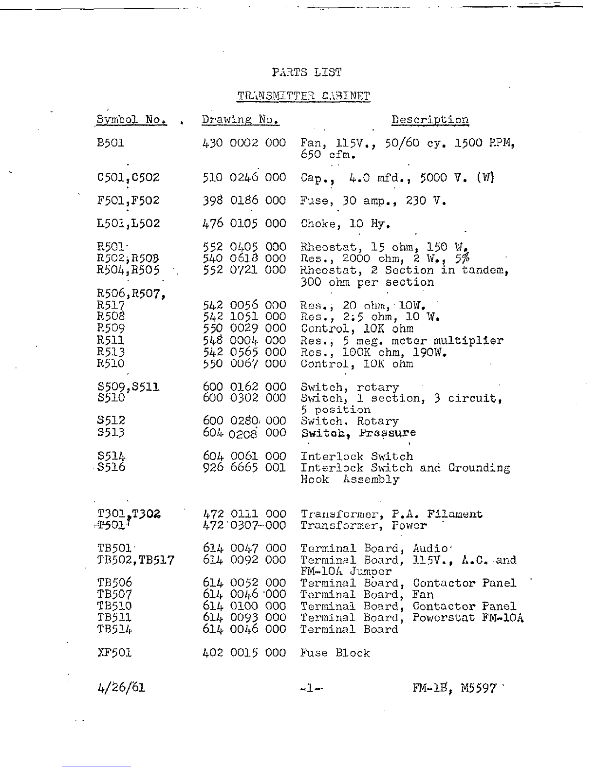
PARTS LIST
GUZZANT~
Page
1
2
3
4
4
5
6
8
9
9
10
PHOTOS
813 6026 001
DRAZINGS: 813
5901 001 Filter Installatioc
813
5904 001 Remote Control dring - RiiC-20OA.
813
5903 001 Remote Coz.trol &ring - RX-1OC.
A-31735-1
?iicrcmatch Cap Assy. and
iiCht?matiCi
A-31735-2 Micromatch Cap assy. and Schematic;'
B-65503 Schematic, Power Supply
B-67314-1 Recycle Unit Schematic
C-79128 Base Layout Izformztion
D-23115 Overall Schematic
D-23127 Internal biiring
M5534
EXCITZR INSTRUCTION BOOR
M5675
50 b/ATT AIQLIFI.&d INSTRUCTION BOr3E;
M5737
FILT&R INSTRUCTIONS
M6023 AUTOmTIC REGYCLZ UNIT INSTRUCTIONS
FACTORYT&ST DATA SHEETS.
4/26/61
-1.
FM-lB, M5597
I

S"%CIFICi\TIONS
Power Outpuf;:
Frequency Rang;:
R.F. Output Impedance:
Type of Oscillator:
Frequency Stability:
Type of Modulation:
Modulation Capability:
hudio Input Impedance:
m-1$
N559’z
1000 Watts
88 to 108 MC,
50
ohms
Direct Crystal Controlled
L .qol%
Rhase shift employing pulse techniques
f- 100 KC
75
KC considered 100% modulation
600 ohms
Audio Input Level for 100% Modulation: fl0 DBMk2 db
Frequency Respones: Within 1.0 db of standard.
75
micpo-
second pre-emphasis curve, or flat
L1.P db
50
to 15,~~;e~;;cps which-
ever is desired.
Distortion at 100%
Modulation: 1% or less
50
to 100 cycles
.5%
or less 100 to 10,000 cycles
1% or less 10,000 to 15,000 cycles
Noise:
Fowcr Input:
Tubes:
65 db below 100% modul.ation (FM)
50 db below equivalent lOO$ (AM)
modulation
230 volts;50/60 cycles, single phase
three wire, 5 KVii demand; 115 voltse
5OJ60
cyles single phase, 5+3Gwattsi :
z - Oh.2 - 6080
-
6146
i:..
: -
4-400/i
W3;4~R4
l- -
-
12xc7
R.F. Qutput Connector: 7/e inch coax flange
Size: Width - 24 in. (less end bells), 27 in,
(with end bells), Height - 78 in.
Depth -
364.
inch.
Wcightt Facked - 1140 lbs. Net 880 lbsr
Cubagel 34
CU.
ft. unpacked
4/26/61
-l- FM-lB t
~5597
DESCRIPTION
The Gates RPi-13 frequency mod,ulated bro&cast transmitter will
provide 1000 GJatts of fre,uency modulated $ower to a properly
designed antenna and transmission line system on any frequency
from 88 to 108.M~. Characteristics obtained, in any proper
installation, will exceed those required by the FCC for FM
broadcast service.
The basic units of the FPi-1B are: exciter, driver and power
amplifier.
a>
b)
Cl
The exciter unit (Yi5534) is capable of 10 watts
output and is the basic exciter used in all of
Gates Fi'i equipment.
The driver unit (Wj675) is capable of 50 vJatts
output and is link corri;led to the input of the
power amplifier,
The power amplifier of the PPi-1B consists of two
4-400s power tetrodes oloerated in a push-pull
circuit. kuarter-wave lines are employed in
the plate circuit for maximum stability and
efficiency;
The M5534 exciter used in this transmitter employs a phase shift
modulator with @se timing techniques and may be adapted to
single or dual channel multiplex&g on a plug-in basis, with
blank panel space provided for the addition of the multiplex
unit.
An important feature of this transmitter is the lack of frequency
multiplication after the exciter. This aids in helping to elim-
inate spurious frequencies and gives protection to tube life, as
power type tubes in doubling or tripling operation.are not always
operated at their most stable life lengthening conditions.
Mechanically the FE-lB has been designed to be e,asily maintained.
Ready accessibility to all parts is accom;ilished by lift-off
type doo.r.5. The sides of the cabinet may be easily removed
by removing two screws from the holding bracket from the bot-
tom of the side panels and lifting the side panels off..
The control panel for the FM-U consists of the OFF-ON switches,
for the line voltages, the OFF-ON switches for the plate voltage,
various indicator lights, the local remote switch, the tune
operate switch and the overload reset switch&.
The meter panel for the FM-1E is hinged and may be lifted Up by
first loosening the fastener one quarter turn using a screw-
driver or a coin and then lifting the meter panel up;. This
will give access to meter terminals and wiring of the reflecto-
meter or Micromatch switching section.
4/26/61* -2- Wi-13, M5597
..i_L~ ------.- .~.-_-_. .
TIDORY OP OP?XATION
With the pressing ef S502 the low voltage ON button, primary
voltage is applied to the exciter, the blower, the fan and the
low.voltage porc;er supply. Filament voltage is also applied to
both PA tubes; rectifier tubes,and voltage is applied to the
control circuitry. The exciter has its own power supply and
DC voltage is applied to the exciter when its power supply
.comes up to operating temperature. The exciter power supply
also supplies voltage for the driver screen. The low voltage
supply supplies voltages for the driver plate and the ampli-
fier screen. With switch S5l2 in the grid position, about a
minute after S5O2 is pressed grid current will appear on the
PA gird current meter, which is the
second
meter from the left
on the cabinet meter panel. This meter should indicate 16 to
25
mils of grid current.
The low voltage power supply also supplies the screen voltage
for the power amplifier, however, the DC path is broken through
a set of contacts on K503, which is the high voltage contactor.
By pressing the high voltage ON button S506 both plate and
screen voltage are applied to the power amplifier.
The function of
S518
is a "local-remote" switch,'with the switch
in the "remote" position the fail-safe relay in the remote con-
trol unit acts as the holding contacts for K501, which is the
line contactor. Faith S518 in the "local" position the holding
contacts on K501 are operative and the retiLote control unit is
disconnected from the transmitter.
The function of S5l.9 is the "tune operate" switch. In "tune"
position S519 disables the automatic recycling unit so the
transmitter is on complete manual control. The theory and
operation of the automatic recycling unit is covered in a
separate set of instructions which are part of this inetruc-
tion book.
The function of
S517
"overload reset" is the resetting of the
plate overload relay
K505.
If S519 is in the "tune" position
the transmitter experiences an overload,
S517
must be pressed
tu reeet
K505
before ?late voltage can again be ap@ied t& the.
amplifier.~ Overload relay K505 is in a "lock out" type of
circuit. If S519 is in the "opera%;e" position the resetting
of the plate overload is automatically taken care of in the
recycling unit.
To multiplex the Gates FM-1B is a relatively simple matter. The
main channel exciter was specifically designed with multiplex in
mind. Space has been provided directly below the exciter for the
placing of the multiplex unit. A minimum amount of connections
are necessary to connect this unit to the main channel exciter.
Connections necessary are a coax connector to the multiplex
exciter in the multiplex chain. This is done on the front panel
of the two units. Other connections necessary are power from
115 volt source. This can be taken off 115 volt terminals of
4/26/61.
-3-
FM-lB, M5597
~-
the main charnel exciter and the connecting of the audio to the
terminal board on the multiplex unit completes the necessary
wiring. The multiplex unit is capable of handling two sub-
channels and, therefore, there are two audio input terminal
arrangements available on the terminal board of the multiplex
unit. .
Since the power contactorsare non-circuit breaker types, they
require a momentary ON and a momentary OFF type of function ta.
operate them, the transmitter is easily remote controlled.
UNPACKING AND RRADYING FOR 0Pr;RaTION
The FM-1B is carefully checked and packed at the Gates plant
to assure that safe arrival at its destination in proper elec-
trical and mechanical condition.
Tests of many different kinds are made at the factory and the
unit is operated for several hours to assure correct adjustment
and proper operating conditions.
Certain large components are removed from the unit and shipped
separate to assure safe handling. The components removed are:
T501, L501, ~502,
c501
and
c502.
Wires are numbered or tagged
as a guide for replacement of these parts. Photographs are
supplied to assist in the proper placement and orientation of
the components that have been removed for shipment.
After the FPI-1B has been received and unpacked, it should be
carefully inspected for any mechanical damage. If any damage
is noticed to any section of the equipment, a claim should be
filed immediately with the delivering transportation company
and necessary replacement items ordered from the Gates Radio
Company.
It is a good precautionary practice to completely go over the
equipment to check for loose connections, loose components,
broken insulators, etc., that might have become loosened or
damaged in shipment. Make sure all relay contacts are free
and in good mechanical operation. Make sure all mechanical
connections are tight.
The power contactors are either tied down or blocked sufficiently
to keep them from vibrating during shipment. These should be
checked and the shipping material removed.
A
good overall visual inspection may save much time later in
getting the transmitter to operate correctly.
INSTALLATION
In advance of actual placement and adjustment of the transmitter
certain preliminary planning should be done. The use of drawing
C-79128 and 813 5901 001 will assist in locating the power and
audio input leads and the power output from the transmitter.
4/26/61. -4- FM-lB,
M5597~

The following should be arranged in advance of actual instal-
lation work.'
.l. Leads from a low rcactanct: dower source of 230
volts, 60 cycl?, single phase and 115 volts,
single phast, 60 cycle AC lines should be run
in conduit underneath th+ propos<;d location or
platform.
The wires she-uld be at least ,$6 for 230 volts,
60 cycle, sin,lc phase and &12 for the
115
volts,
63 cycle, sing12 Qhase for best regulation.
Zunning these powar sources in lead enclosed wires
or in a steel conduit is highly recommended to ob-
tain both audio and radio frequtincy shielding near
the transmitter.
2. To assist in kee-sing :RF currents in nearby audio
equipment to a minimum, a good ground at these
frequencies is mandatory. One of the best known
methods of doing this, is the installation of a
sheet of copper for the ground system beneath
the complete transmitter layout. RF usually
shows up in one or both of two ways, feedback
or high noise level. It should be pointed out
that even a small amount of xirt unshielded is
a very effective antenna at YH frequencies in
transferring i2F to the grid xhere it is recti-
fied and oasszd on as noise or feedback.' It is
preferablz to have a
from the transmitter
ground.
single common ground point
copper shield to a good
OP&ATING AND TUNE UP P~OC~DLJZE
Before attempting to tune thz
netted to a transmission line transmitter, make sure it is con-
and antenna that will present a
nominal load of
50
ok;ms or a non-reactive load with the proper
power bundling capabllitii:s.
Before tuning the transmitter, refer to the factory test data
sheets and ch=c'k all dial readings to corrosgond <lith the data
given on th? fxtory test data sheets.
Switch 5518 should be in the "local" position, switch S519
should be in the "tune" position.'
After the installation is corn;-lete all input and,output cables
have been connected xnd thr; crystal oven has be,-an operating for
two hours or more punching the low voltage llON1l button applies
primary voltages to all of the filaments, control circuits, the
fan, the blower and the low voltage power supplies. Provision
4/26/61..
-5-.
FM-lB,
M5597
is made on the driver panel for metering the grid bids voltdge
of thi driver oy tii~ns oi^ 2 tv;at yoirit or; th< front panel, Ji
meter such as a Simpson Kodel 260 or tikuivalent may be used.
Flith the negative l-ad. plugged into this test point and the
positive lead grounded, a rise in grid voltage will be observed
as the exciter comes up to op‘;rating ttimperature. This voltage
should be spproximatsly
15
to 20 volts. This is 2. good check
on the exciter operation. Plccz switch Sj1.2 which is the test
meter switch located on the bottom cdnti-r of th; amplifier
panel, in the grid position, which is extreme counterclockwise.
Tune the grid circuit to resonance with control marked "grid
tuning:' and observe &rid current on X532, this should be ap-
proxiAately 16 to 25 mils of grid current.
Press the high voltage Oi!Jbutton and tune the amplifier te
resonance with the control marked :'plate tune" and observe
plate current on meter Zj35. It may be necessary to go back
and re-resonate the grid circuit aftdr high voltage is applied.
Load the amplifier to thz req-aired pob:tr by the control marked
"RF output I' turning control clockwise increases loading and
counttirclockwisa decreases loading. Obstirve power output on
meter X505 which has been caiibrated at the factory and reads
power being dalivered out of the transmitter to the transmission
line. l'his meter h&s been caiibrated and its calibrating Gn-
trols locked in place and should not be tampered without express
authorization from t1;? Gates Radio Company.
NEU!CR1.~LIZ~~ICN
Tuning of an ITT transmitter in the frequency range of 88 to 108
~Mcs, offers greater difficulties in regard to tuning various
circuits than is normally encountered In the lower AM frequencies.
This is manifest in greater reaction between various circuits
caused by small inductive and capacitive reactances that can
normally be ignored at the lower frequencies, but which can
become incrensingly important at these high frequencies. There-'
fore, when t7uning a high frequGncy transmitter, it is well to
constantly re-check the previous adjustments as tuning progresses,
The transmitter hcs beon ,rop,r ly :lcutralized at the flctory on
the customer's frejutincy with a 50 ohm non-reactive load. Due
to rough handlinK during shipm.2n-t neutralization may be affected.
Improper neutralization is indicated by several abnormal condi-
tions showing up in thi optiration.
1. When the grid current does not rise to maximum or
near maximum simultaneously with a dip in &ate
current as the amplifier @a&tank is tuned through
resonance.
2. If excitation is remoired from the amplifier and
thi: PA grid relay dot;s not open, this indicates
oscillation in the power amplifier itself. This
4/26/61. -6 PM-D, M5597
-
self-oscillation productis grid current which
holds the grid relay K506 closed, this keeps
the plate voltage applied allowing. thz ampli-
fier to
continue
its self-oscillation.
3. If the baldnce control B504 and R505 does
not
enable the t;qo plate currents to maintain a
balance within 1096, this condition will indi-
cate improper neutralization.
4. A radical change in PA grid current from the
value given on the factory test data sheet.
5. Spurious radiation detected across the band.
The neutralizing controls have been brought out to thz front
panel of the amplifier to a special machined bushing. In the
center of this special bushing is a shaft with a machined
screwdriver slot. It will be noted that on both this special
bushing and the internal screwdriver slot shaft, there are
two black dots. These two dots are aligned in a vertical
position when the neutralizing capacitors are at maximum
capacity.
It will also be noted that on this special bushing is a red
dot which will appear directly o,,osite the black dot on the
movable portion of the shaft. This red dot, on the special
machined bushing, indicates the location of the neutralizing
capacitors as they were set at the factory. These marks will.
serve as a good starting place if complete re-neutralization
is required,
If any of the aforementioned conditions are observed when the
transmitter is first placed in operation, this indicates that
re-neutralization is in order. This is accomplished as follows:
1. Turn the high voltage OFF.
2. Remove the bottom cover from the PA tank.
3. Loosen the locking nuts on the Pear Of the
neutralizing capacitor slightly, so that
the capacitor shaft will turn free with a
slight drag on the shaft.
4. Remove one of the plate caps from the
high
voltage rectifier, so as to reduce the plate
voltage.
5. Replace thd bottom cover plate on the amplifier
tank.
6. Apply low plate voltage and adjust either
C303 or C308 in one direction and again
check for neutraiization.
4/26/61. -7- FH-lB, M.5593

7.
If imurovtiment r?sults, adjust thG othcs
capacitor thti sac amount in t!i~ sfiti
diraction and again re-chock for noutrali-
zation.
8. Continue this procxlure step-by-step rotating
capacitor
C307
and C308 in the dirsdtion that
indicsttis the proper neutralization.
9. Replace the cap removed on the high voltage
rectifier for normal operation and re-check
neutralization.
1.0. Remove the bottom cover of the iimplifizr t&T&
and re-tighten thz locking nuts on thi rear
5 of the neutralizing capacitors, being careful
dot to move th? adjustment Whil- thSse locking
nuts are being tightened.
There are some fxts about ths 2owtir amglifior that should by
known
zd rem,-mber=d that i*jill hzlp in good optiration of the
equipment and contribute to bust operating results.
*Tuning of th? platti circuit chr;n+e the effGctivti electrical
length of tha plate tank. Increasing the s_;acing between the
tuning and th,- plate tank lintis lc-ngthcns the tiffectiva length
of th+ plztz tank and lowers the frz%uency; dacraasing the
spacing will raise thti frequcncg.
. Switch
S510
located on thz por;:tir amplifier pan;1 in tht: lower
ltift had corntr is providtid for chacking individual cathode
currtints of V301 and V302 as wall as tkie totz;l plate clJj-re&
on both th=;-si tubes..
The ballnct control X504 and
R505
is provided on th= front
panel to enable the operator to Laintain a balance in plate
currents I
3510 is used for relative balance indication of plate currents.
This switch must be left in the normal or mid-position while
the transmitter is ocsratinfi, except on i.nitial tune up or for
checkin. balance bstwecn alate currents of the tubes.
S512
is a muxtineter srritch which is used to rend either- total :
control grid curr-+nt or individual screen grid currents of
V301 and
V302..
Z’.
4/26/61.
-8-
PM-15,
M5597
Protection against electrical shock from high voltage circuits
are provided for by the door interlock switch S514. By re-
moving thi back door, 5514 will open and immediately remove
the high voltage from the amplifier. Forced air is provided
for the amplifier tubes by a blower B301. B501 is provided
to exhaust any hot air in the cabinet proper.
MICROMATCHOPERATION
On Drawing A-31735-2 is a complete schematic of the internal
wiring for the Micromatch unit. The following is a descrip-
tion of this unit as used with the FM-1B transmitter.
On the Micromatch switching panel there are two controls which
adjust the calibrating of the unit and a switch. One control
has a knob which is the VSWRcalibrating control, the other
has a shaft lock. The control with the shaft lock adjusts the
calibrating of the power function and is set at the factory and
needs no further adjustment. The other control with the knob
adjusts the calibration of the VSWR.
To calibrate the VSWRportion of the unit turn the switch to
calibrate position and adjust the meter to full scale deflec-
tion using the control with the knob. Turn the switch to V&R
position and read the standing wave ratio on the lower scale of
the meter.
To read forward power or power being delivered out of the trans-
mitter to the transmission line, turn the switch to forward
position and read power directly on M505,
RXMOTdCONTROL
All necessary provisions for remote controlling the Gates FM-1B
are built into the equipment.
1. Remote plate voltage is obtained from TB503
terminal 8 and is controlled by R521,
2. Remote plate current is obtained from TB50+7
and is controlled by R520.
3.
The "LINE ON" function from the fail-safe relay
in the remote control unit is connected to
TB503-2
and TB503-3.
4. The piate ON function is connected b&ween TB503-5
and TB503-6. &move the jumper between the TB503-4
and TB503-5 for remote operation. Its function re-
quires a momentary "on" type of function.
5. The plate OFF function is connected between TB503-5
and TB503-4. This function requires a momentary "off"
type of function.
-6/61.
-Y-
FM-lB,
Pl115597

6. The remote overload reset function is
connected
between TB503-9 and TB503-10. This connection
is 6 volt DC from a stepper position on the re-
mote control unit.
7. The raise-lower functions are connected to TBl-1
and TBl-3 on the motor driven rheostat (M4703C
for remote control of
tower OUtpUt).
In the
case
of the Gates RDC-lOC, one side of the
115 V. primary voltage for the motor of M4703C is
connected between TBlOl-7 on the exciter terminal
board in the transmitter and TBl-2 on M4703C. The
other side of the 115 V. AC line is connected
to
the common of the remote control unit which is
TB2-27.
MAINTRNANCE
Maintenance of the PM-1B should consist of periodic checking
of tubes, meter readings, cleaning and visual inspection,
lubricating places where required.
The use of air filters materially assists in keeping the trans-
mitter interior clean, however, p
eriodic removal of dust will
still be necessary. Since electrostatic seals create dust-
catchers? special attention should be paid to these places.
Support
Insulators for the tank tilements are probably the
worst offenders and must be kept clean and free from all
foreign material. Failure to do so may result in arc-over
and shattering of the insulators. When inspection of the
air filter discloses that it is filled with dust or foreign
matter they should be discarded and replaced with a new one.
The type of filter used in the FM-1B is a disposable type
filter and is obtainable from most any local hardware or
appliance store.
Once a month the blower and exhaust fan should be cleaned
and checked for proper operations. A few drops of light
machine oil should be dropped in the oil holes provided at
each end of. the blower motor,..-%h* exhaus F ffl..YPhae--Se&&
bearings and needs no attention.
Once a month the entire transmitter should be cleaned of dust.
In the case of the power amplifier, remove the back cover and
the enclosure should be wiped clean of dust. The two protective
relays should have the. dust cleaned as required and.contacts
burnished with a burnishing tool. Each relay is protected with
a dust cover and are telephone type relays and will require little
or no attention.
This transmitter is a precision electrical device and as such,
should at all times be kept clean and freti from dirt ad dust.
Dust shortens the life of many components due to flashovers,
arcs, etc., which damage the same. A small brush or soft rag
can be used very effectively in keeping the equipment clean.
A good preventative maintenance schedule will provide best
assurance of trouble-free transmitter operation.
4/26/61. -LO- FH-lB, Pi5597
S;mbol No. .
B501
C501,c502
F501
,F502
L501,L502
510 0246 000
398 0186 000
476 0105 000
R501. 552 0405 000
R502jR5OS 540 0618 ooo
R504, R505 552 0721 000
R506,R507,
R5l7
R508
R509
R5ll
R513
R510
S512
S5U
5514
S516
TB501.
TB502,TB517
TB506
TB507
TB510
TB511
TB514
xF501
PARTS LIST
TR.',NSMITTE!?C.\BINET
Drawing No. Description
430 0002 000 Fan, 115V.,
650 cfm. 50/60 cy. 1500 RPM,
542 0056 000
542 1051 000
550 0029 000
548 0004 000
542 0565 000
550 0067 000
600 0162 000
600 0302 000
600 0280~ 000
604 020~' 000
604 0061 ooo
926 6665 001
472 Olll 000 Transformer, P.A. Filament
472'0307-.OOO Transformer, Powcr
614 0047 ooo
614 0092 000
614 0052 000
614 0046~000
614 0100 000
614 0093 000
614 0046 ooo
402 0015 000
Terminal Board, Audio.
Terminal Board, 115V., h.C, and
FM-1OA Jumww
Terminal Board, Contactor Panel
Terminal Board, Fan
Terminal Board, Contactor Pane1
Terminal Board, Powcrstat FM-1Oir
Terminal Board
Fuse Block
Cap.,’ 4.0 mfd.l 5000v. (WI
Fuse, 30 amp., 230 V.
Choke, 10 Hy.
Rheostat, 15 ohm, 3.50 $,
Res., 2000 ohm, 2 W.,
Rheostat, 2 Section in tandem,
300 ohm per section
",e;.; 20 ohm;lOlrf.
e ., 2;5 ohm, 10 w,
Control, 10K ohm
Res.,
5 meg. meter multiplier
RCS.,
1OOK ohm, 19OW.
Control, 10K ohm
Switch, rotary
Switch, 1 section, 3 circuit,
5 position
Switch. Rotary
Svitol;, Pressuse
Interlock Switch
Interlock Switch and Grounding
Hook Assembly
-le.
FM-q iy5597
c3vmbolNo.
MiOl .
M502
MS03
M504
M505
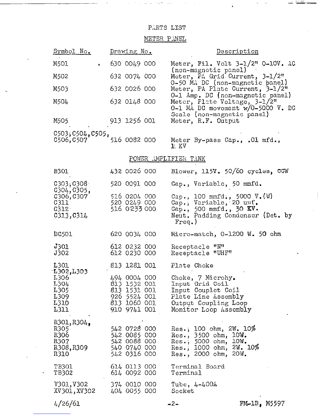
P,;RTS LIST
Drawing No. Description
630 0049 000
Meter, Fil. Volt 3-l/2" 0-LOV. AC
632 0074 000 (non-magnetic panel)
Meter, PA Grid.Current, 3-l/2"
632 0026 000 O-50 MA DC (non-magnetic panel)
Meter, PA Flatc Current, j-1/2"
632 0148 000 O-l Amp. DC (non-magnetic panel)
Meter, Flate Voltagc,,3-l/2"
O-l MA DC movement w/O-5000 V. DC
913
1256 001 Scale (non-magnetic Panel)
Meter, R.F. Output
c503;c504,c&
C506,C507
'516 0082 000 ye;? By-pass Cap., .Ol mfd.,
I
PU>ER .%?LIFI!& TANK
B301
C303jC308.
c304,c305,
C306,C307
C311
C312.
c312,c314
DC501
d301
5302
L3OL
.L302,L303
L306
1,304
L305
L309
L310
R301,R304,
a305
R306
R307
EWE&,"309
TB301 614 0113 000 Terminal Board
TB302 614 009% 000 Terminal
V303.,V302
374 0010 000
Tube, 4-40011
XV3Ol,XV302
404 0055 000
Socket
4/26/6X -2- FM-lB, hI5597
432 0026 000
520 0091 000
516 0204 ooo
520 0249 000
516 0'233 000
620 0034 000 Yiicro-match, O-1200 W. 50 ohm
612 0232 000
612 0230 000 Receptacle 'IN"
Receptacle "UHF"
494 0004 000
813
1532 001
f313 1531 001
926 5524 001
813 1060 001
916 9741 001
542 0728 000 i3es.j 100 ohm, 2vJ. 10%
542 0085 000
542 0088 000 Res., 3500 ohm; 1OW.
Res.; 5000 ohm, 1OW.
540 0740 000
542 0316 000 Res.; 1000 ohm; 2W. 10%
Res., 2000 ohm, 20W.
Blower, 115V. 50/60 cycles, fxw
cap.,
Cap.,
Cap.;
Cap.,
Neut .
-
100 mzfd; , 5000 V. (i:I)
Variable;20 u11f.
500 mmfd., 30 KV.
pdding Condenser (Det. by
F'req.,
Variable, 50 mmfd.
Plate Choke
Choke, 7 Microhy,
Input Grid Coil
Input Couplet Coil
Plate Line &xsembly
Output Coupling Loop
Monitor Loop iascmbly

-
-_-
Sirmbol No.
PARTS LIST-
CCNTROLI7iNEL
Drawin No. Dosn--iption
h5ol;ii505,k506,
L507,8508
396 0105
000 Lamp, 14 V.
L503 396
3062
000 Lamp, Neon
S502,S506
s503,s507
s517.
S5lr3,S519
xz501
XA503
xA505,Xk506;
xi;507,XA508
CR501,
CR502
K5Ol,.K503
K502.
K505,K506
K50V
R514
R515
R516.
R520,R521
T502
.+T%s&
TB50&TB505
TB513
TB515
TB516
v501,v502
xv501,
Xv502
540
0202
000 Res., 1OOK ohm, 1/2W. 10%
604
604
0067 000
0069 Switch; Pushbutton; Black
000
604 Pushbutton, Red
0150
Switch,
ooo
O.L. %esct Pushbutton Switch
604 0032 000 Toggle Switch, D.7.D.T.
406 0052
000 Pilot0051 Light Green
406 000 Bsscmbly,
Pilot Light iisscmbly, Red
406 0053 ooo Pilot Light .&ssembly, !rmber
CCXT.;CTOiL.P:iNZL
386 0015 ooo Silicon Diode, 10 V,
570 0055 000
574 0074 OGO jcB";$t&-; ftc.,p~~~.,,z~jyy=.
23Ov.
572 0025
000 Relay;
2-c
574 0014
000 Relay, 6V. D.C.1 S.P'.D.T.
542 0056
000 Xes.,
20
ohm, 1OW.
542 0085
000 Res., 3;5K ohm, 101~;
550 0061 ooo Control, 1K ohm;ZW,
550 0057 000 Control, 250 ohm, 2W.
472 0112
000 Transformer, Rect. Fil,
614 0054
000 Terminal Board
614 0104
000 Terminal Board.
614 0034 000 Terminal Board, O.L. Relay Deck
614 0092 000 Terminal Board
614 0094 000 Terminal Board
374 0027 000 Tube, 673
404 0121 000 Socket
4/26/61 -3- FM-lB, M5597:
Other Gates Transmitter manuals


