manuals.online logo
Brands
  1. Home
  2. •
  3. Brands
  4. •
  5. Alpine
  6. •
  7. Automobile Accessories
  8. •
  9. Alpine RSE-K100SC Manual

Alpine RSE-K100SC Manual

Other Alpine Automobile Accessories manuals

Alpine eX-10 User manual

Alpine

Alpine eX-10 User manual

Alpine HCE-C1100 User manual

Alpine

Alpine HCE-C1100 User manual

Alpine eX-10 Instruction Manual

Alpine

Alpine eX-10 Instruction Manual

Alpine KCX-C2600B User manual

Alpine

Alpine KCX-C2600B User manual

Alpine KCE-400BT User manual

Alpine

Alpine KCE-400BT User manual

Alpine HCE-C1100 User manual

Alpine

Alpine HCE-C1100 User manual

Alpine KTX-CMY8-S User manual

Alpine

Alpine KTX-CMY8-S User manual

Alpine PSS-21WRA User manual

Alpine

Alpine PSS-21WRA User manual

Alpine RUE-BK01A User manual

Alpine

Alpine RUE-BK01A User manual

Alpine HCE-C117D User manual

Alpine

Alpine HCE-C117D User manual

Alpine KTX-WXE-M38 User manual

Alpine

Alpine KTX-WXE-M38 User manual

Alpine HCE-C114 User manual

Alpine

Alpine HCE-C114 User manual

Alpine KTX-PRS8-S User manual

Alpine

Alpine KTX-PRS8-S User manual

Alpine KTX-FPU8 User manual

Alpine

Alpine KTX-FPU8 User manual

Alpine KTX-CMO User manual

Alpine

Alpine KTX-CMO User manual

Alpine KTX-GM7-O User manual

Alpine

Alpine KTX-GM7-O User manual

Alpine HCE-C115 User manual

Alpine

Alpine HCE-C115 User manual

Alpine KTX-RV48-S User manual

Alpine

Alpine KTX-RV48-S User manual

Alpine HCE-C300R User manual

Alpine

Alpine HCE-C300R User manual

Alpine HCE-C125 User manual

Alpine

Alpine HCE-C125 User manual

Alpine HCE-C105 - Rear View Camera System User manual

Alpine

Alpine HCE-C105 - Rear View Camera System User manual

Alpine i509-WRA-JL User manual

Alpine

Alpine i509-WRA-JL User manual

Alpine HCE-C104 User manual

Alpine

Alpine HCE-C104 User manual

Alpine KTX-WXE-CA8 User manual

Alpine

Alpine KTX-WXE-CA8 User manual

Popular Automobile Accessories manuals by other brands

Magneti Marelli AC161 Installation instruction

Magneti Marelli

Magneti Marelli AC161 Installation instruction

FDI uEZ GUI Start here

FDI

FDI uEZ GUI Start here

JCROffroad JT Install instructions

JCROffroad

JCROffroad JT Install instructions

Rostra VOXXElectronics 250-1930 owner's guide

Rostra

Rostra VOXXElectronics 250-1930 owner's guide

TOP VEHICLE TECH GR3FORD5 installation manual

TOP VEHICLE TECH

TOP VEHICLE TECH GR3FORD5 installation manual

Safe Fleet PRIME DESIGN AR-2000-BLK manual

Safe Fleet

Safe Fleet PRIME DESIGN AR-2000-BLK manual

Skoda Fabia Combi 5J Fitting instructions

Skoda

Skoda Fabia Combi 5J Fitting instructions

Camcar 40077 Al Mounting instructions

Camcar

Camcar 40077 Al Mounting instructions

Camcar 40089 AL Mounting instructions

Camcar

Camcar 40089 AL Mounting instructions

Impac Tradesman 2000 installation manual

Impac

Impac Tradesman 2000 installation manual

DVB OFFROAD BRSB-01 installation manual

DVB

DVB OFFROAD BRSB-01 installation manual

Safari Snorkel SS385HF installation guide

Safari Snorkel

Safari Snorkel SS385HF installation guide

ULTIMATE SPEED 279746 Assembly and Safety Advice

ULTIMATE SPEED

ULTIMATE SPEED 279746 Assembly and Safety Advice

SSV Works DF-F65 manual

SSV Works

SSV Works DF-F65 manual

ULTIMATE SPEED CARBON Assembly and Safety Advice

ULTIMATE SPEED

ULTIMATE SPEED CARBON Assembly and Safety Advice

Witter F174 Fitting instructions

Witter

Witter F174 Fitting instructions

WeatherTech No-Drill installation instructions

WeatherTech

WeatherTech No-Drill installation instructions

TAUBENREUTHER 1-336050 Installation instruction

TAUBENREUTHER

TAUBENREUTHER 1-336050 Installation instruction

manuals.online logo
manuals.online logoBrands
  • About & Mission
  • Contact us
  • Privacy Policy
  • Terms and Conditions

Copyright 2025 Manuals.Online. All Rights Reserved.

Renault Scénic
Stand vom 22.12.09 Version 1.0/
Deckenmonitor-Einbaukit
Installation kit for Rear Seat Entertainment
RSE-K100SC
Kit d'assemblage pour écran de plafond
Copyright MS Design - Autotuning GmbH
C1/12
Montageanleitung/ Mounting instructions/ Instructions de montage/ Instrucciones de montaje
Kit de instalación para monitor de techo
Teilenummer/ Part number/ Référence/ Referencia
Änderungen des Lieferumfangs vorbehalten/ Equipment supplied is subject to alteration/ Ce produit est sujet à modifications sans préavis/ Sujeto a modicaciones sin previo aviso
1) 2)
4)
3)
5) 6) 7) 8)
9)
DDGB
Pos. Bezeichnung Anzahl
1. Rahmen 1x
2. Halterung 1x
3. Schnittschablone 1x
4.
5. Niete 5,0x12 6x
6.
7.
8.
9. Ringkabelschuh 1x
Ringkabelschuh 1x
Parallelverbinder 1x
Quetschverbinder 4x
Kabelbinder 5x
Item Description Quantity
1. Frame 1x
2. Mount 1x
3. Cutting template 1x
4.
5. Rivet 5,0x12 6x
6.
7.
8.
9.
Ring connector 1x
Quick slide connector 1x
Butt connector 4x
Cable tie 5x
Harness (extension) 1x
FR
Item Description Quantité
1. Garniture 1x
2. Entretoise 1x
3. Gabarit de découpage 1x
4.
5. Rivet 5,0x12 6x
6.
7.
8.
9.
Cosse annulaire 1x
Clip rapide 1x
Cosse 4x
Collier 5x
Faisceau (extension) 1x
Copyright MS Design - Autotuning GmbH
C2/12
ES
Item Descripción Cantidad
1. Marco 1x
2. Soporte 1x
3. Plantilla 1x
4.
5. Remache 5,0x12 6x
6.
7.
8.
9.
Terminal de anilla 1x
Conector rápido de presión 1x
Conector de empalme 4x
Brida de plástico 5x
Cableado (prolongación) 1x
Montageanleitung/ Mounting instructions/ Instructions de montage/ Instrucciones de montaje
Stückliste / Parts list/ Liste de pièces/ Lista de componentes
a) b)
DDGB
Pos. Bezeichnung Anzahl
a) DVD-Deckenmonitor 1x
b) Kabelbaum 1x
c) Fernbedienung 1x
d) Kopfhörer 1x
e) Batterien 4x
f) Schraube TB 3x8 6x
g) Schraube CM 4x8 4x
Item Description Quantity
a) DVD Overhead Monitor 1x
b) Harness 1x
c) Remote Control 1x
d) Headphone 1x
e) Batteries 4x
f) Screw TB 3x8 6x
g) Screw CM 4x8 4x
Im PKG Monitor Set enthalten / Included in PKG Entertainment Package/
d) e)
f) g)
c)
FR
Item Description Quantité
a) Moniteur DVD plafonnier 1x
b) Faisceau 1x
c) Télécommande 1x
d) Casque 1x
e) Piles 4x
f) Vis TB 3x8 6x
g) Vis CM 4x8 4x
Copyright MS Design - Autotuning GmbH
C3/12
ES
Item Descripción Cantidad
a) Monitor de techo DVD 1x
b) Cableado 1x
c) Mando a distancia 1x
d) Auriculares inalámbricos 1x
e) Pilas 4x
f) Tornillo TB 3x8 6x
g) Tornillo CM 4x8 4x
Montageanleitung/ Mounting instructions/ Instructions de montage/ Instrucciones de montaje
Inclus dans l'emballage de l'écran PKG/ Incluido en el embalaje del PKG
5mm
Werkzeuge / Tools/ Outils
iso
Copyright MS Design - Autotuning GmbH
C4/12
D GB F
Bitte die Montageanleitung vor Beginn
sorgfältig lesen.
Wir empfehlen die Montage in einer
Fachwerkstatt durchführen zu lassen.
Please read fitting instructions
thoroughly before commencing
installation.
We recommend that fitting is carried out
by a specialist workshop.
Lire attentivement la notice de
montage avant de commencer.
Nous recommandons de confier le
montage à un professionnel.
ES
Por favor lea minuciosamente las
instrucciones de montaje antes de
comenzar con la instalación.
Sugerimos que el montaje sea realizado
por un especialista.
Montageanleitung/ Mounting instructions/ Instructions de montage/ Instrucciones de montaje
Kreppband/
Crepe tape/
Adhésif papier/
Cinta adhesiva
Bohrmaschine/
Drill/
Perceuse/
Taladro
Cutter-messer/
Cutter knife/
Cutter/
Cuchilla
Schraubendreher torx T27;T30/
Screwdrivers torx T27;T30/
Tournevis Torx T27;T30/
Destornillado Torx T27;T30
Schraubendreher PH2/
Screwdriver PH2/
Tournevis Cruciforme Ph2/
Destornillador PH2
Crimpzange für isolierte verbinder/
Crimping tool for isolated connectors/
Pince à sertir pour cosses ISO/
Alicate de engastar terminales aislados
Nietzange/
Rivet gun/
Pince à rivets/
Remachadora
Kunststoffkeil/
Plastic wedge/
Cale en plastique
Sacagrapas
2
D
1. Innenraumleuchte und hintere Spiegeleinheit
ausclipsen.
2. A-Säulenverkleidung vorsichtig ausclipsen.
3. Seitliche Abdeckung demontieren.
1
3
Copyright MS Design - Autotuning GmbH
C5/12
Montageanleitung/ Mounting instructions/ Instructions de montage/ Instrucciones de montaje
GB
1. Unclip the interior lamp and the rear seat mirror.
2. Unclip the A-pillar cover carefully.
3. Dismount the side cover.
ES
1. Quitar la lámpara interior y el espejo retrovisor.
2. Quitar el plástico del pilar-A con cuidado.
3. Desmontar la tapa lateral.
FR
1. Dé-clipper l'éclairage intérieur ainsi que le miroir
de vision des passagers arrière.
2. Dé-clipper délicatement le montant latéral
gauche.
3. Retirer le capot latéral gauche de la planche de
bord.
5
6
D
44. Abdeckung unter der Handbremsbetätigung mit
geeignetem Werkzeug ausclipsen. Deckel des
unteren Ablagefachs entnehmen.
5. 2x Torx-Schrauben lösen und Handbrems-
Betätigung entnehmen.
6. Seitlich die gezeigten Torx-Schrauben entfernen.
Copyright MS Design - Autotuning GmbH
C6/12
Montageanleitung/ Mounting instructions/ Instructions de montage/ Instrucciones de montaje
GB
4. Unclip the cover under the handbrake. Dismantle
the lower console.
5. Remove both screws and dismount the control
parking brake switch.
6. Remove the shown torx-screws on the side.
ES
4. Quitar la tapa de debajo del freno de mano.
Retirar la parte inferior de la consola.
5. Soltar los dos tornillos y desmontar el interruptor
de parking.
6. Soltar los tornillos Torx visibles en el lateral.
FR
4. Dé-clipper la trappe située sous le frein à main.
Démonter la console inférieure.
5. Retirer les deux vis puis démonter le panneau de
commande de frein à main.
6. Retirer les vis torx situées sur le coté comme
indiqué.
9
D
7
8
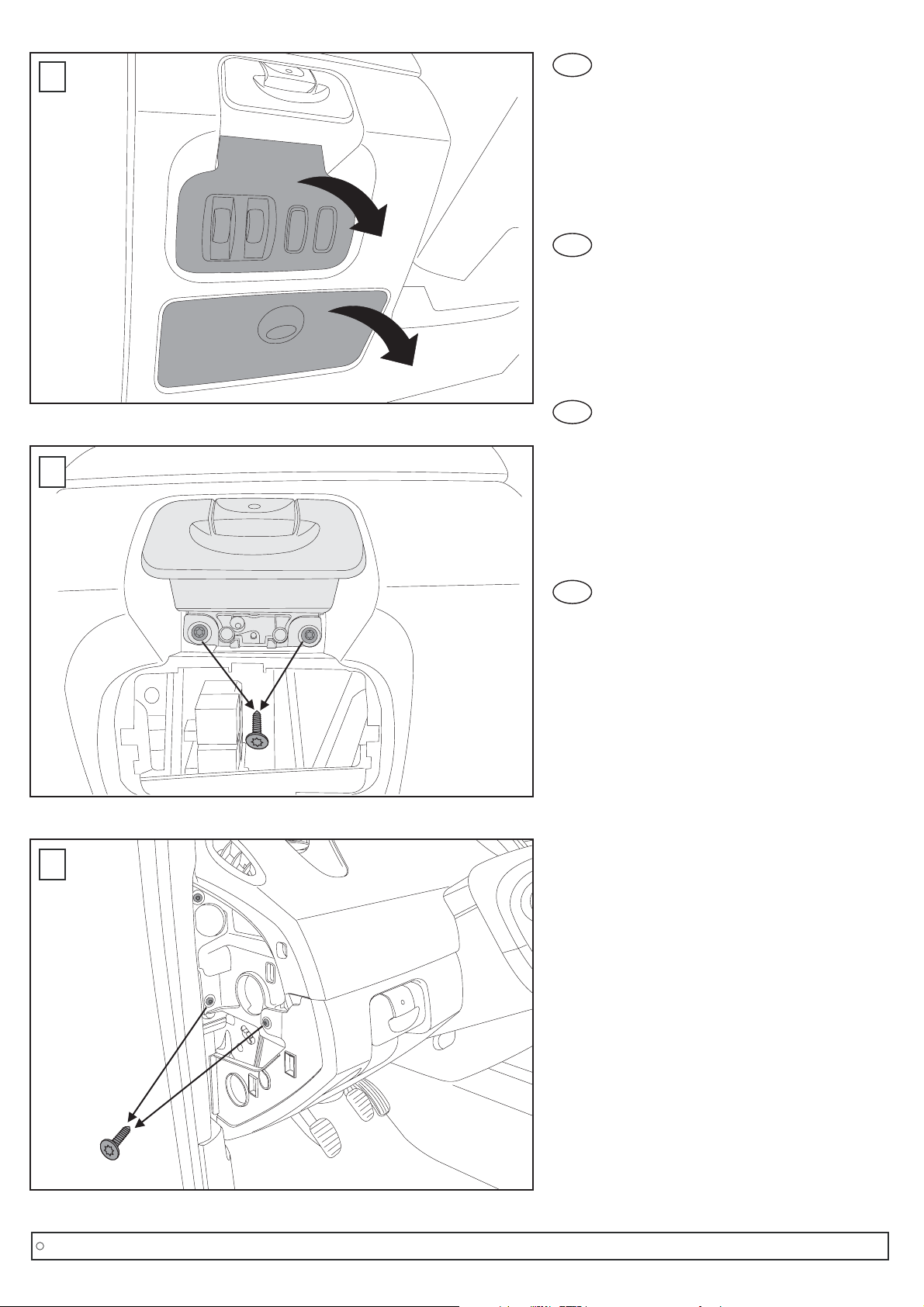
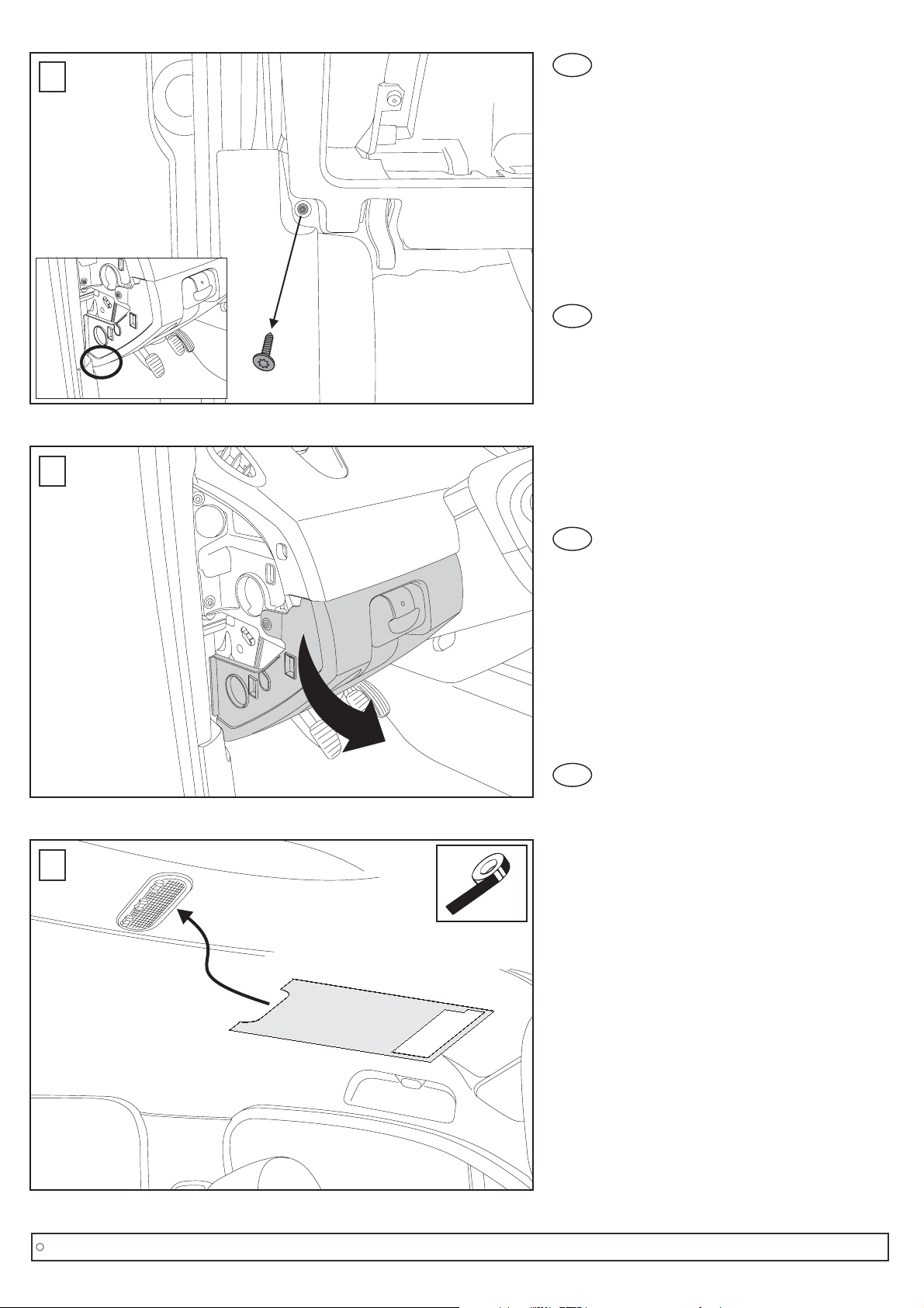
7. Schraube links unten lösen.
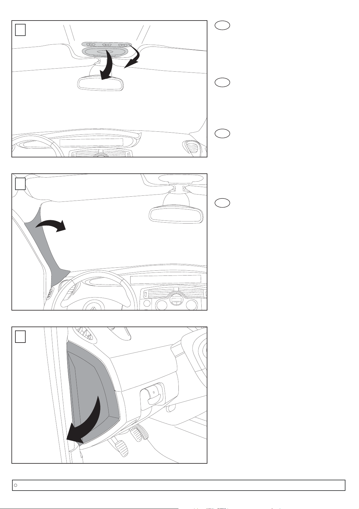
8. Untere Armaturenverkleidung beginnend von
links ausclipsen. Die Verkleidung kann jetzt ein
Stück nach vorne gezogen werden, um den
Sicherungskasten leichter zu erreichen.
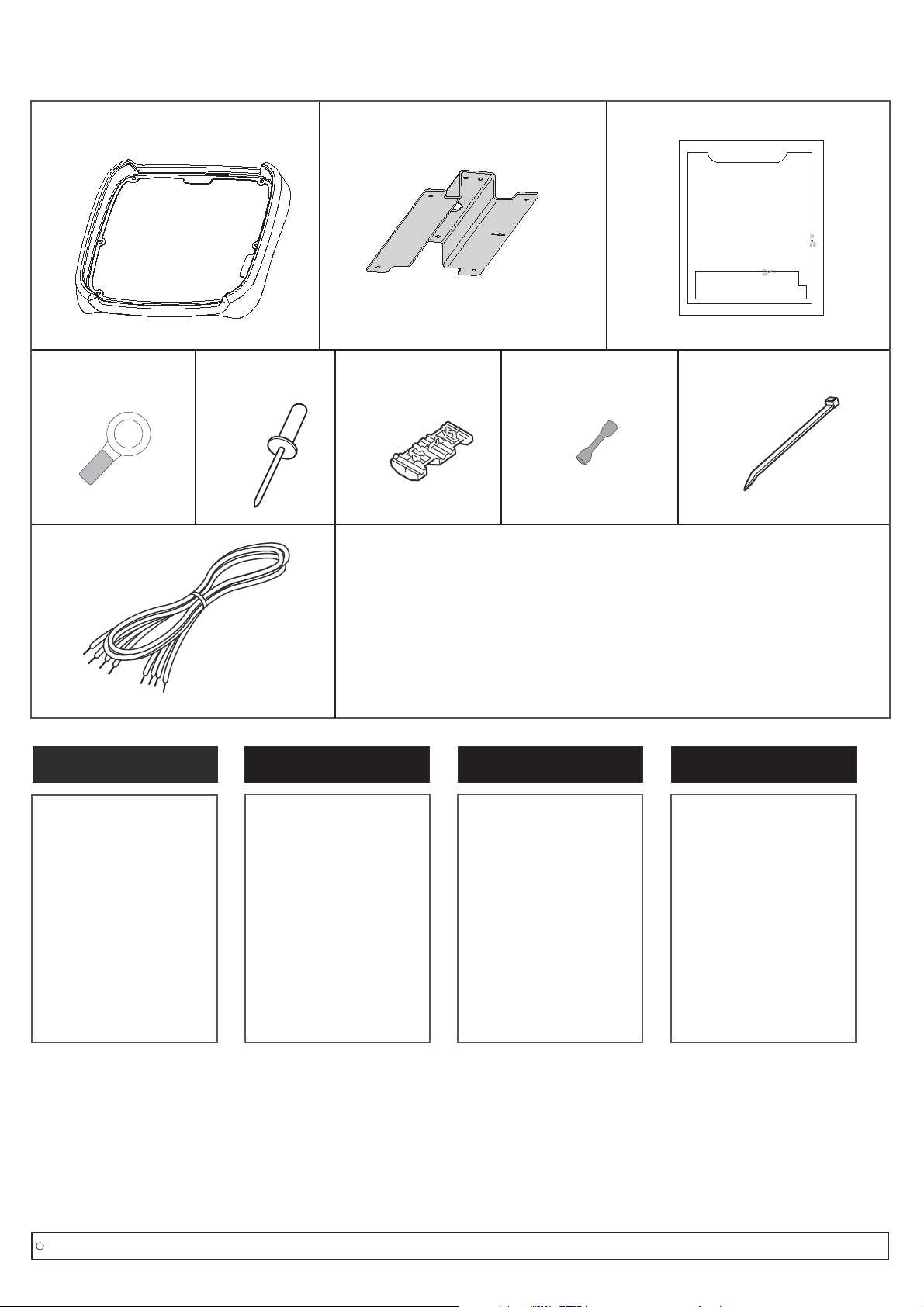
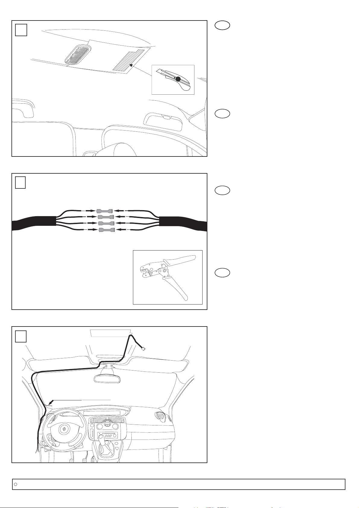
9. Mitgelieferte Schablone (3) ausschneiden, am
Himmel positionieren (kann ein wenig unter die
Abdeckung der hinteren Innenraumleuchte
geschoben werden) und mit Kreppband fixieren.
Nach dem Fixieren nochmals nachmessen, ob
die Schablone mittig sitzt.
Copyright MS Design - Autotuning GmbH
C7/12
Montageanleitung/ Mounting instructions/ Instructions de montage/ Instrucciones de montaje
GB
7. Remove the below screw on the left.
8. Unclip the dashboard cover on the left side. You
can’t remove the cover completely. It can be
pulled forward to allow you to reach the fuse box.
9. Cut out the provided template (3). Position the
template on the roof’s interior. Put a little bit of the
template under the interior lamp cover and fix it
with crepe tape. After that check the right position
again.
ES
7. Soltar el tornillo inferior de la parte izquierda.
8. Quitar el plástico del salpicadero ubicado en la
parte izquierda. No puede extraer el plástico
completamente. Se puede tirar de el para permitir
alcanzar la caja de fusibles.
9. Cortar la plantilla suministrada (3). Posición de la
plantilla en el interior del techo. Poner una
pequeña parte de la plantilla debajo de la luz de
cortesía y fijar con cinta adhesiva. Después de
esto, comprobar su correcta posición.
FR
7. Retirer la vis située sur la gauche comme
indiqué.
8. Dé-clipper la partie inférieure gauche du tableau
de bord. Elle ne peut par être retirée
complètement mais peut être repoussée de
manière à atteindre la boîte à fusibles.
9. Positionner le gabarit de découpage fourni (3), le
caler soigneusement en le coinçant légèrement
dans le support de l'éclairage intérieur. Ensuite, le
fixer à l'aide de l'adhésif papier.
1
2
3
44
3
1
2
iso
1: Gelb/ yellow/ jaune/ amarillo
2: Rot/ red/ rouge/ rojo
3: Schwarz/ black/ noir/ negro
4: Grün/ green/ vert/ verde
D
11
10
door/ green
Tür/ grün
door/ vert
puerta/ verde
12
D
10.
11.
12.
Wie im Bild gezeigt, den inneren Bereich mit
einem geeigneten Messer ausschneiden.
Darauf achten, dass die Dachhaut nicht
beschädigt wird.
Den im PKG-Set enthaltenen Kabelbaum (b) mit
der mitgelieferten Verlängerung (9) unter
Verwendung der Quetschverbinder (7)
verlängern.
Übersicht Kabelverlegung.
Copyright MS Design - Autotuning GmbH
C8/12
Montageanleitung/ Mounting instructions/ Instructions de montage/ Instrucciones de montaje
GB
10.
11.
12.
As shown in the picture, cut out the inner area
with a suitable knife.
Be careful not to damage the roofing.
Extend the harness (b) from the PKG-kit with the
supplied extension-harness (9).
Use the butt connectors (7).
Wiring diagram.
ES
10. Como indica la figura, cortar el área interior con
una cuchilla.
Mucho cuidado con no dañar el techo.
11. Prolongue el cableado (b) del kit del PKG con los
cables de extensión suministrados (9).
Use los terminales tubo de empalme (7).
12. Diagrama de cableado.
FR
10. Comme indiqué dans le dessin 10, découper
délicatement la partie intérieure à l'aide d'un
cutter. Attention à ne pas endommager le
pavillon.
11. Procéder à l'extension du faisceau (b) du PKG
avec le faisceau fourni (9). Pour cela utiliser les
cosses à sertir (7).
12. Schéma de câblage.
13
Kabelseite
12 222 2
111 1
STUV W
11
BPT
BP76 4A 5A
BPT3
3
AB
22
3
2
1
4B 5B
2F 2G 2H 2K 2L 2M 2N 2O 2P 2R
SP16 SP12 BP12
1F 1G 1H 1K 1L 1M 1N 1O 1P 1R
SP15 SP2 SP17 BP76 BP55 BP70 BCP3 BP32 BP25 BP77
SP16 SP3 BP11 BP87
12
C1D22
1E
AP43 AP1A SP16 SP4G BPS1 BP3 15LP 15RP
MAM
ACC
BATT
14
iso
ground/ black
Masse/ schwarz
masse/ noir
masa/ negro
15
DD
13. Den gezeigten Sicherungskasten entriegeln.
14. Das rote Kabel vom mitgelieferten Kabelsatz mit
dem gelben Kabel vom Steckplatz SP4G
(Sicherung T) und das gelbe Kabel vom
Kabelsatz mit dem roten Kabel vom Steckplatz
SP2 (Sicherung G) verbinden.
Es wird empfohlen, die Kabel durch
Löten zu verbinden.
15. Den Ringkabelschuh (4) am schwarzen
Massekabel aufcrimpen.
Hinweis:
Copyright MS Design - Autotuning GmbH
C9/12
Montageanleitung/ Mounting instructions/ Instructions de montage/ Instrucciones de montaje
GB
13. Unlock the shown fuse box.
14.
15. Crimp the ring connector (4) to the black ground
cable.
Connect the red cable with the yellow one from
the slot SP4G (Fuse T) and the yellow cable from
the harness with the red cable from the slot SP2
(fuse G) of the fuse box.
We recommend soldering.Note:
ES
13. Abra el compartimento de fusibles que se
muestra en la imagen.
14. Conectar el cable rojo con el amarillo de la ranura
SP4G (Fusible T) y el cable amarillo del cableado
con el cable rojo de la ranura SP2 (Fusible G) de
la caja de fusibles.
Recomendamos soldar los cables.
15. Engaste el terminal de anilla (4) al cable negro de
masa.
Nota:
FR
13. Déverrouiller la boîte à fusibles comme indiqué.
14. Connecter le fil rouge avec le fil jaune de l'alvéole
repérée SP4G (fusible T) et le fil jaune du
faisceau au fil rouge de l'alvéole repérée SP2
(fusible G) de la boîte à fusible.
Il est recommandé de souder.
15. Sertir la cosse annulaire (4) au fil de masse noir.
Nota:
D
ground
Masse
16
17
pink/ black dotted
pink/ schwarz punktiert
door/ green
Tür/ grün
rose/ noir à points
fucsia/ negro punteado
porte/ vert
puerta/ verde
18
16. Das Massekabel an der gezeigten Stelle mit der
Originalschraube fixieren.
17. Den gezeigten Stecker vom Flachbandkabel
abstecken.
18. Das grüne Kabel mittels Parallelverbinder (6) mit
dem pink/schwarz punktierten Kabel (Pin 15)
verbinden.
Hinweis: Es wird empfohlen die Kabel durch
Löten zu verbinden.
Copyright MS Design - Autotuning GmbH
C10/12
Montageanleitung/ Mounting instructions/ Instructions de montage/ Instrucciones de montaje
GB
16. Fix the ground cable at the shown position with
the original screw.
17. Unplug the shown connector of the flat cable.
18. Connect the green from the harness and the
pink/black dottet cable (pin 15). Use a quick slide
connector (6).
We recommend soldering.Note:
ES
16. Fije el cable de masa, como indica la figura, en el
tornillo original.
17. Desenchufar, como indica la figura, el conector
plano.
18. Conectar el cable verde de nuestro cableado al
cable rosa/negro con pintas (pin 15) del conector.
Usar un roba corrientes (6).
Nosotros recomendamos soldar.Nota:
FR
16. Fixer le fil de masse comme indiqué à l'aide de la
vis d'origine.
17. Débrancher le connecteur du câble plat comme
indiqué.
18. Connecter le fil vert du faisceau avec le fil
rose/noir à points (Pine 15).
Utiliser un clip rapide (6).
Il est recommandé de souder.Nota: