7
Preparation
4 Preparation
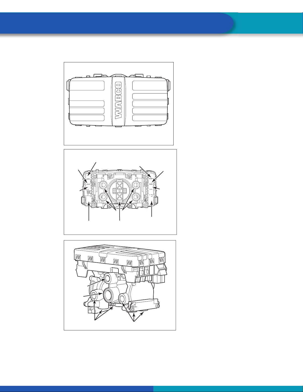
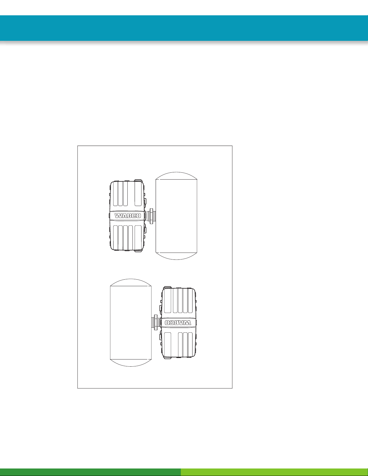
1. Before beginning the installation procedure, inspect the ECU/dual modulator valve assembly for
damage that may have occurred during shipping or storage.
Look for damaged or broken connectors.
Do not install a damaged ECU/dual modulator valve assembly. Notify your supervisor, or contact
WABCO if there is any apparent damage.
2. Have the following installation material available.
WABCO Components:
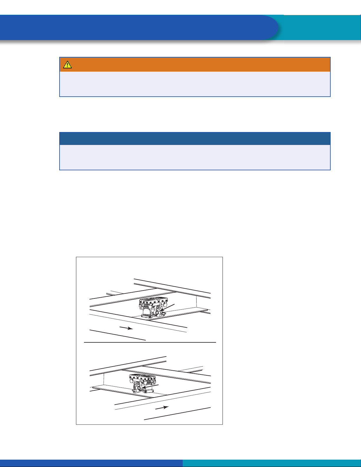
ECU/dual modulator valve assembly
ABS relay valve and relay valve extension cable (3M system only)
Power cable or power/diagnostic cable
Sensor extension cables (two pieces for 2S systems, four pieces for 4S systems)
ABS sensors (two or four) for non-ABS prepped axles
ABS Indicator Label (TP-95172)
Non-WABCO Components:
5/8-inch O.D. nylon tubing for supply (frame mount)
Pipe plug (3/4-inch NPT)
Schedule 80 hex pipe nipple (3/4-inch NPT) for air tank mounts or two Grade 8 bolts (3/8-inch)
and prevailing torque nuts for frame mounts
ABS sensor clip lubricant (the following are approved by WABCO):
•Mobilith SHC-220 (Mobil)
•TEK 662 (Roy Dean Products)
•Staburags NBU 30 PTM (Kluber Lubrication)
•Valvoline EP 633
SAE-standard, DOT-approved sealing paste
ABS indication lamp (to ensure correct lamp operation, use an incandescent-type DOT-approved
lamp, or an LED with integral load resistor)
All WABCO component part number information can be found in Appendix IV.
End of line testing must be done after all installations. WABCO recommends using TOOLBOX PLUS™
Software to perform this testing. If you do not have TOOLBOX PLUS™ Software, this bulletin also includes
instructions for testing without the software. The TOOLBOX PLUS™ Software can be purchased and
downloaded from www.wabco-snapon.com.