Gazer VAG MIB User manual

Compatible with Audi vehicles with MMI Navigation Plus based on MIB
Bentley vehicles with MIB with 8“ monitor
Lamborghini vehicles with MIB with monitor in instrument
Porsche vehicles with PCM 4.0
Seat vehicles with Media System Plus - MIB High/Standard
Skoda vehicles with MIB STD2 PQ/+NAV, Amundsen and Bolero
VW vehicles with MIB/MIB2/MQB High/Discovery Pro and
Standard/Composition Media
Product features
Video-inserter for factory-infotainment monitors
CVBS Video-Input for after-market Video sources (e.g. DVD-Player, DVB-T Tuner, …)
Automatic switching to rear-view camera input on engagement of the reverse gear
Manual switching to front camera by keypad or factory button
Activatable parking guide lines for rear-view camera (vehicle specific restrictions
possible)
Video-in-motion (ONLY for connected video-sources)
Compatible with factory rear-view camera
AV-inputs PAL/NTSC compatible
VAG MIB / MIB-2
Camera Video interface
Video-inserter for rear view camera and two more video inputs
Back camera CVBS Input
Art. 300 309

Page2
Contents
1. Prior to installation
1.1. Delivery contents
1.2. Checking the compatibility of vehicle and accessories
1.3. Boxes and connectors
1.3.1. Video-Interface
1.4. Settings of the 8 Dip switches (black)
1.4.1.1. Enabling the interface’s video inputs (dip 2-3)
1.4.1.2. Vehicle specific settings (Dip 4)
1.4.1.3. Rear-view camera setting (dip 5)
1.4.1.4. Monitor selection (Dip 6-8)
1.5. Settings of the 4 Dip switches (CAN function –red)
2. Installation
2.1. Place of installation
2.2. Connection schema
2.3. Connection to the vehicle’s head unit
2.4. Connection and power supply for the video interface
2.5. Connecting of video-sources
2.5.1. Audio insertion
2.5.2. ……After-market rear-view camera
2.5.2.1. Case 1: CAN-box receives the reverse gear signal
2.5.2.2. Case 2: CAN-box does not receive the reverse gear signal
2.6. Connecting video-interface and keypad
2.7. Picture settings and guide lines
3. Interface operation
3.1. By factory infotainment button
3.2. By keypad
4. Specifications

Page3
Legal Information
By law, watching moving pictures while driving is prohibited, the driver must not be
distracted. We do not accept any liability for material damage or personal injury resulting,
directly or indirectly, from installation or operation of this product. Apart from using this
product in an unmoved vehicle, it should only be used to display fixed menus or rear-view-
camera video when the vehicle is moving (for example the MP3 menu for DVD upgrades).
Changes/updates of the vehicle’s software can cause malfunctions of the interface. Up to
one year after purchase we offer free software-updates for our interfaces. To receive a free
update, the interface has to be sent in at own cost. Wages for de-and reinstallation and
other expenditures involved with the software-updates will not be refunded.
1. Prior to installation
Read the manual prior to installation. Technical knowledge is necessary for installation. The
place of installation must be free of moisture and away from heat sources.
1.1. Delivery contents
Take down the serial number of the interface and store this manual for support
purposes: ____________________

Page4
Requirements
Brand
Compatible vehicles
Compatible systems
Audi
A3 (8V) since 05/2012-, A4 (8W)
since 08/2015-, A5 (8T) since
07/2016-, A6 (4G) since 09/2014-,
A7 (4G) since 05/2014-, Q2 (GA)
since 09/2016-, Q5 since 2017-, Q7
(4M) since 03/2015-
MMI Navigation Plus with MMI
Touch 7", 8" or 8.3" - MIB/MIB II
Main-Unit
A3 (8V) since 05/2012-, A4 (8W)
since 08/2015-, A5 (8T) since
07/2016-, Q2 (GA) since 09/2016-,
Q5 from 2017-, Q7 (4M) since
03/2015-
MMI Navigation 7" - MIB Std
Nav/MIB Std Plus
MMI Radio Plus 5.8" or 7" - MIB
Entry Plus/MIB Std
R8 (4S) since 05/2015-, TT (8S) since
07/2014-
MMI Navigation Plus - MIB II
Main-Unit with monitor in
instrument
Bentley
Bentayga
MIB with 8" monitor
Lamborghini
Huracan 2016-
MIB with monitor in instrument
Porsche
911 (991.2 face-lift) from 12/2015-,
Cayenne, Macan and other vehicles
with
PCM 4.0
Seat
Ateca, Leon3 (5F) from 2013,
Toledo
Media System Plus - MIB
High/Standard
Skoda
Fabia3 (NJ) from 11/2014, Octavia3
(A7) and other vehicles with
MIB High/Columbus und
Standard/Bolero/Amundsen -
5.8inch, 6.5inch or 8inch
monitor.
NOT 2018 9.2inch
VW
Crafter about 2015-2016
Crafter 2017-, Golf7, Passat 2016,
Polo5 (6C) and other vehicles with
MIB/MIB2/MQB High/Discovery
Pro und Standard/Composition
Media - 5.8inch, 6.5inch, 7inch
or 8inch monitor.
NOT 2018 9.2inch.
Limitations
Video only The interface inserts ONLY video signals into the infotainment.
For inserting Audio signals either the possibly existing factory
audio-AUX-input or a FM-modulator can be used.
Factory rear-view camera Automatically switching-back from inserted video to factory
rear-view camera is only possible while the reverse gear is
engaged. To delay the switch-back an additional electronic part
is required.
1.2. Checking the compatibility of vehicle and accessories

Page5
1.3. Boxes and connectors
1.3.1. Video Interface
The video-interface converts the connected after-market sources video signals into a LVDS
signal which is inserted in the factory monitor using separate trigger options. Further it reads
the vehicle’s digital signals out of the vehicle’s CAN-bus and converts them for the video
interface.
1.4. Settings of the 8 Dip switches (black)
Some settings must be selected by the dip-switches on the
video interface. Dip position down is ON and position up is OFF.
See the following chapters for detailed information.
Dip
Function
ON (down)
OFF (up)
1
No function
set to OFF
2
CVBS Video 1-input
enabled
disabled
3
CVBS Video 2-input
enabled
disabled
4
Vehicle specific
settings
For Audi TT vehicles
all other vehicles
5
Rear-view cam type
after-market
factory or none
6
Monitor
adjustment
Try all 6 possible combinations of Dips 6, 7 and 8 to
receive the best picture (quality and size) or see chapter
“Monitor adjustment (Dip 6-8)”
7
8

Page6
1.4.1.1. Enabling the interface’s video inputs (dip 2-3)
Only the enabled video inputs can be accessed by switching through the interface’s video
sources. It is recommended to enable only the required inputs. So the disabled inputs will be
skipped while switching through the video interfaces inputs.
1.4.1.2. Vehicle specific settings (Dip 4)
Set Dip switch 4 to ON for Audi TT vehicles. For all other vehicles it has to be set to OFF.
1.4.1.3. Rear-view camera setting (dip 5)
If set to OFF, the interface switches to factory LVDS picture while the reverse gear is engaged
to display factory rear-view camera or factory optical park system picture.
If set to ON, the interface switches to its rear-view camera input while the reverse gear is
engaged.
1.4.1.4. Monitor selection (Dip 6-8)
Dips 6-8 customize the monitor-specific video settings which sometimes even vary within
head units of the same version, caused by different monitor specifications. It is necessary to
try all possible combinations while a working video source is connected to the chosen input
of the interface. One of the six combinations will show the best picture size and quality
(some may give no picture). It is possible to first hot plug through the dip combinations. If
there is no change of picture visible after trying all 6 options, retry and disconnect the 10pin
plug of the Quadlock connector between every change of the dip setting.
Empirical value:
Vehicle
Monitor
Dip 4
Dip 6
Dip 7
Dip 8
VW Golf7
8“
OFF
OFF
OFF
OFF
5.8“
OFF
OFF
OFF
ON
Audi A3 (8V)
7“
OFF
OFF
ON
OFF
5.8“
OFF
OFF
ON
ON
Audi A4 (8W), A5 (8T)
8.3“
OFF
ON
OFF
OFF
7“
OFF
OFF
OFF
OFF
Audi A6/A7 (4G)
8“
OFF
OFF
ON
ON
Audi Q7 (4M) Touch
8.3“
OFF
ON
ON
OFF
Audi Q7 (4M) MMI
7“
OFF
OFF
OFF
OFF
Porsche
OFF
OFF
OFF
OFF
VW Touran
OFF
OFF
OFF
OFF
Audi TT (8S)
ON
OFF
OFF
OFF

Page7
1.5. Settings of the 4 Dip switches (CAN functions –red)
All 4 dip-switches of the CAN-box have no function for normal use
except Porsche vehicles with PCM 4.0 and must be set to OFF.
Dip position down is ON and position up is OFF.
Vehicle/Navigation
Dip 1
Dip 2
Dip 3
Dip 4
After each Dip-switch-change a power-reset of the Can-box has to be performed!
2. Installation
To install the interface, first switch off the ignition and disconnect the vehicle’s battery.
Please read the owner`s manual of the car, regarding the battery`s disconnection! If
required, enable the car`s Sleep-mode (hibernation mode)
In case the sleep-mode does not succeed, the disconnection of the battery can be done
with a resistor lead.
If the necessary stabilized power supply for the interface is not taken directly from the
battery, the chosen connection has to be checked for being constantly stabile.
The interface needs a permanent 12V source!
2.1. Place of installation
The interface is built to be connected behind the vehicle`s head-unit.
All vehicles OFF OFF OFF OFF
Porsche with PCM 4.0 OFF ON OFF OFF

Page8
2.2. Connection schema
optional (when CAN is not used)
purple

Page9
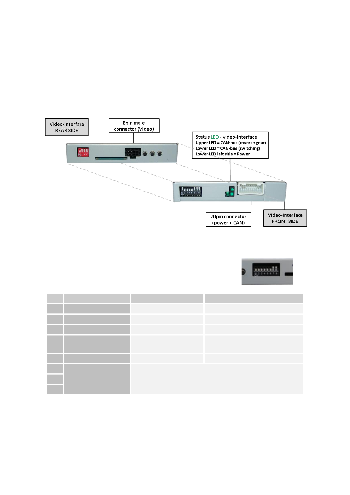
2.3. Connections to the head-unit
Remove the head-unit.
Connect the female 8pin connector of the 4pin HSD LVDS
cable to the video-interface’s male 8pin connector.
Disconnect the female 4pin HSD LVDS connector of the vehicle
harness from the rear of the head-unit and connect
it to the male 4pin HSD LVDS connector of the 8pin HSD LVDS cable.
Note: If required, the marked lug of the
female 4pin HSD LVDS connector has to be
cut off! Further, the colour of the female
4pin HSD LVDS connector may vary between
pink and grey, depending on the installed monitor.
Connect female 4pin connector of the 8pin HSD LVDS interface cable to the male 4pin
HSD LVDS connector of the head-unit (colours may vary!).
Remove the female Quadlock connector of the
vehicle harness from the rear of the
head-unit and connect the previously
clipped out white female 12pin
connector (see graphic) to the male
12pin connector of the PNP harness.
Clip in the female 12pin connector of the PNP harness in the previously become free
position of the female Quadlock connector before finishing the Quadlock
reconnection at the rear of the head-unit

Page10
2.4. Connection and power supply for the video interface
Connect the interface cable’s female 20pin connector to the 20pin connector of the
interface and connect the interfacecable’s male 10pin connector to the female 10pin
connector of the PNP harness
Connect the single, yellow wire“BATT” of the PNP harness to +12V permanent and
stabile power supply.
Connect the single, black wire “GND” of the PNP harness to the vehicle’s negative
ground.
In case of a missing CAN communication between the vehicle and the interface, the
additionately to a stabile +12V accessory power supply.
optional (when CAN is not used)
single, purple wire of the 20pin interface cable has to be connected
purple

Page11
2.5. Connecting video sources
It is possible to connect an after-market rear-view camera, an after-market front camera and
an AV source to the video-interface.
Before a final installation of the peripheral devices, we recommend a test-run to ensure
the compatibility of vehicle and interface. Due to changes in the production of the vehicle
manufacturer there’s always a possibility of incompatibility.
Note: The interface cable’s grey coloured IR cable and the audio switch cable are out of
function and should be isolated.
Connect the female 20pin connector of the interface cable to the male 20pin
connector of the video-interface.
Connect the video RCA of the Front camera to the female RCA connector“Video IN1”
of the 20pin interface cable.
Connect the video RCA of the Rear-view camera to the female RCA connector
“camera IN” of the 20pin interface cable (refer also to chapter“Video signal
connection of the rear-view camera”)
Connect the video RCA of the AV source to the female RCA connector”Video IN 2” of
the 20pin interface cable.
optional (when CAN is not used)

Page12
2.5.1. Audio-insertion
This interface is only able to insert video signals into the factory infotainment. If an AV-
source is connected, the audio insertion has to be done by the factory audio AUX input or an
FM-modulator. The inserted video-signal can be activated simultaneously to each audio-
mode of the factory infotainment.
2.5.2. After-market rear-view camera
Some vehicles have a different reverse gear code on the CAN-bus which the video-interface
is not compatible with. In this case there are two different ways of installation. If the video-
interface is able to detect an enabled vehicle’s reverse gear, the green wire of the 6pin to
12pin cable should carry +12V while the reverse gear is engaged.
Note: Do not forget to set video interface’s dip5 to ON before testing.
2.5.2.1. Case 1: CAN-box receives the reverse gear signal
If the interface delivers +12V on the green output wire of the20pin interface cable while
reverse gear is engaged, the video interface will automatically switch to the rear-view
camera input “Camera IN” while the reverse gear is engaged.
Additionally, the +12V power supply for the rear-view camera can be
taken from the red ACC-out wire of the interface connection cable.

Page13
2.5.2.2. Case 2: CAN-box does not receive the reverse gear signal
If the video interface does not deliver +12V on the green wire of the20pin cable when
reverse gear is engaged (not all vehicles are compatible), an external switching signal from
the reverse gear light is required. As the reverse gear light’s power supply isn’t voltage-
Disconnect the green cable’s preconnected male- and female connectors of the 20pin
cable and connect the green input cable “Reverse-IN” to the output connector (87) of
the relay.
Note: Not least to avoid short circuits, the best solution should be, to crimp a male
4mm connector to the relay’s output cable and connect it to the green cable’s female
4mm connector. The output-cable “Reverse-OUT” remains disconnected as it’s out of
function.
Connect the Reverse light’s power-cable to coil (85) and the vehicle’s ground to coil
(86) of the relay.
Connect the output connector (87) of the relay to the rear-view camera’s power-
cable, like you did it to the green “Reverse-IN” cable before.
Connect permanent power / 12V to the relay’s input connector (30).
is required. The diagram below shows the connection type of the relay.
stable all the time, an ordinary open relay

Page14
2.6. Connecting video-interface and keypad
Connect the female 4pin connector of the keypad to the male 4pin connector of the
20pin interface cable.

Page15
2.7. Picture settings and guide lines
The picture settings are adjustable by the 3 push-buttons on the video-interface. Press the
MENU button to open the OSD settings menu or to switch to the next menu item. Press UP
and DOWN to change the selected value. The buttons are placed inside in the housing to
avoid accidental changes during or after the installation. Picture settings must be done
separately for AV1 and AV2 while the corresponding input is selected and visible on the
monitor.
Note: The OSD menu is only shown when a working video source is connected to the
selected video-input of the interface.
The following settings are available:
Contrast
Brightness
Saturation
Position H (horizontal)
Position V (vertical)
IR-AV1/2 (no function)
Guide L/R (no function)
UI-CNTRL (guide lines ON/OFF) -
adjustments:
“All ON/All OFF”-Guide lines + PDC ON/OFF
Guide on -only guide lines
PDC on -only PDC
Size H/V (picture size horizontal/vertical)
Note: If there is no communication between the CAN box and the vehicle`s CAN-bus
(several vehicles aren’t compatible), the reverse gear guide-lines can`t be shown during the
vehicle’s operation, even if they once appear after having switched the system to powerless!

Page16
3. Interface operation
3.1. By factory infotainment button
One of the factory infotainment buttons can be used to execute interface functions.
For Skoda/Volkswagen/Audi vehicles
Press MENU button to switch the video-source
For Audi A3 vehicles
Press NAVI button to switch the video-source.
For Porsche vehicles
Press NAV button to switch the video-source.
Each press will switch to the next enabled input. Inputs which are not enabled will be
skipped.
Switchover by vehicle buttons isn’t possible in all vehicles. In some vehicles the external
keypad has to be used.
3.2. By keypad
Alternatively or additionally to the factory infotainment buttons the interface’s external
keypad can be used to switch the enabled inputs.
4. Specifications
BATT/ACC range 7V - 25V
Stand-by power drain <30mA
Power 0.3A @12V
Video input 0.7V - 1V
Video input formats PAL/NTSC
RGB-video amplitude 0.7V with 75 Ohm impedance
Temperature range -40°C to +85°C
Dimensions video-box 122 x 22 x 85 mm (W x H x D)
This manual suits for next models
2
Table of contents
Other Gazer Car Video System manuals