Gazer VI700A-SYNC3 User manual

Gazer VI700A-SYNC3
Gazer VI700S-SYNC3
INSTALLATION MANUAL

1
Contents
Precautions..................................................................................................................................................2
List of compatible cars...............................................................................................................................3
Package contents.......................................................................................................................................4
Special information.....................................................................................................................................6
Car interior disassembly and connection guide for Ford Focus..........................................................9
Troubleshooting........................................................................................................................................13

2
We congratulate you on purchasing VI700X-SYNC3 multimedia interface
Please, read this manual carefully before using the product.
Precautions
1. To install and connect the product without voiding your vehicle warranty, please contact an
authorized service station.
2. The car battery must remain disconnected during the entire installation procedure.
3. To install the product, use only original components that come in the package.
4. Do not attempt to repair the product by yourself. In case of malfunctions, please contact the
authorized Gazer maintenance center.
5. Avoid hitting and damaging the product mechanically.
6. The manufacturer reserves the right to change product specifications and/or configuration without
prior notice.
7. The product exterior design as well as the number and design of components may differ from those
specified in the manual.

3
List of compatible cars
Gazer VI700A-SYNC3 and VI700S-SYNC3 is compatible with standard Ford Sync 3
systems with 8” touchscreen display.

4
Package contents
Central unit with original monitor cables
Power and CAN bus connection cables
AUX cable
Video-in cable
Audio-in/out cable
Remote mode switching button
CAN bus signal processing unit
16 Gb Gazer micro SDHC memory card
GPS antenna
Microphone

5
Remote cable with a USB port
Remote speaker
Warranty card
User manual

6
Special information
Video interface connection
For the video interface to display an image, one needs to connect it directly to the built-in screen of
the stock multimedia system.
Video interface connection options:
• Plug&Play connection to LVDS cable between the stock navigation system and the monitor;
After the video interface is connected, the navigation system is controlled using the original
touchscreen of the stock multimedia system. It can also be controlled using a USB mouse or a keyboard.
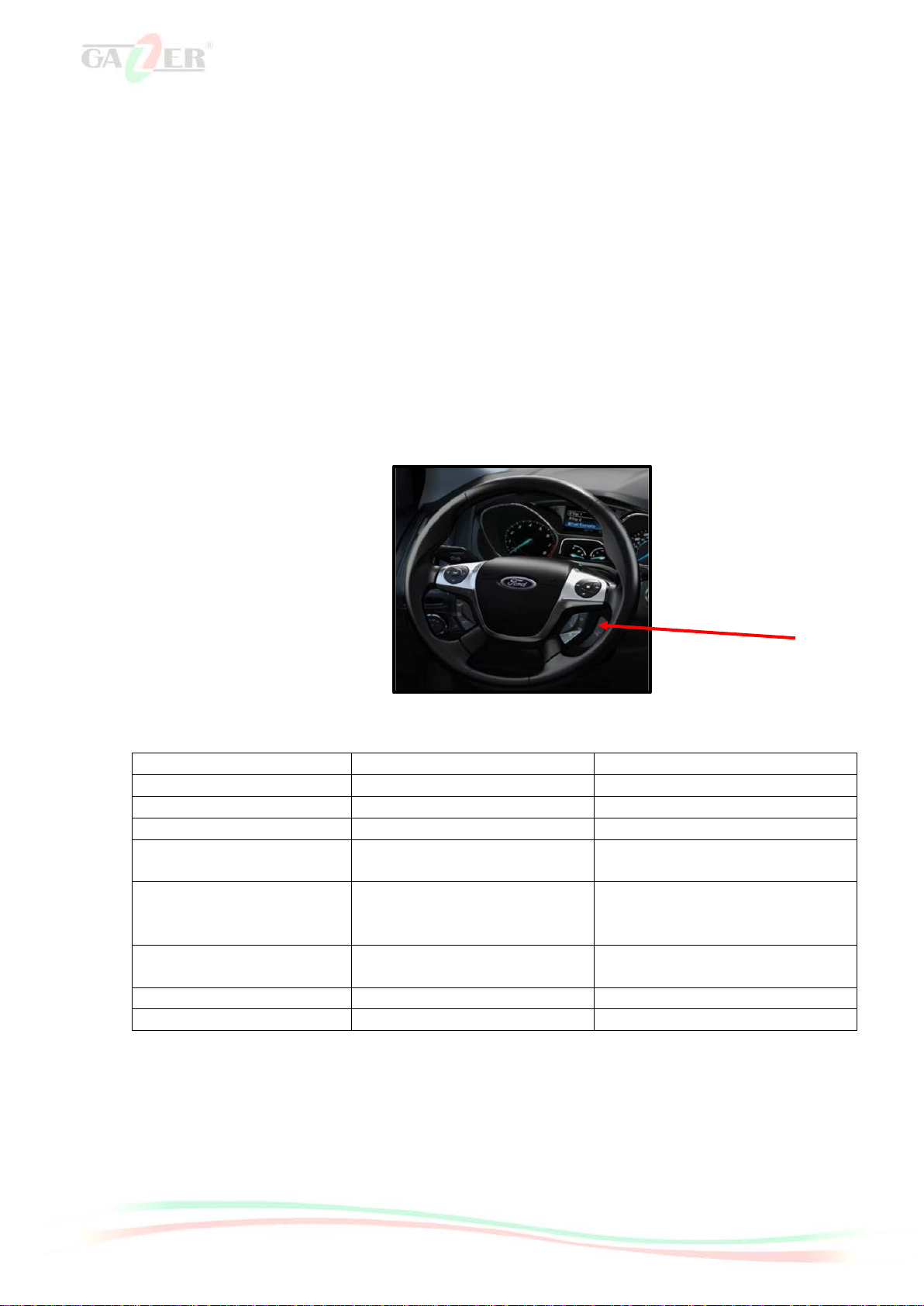
Switching between modes
To enable the video interface display mode and switch between its operating modes, you can do the
following:
•Press the remote button (comes in the package);
•Press the original Voice button on the steering wheel.
Configuring DIP switches on the video interface body
Switch No.
ON (down position)
OFF (up position)
1. RGB input
On
Off
2. AV1 input
On
Off
3. AV2 input
On
Off
4. RGB input display
resolution
800X480
480X240
5. Camera selection
If the vehicle has a rear view
camera connected to the video
interface
If the vehicle has a factory-installed
rear view camera
6. Programming or
calibration mode
Toggle down once for IR
programming
Normal use
7. Not usable
-
Always up
8. Not usable
-
Always up
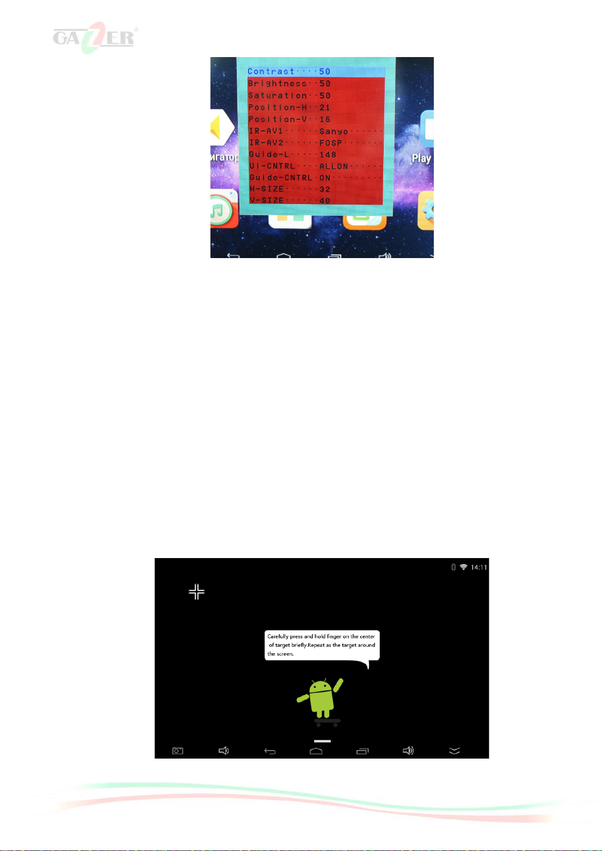
Display configuration buttons on the video interface body
There are “Menu”, “+”, and “–” buttons on the video interface lower panel that one can use to
configure how the image from the video interface will be displayed. To access the image settings menu,
press and hold “Menu" button, which will bring up the settings window. Use "Menu" button to switch
between menu items and "+", and "–" buttons to change settings.

7
•Contrast: image contrast adjustment;
•Brightness: image brightness adjustment;
•Saturation: image saturation adjustment;
•Position-H: horizontal image adjustment;
•Position-V: vertical image adjustment;
•IR-AV1/AV2: IR control settings menu for devices connected to AV1/AV2. When "None" value is
set, control buttons will not pop up when you tap the touch panel;
•Guide-L: parking guide line position adjustment;
•Ui-CNTRL: switching PDC and IPAS functions on and off;
•Guide-CNTRL: switching parking guide lines on and off;
•H-SIZE: horizontal image size adjustment;
•V-SIZE: vertical image size adjustment.
Note. Depending on the car model, the type and the number of settings may vary.
Touch panel calibration
One needs to calibrate the touch panel to ensure its correct operation. Calibration menu pops up
automatically when you switch on the video interface for the first time. To calibrate the touch panel, tap the
icons appearing on the screen as accurately as possible.Once the calibrationprocedure is complete, press
Android logo (for VI700A-SYNC3 model) or OK button (for VI700S-SYNC3 model).
Caution! If the SD card slot is empty or DIP switch No. 6 is set to "On", the touch panel calibration
procedure will have to be repeated on every startup

8
Audio connection
There are several ways to arrange audio playback from the video interface:
•Connection via Bluetooth in audio transmission mode.
To do this, connect the stock multimedia system to the video interface via Bluetooth. Then select
“Only audio” in the video interface Bluetooth settings. This is required for correct operation of Hands-Free
function when a mobile phone is connected to the stock stereo system. In this case, when the engine is
running and all equipment is fully operational, two devices (the phone and the video interface) will be
simultaneously connected to the stock stereo system. The phone will operate in Hands-Free mode, while
the video interface will playback all navigation system voice prompts as well as audio tracks.
Configuring DIP switches on the CAN bus signal processing unit
To configure the management of the use standard keys to switch the navigation mode, use the
following settings listed in the table below:
Position
Dip 1
Dip 2
Dip 3
Dip 4
All vehicles
OFF
OFF
OFF
OFF

9
Car interior disassembly and connection guide for Ford Focus
Turn the ignition and all electrical devices off.
Put the start key outside the car to avoid unintentional turning on of the ignition.
Use the wedge tool (Fig. 1) to dismantle the plastic, carefully unlatch the panel along with the air
vent deflectors as shown in figure 2.
Then switch off power and the CAN bus.
Figure 1
Figure 2

10
Release the multimedia system control unit by unscrewing 2 screws as shown in figure 3.
Figure 3
Detach the multimedia system control unit from the shaft after switching off power and the CAN bus.
Unscrew 4 fastening screws as shown in figure 4.
Detach the multimedia system display after switching off power and the CAN bus.
Figure 4
To install the interface, it is necessary to reconnect the LVDS cable of the display of the multimedia
system using the adapter from the installation kit.
Install the LVDS adapter, this requires dismantling the connector "1" in figure 5 by connecting it
using the adapter (Fig. 6). Connect LVDS out of video interface "2" to LVDS in of the monitor "3" and
LVDS out of the monitor "4" to video interface’s LVDS in "5".
To connect power and CAN bus use the adapter from the kit by connecting it to the plug "6", (Fig.
5).

11
Figure 5
Figure 6
Detach the protective rim “1” in the facing area "2".
Remove the screw “3”.
Unplug the facing “2” from the clamps in spots “4”.
Disconnect and remove the facing "2" (Fig. 7).
Figure 7
1
6
2
3
4
5

12
Install the GPS antenna in the right bottom corner of the pillar on the windshield level as shown in
figure 8.
Figure 8
Install the microphone in the ceiling module as shown below (Fig. 9).
Figure 9

13
Troubleshooting
Malfunction
Cause
Possible solution
No image/ black
screen
(manufacturer
image).
Not all plugs have been connected to the stock head
unit or monitor after installation.
Connect the remaining
plugs.
No power supplied to CAN unit (not all CAN-unit
LEDs light up).
Check CAN unit power
supply. Check CAN bus
and CAN unit
connectivity.
CAN unit is connected to CAN bus in a wrong place.
Consult the manual for
correct CAN bus
connection.
No power supplied to the video interface (not all
video interface LEDs light up).
Check whether CAN
unit is connected
properly. The output
voltage on the red wire
connected directly to the
video interface must be
+ 12V ACC
No image/ black
screen / white image
(inserted image) or
manufacturer image
is displayed
incorrectly.
No image from the video source.
Use a different monitor
to check if everything is
OK with the video
source.
No video source connected to the selected video
interface input.
Check the settings of
DIP switches 2 and 3;
see which inputs are
enabled and switch to
those inputs.
LVDS is connected in a wrong place.
Double check how
LVDS cables are
connected; consult the
manual if needed. If it
does not work when
connected to the head
unit (CD), connect it to
the monitor.
Incorrect image size
or positioning.
Inserted image is
doubled or 4
pictures are
displayed on the
monitor.
Incorrect video interface monitor settings.
Try different
combinations of video
interface DIP switches 7
and 8. Unplug the power
connector after every
change of settings to
save them. Use 3
additional buttons in the
bottom part of the video
interface.
Inserted image is
distorted, flickering
or displayed in black
and white.
Video source output is in AUTO or MULTI mode,
which causes incorrect detection of the car’s
interfaces.
Set the output video
source to PAL or NTSC.
Best of all is to use one
video standard for all
video sources.
If the error occurs only after the video source is
turned on,
Use one video standard
for all video sources.
Some interfaces can process NTSC input only.
Consult the manual for
any NTSC-related
restrictions. If only
NTSC standard is
supported, set the video
source to NTSC output.
Poor quality of
inserted image
Image settings have not been properly adjusted.
Use 3 buttons available
on the video interface to

14
Incorrect image size
setting.
configure image
parameters for the
corresponding video
input.
Incorrect image
positioning.
Camera feed
displayed in black.
Camera draws power directly from the reverse light.
Use an extra relay for a
stable signal.
Camera feed is
distorted.
Unable to adjust
camera input video
settings.
Camera input video settings can be adjusted in AV2
mode only.
Set video interface DIP
3 switch to ON (if AV2
input is not activated
yet) and connect the
camera to AV2. Then
switch to AV2 and
configure the
parameters. After that,
connect the camera to
camera input and
disconnect AV2 unless it
is used for another
video source.
Parking sensor
operation display.
PDC function is enabled in OSD interface.
In compatible vehicles,
distance data from the
factory-installed PDC
system will be displayed
on the monitor. If this
function is disabled, set
All ON in UI-CONTROL
menu item.
Chinese symbols
when the backup
camera is active.
RET or ALL function (designed for the Asian market)
is enabled in OSD menu.
Set PDC to ON in UI-
CTRL display interface
menu.
Unable to switch
between video
sources with OEM
button.
CAN bus interface does not support this function for
your car.
Use an external
keyboard or a white
CAN unit cable to switch
between video sources;
+ 12V voltage must be
supplied.
Button presses are too short.
A longer button press
(about 2.5 seconds) is
required to switch to
another video source.
The interface fails to
switch to camera
input when the
reverse gear is
engaged.
CAN bus interface does not support this function for
your car.
Cut the green wire
connecting CAN unit
with the video interface
and supply + 12V from
the reverse light. Use an
extra relay for a stable
signal.
The interface
switches between
video sources on its
own.
CAN bus interface has limited compatibility with your
vehicle.
Cut the gray wire
connecting CAN unit
with the video interface
and insulate both of its
ends. If the problem
persists, clip the white
wire as well and insulate
both of its ends.
This manual suits for next models
1
Table of contents
Other Gazer Car Video System manuals