GBC RollSeal Ultima 35 EZ load User manual

English 4
Français 10
Deutsch 16
Italiano 22
Nederlands 28
Español 34
Português 40
Svenska 46
Polski
52
Česky
58
Magyar
64
Pyccкий
70
GInstruction Manual
FManuel d’utilisation
DBedienungsanleitung
IManuale d’istruzioni
OGebruiksaanwijzing
EManual de instrucciones
PManual de Instruções
SBruksanvisning
Q
Instrukcja obsługi
o
Návod k obsluze
H
Használati útmutató
o
Руководство по
ýксплуaтaции
CZ
RUS
GBC5147 Ultima 35 EZLoad Ma-EU+ 05/11/29 12:45 PM Page 1

The only maintenance required by the operator is to periodically clean
the heat shoes. The following procedure will help keep the heat shoes
free of adhesive that has been deposited along the edge of the
laminating film.
CAUTION: THE FOLLOWING PROCEDURE IS PERFORMED
WHILE THE LAMINATOR IS HOT. USE EXTREME
CAUTION.
WARNING: Do not apply cleaning fluids or solvents to
the rollers.
WARNING: Do not attempt to laminate adhesives
marked ‘Flammable’.
Remove the film from the laminator following the procedure
outlined in the section FILM LOADING AND THREADING.
Preheat the laminator until the READY LAMP ( ) illuminates.
Clean the top and bottom heat shoes with a soft cloth.
Follow the procedure in section FILM LOADING AND THREADING,
Method Using Film Threading Card to reload the laminator.
NOTE:
Do not use metal scouring pads to clean the heat shoes!
WARNING:
Do not laminate glitter and/or metallic items. Damage to the
rollers may result.
4
3
2
1
4
G
5
General safeguards
• Use this laminator only for its intended purposes as according to the
specifications outlined in the operating instructions.
• Keep hands, long hair, loose clothing and articles such as necklaces
or ties away from the front of the pull rollers to avoid entanglement
and entrapment.
• Avoid contact with the heat shoes during operation or shortly after
the laminator has been turned off. The heat shoes can reach
temperatures in excess of 148.9ºC.
• Keep hands and fingers away from the path of the sharp film cutter
blade located at the film exit.
• Do not place the laminator on an unstable cart, stand or table. An
unstable surface may cause the laminator to fall resulting in serious
bodily injury. Avoid quick stops, excessive force and uneven floor
surfaces when moving the laminator on a cart or stand.
• Do not defeat or remove electrical and mechanical safety equipment
such as interlocks, shields and guards.
• Do not insert objects unsuitable for lamination.
• Do not expose laminator to liquids.
Installation
• Shipping damage should be brought to the immediate attention of the
delivering carrier.
• Place the laminator on a stable flat surface capable of supporting
20kgs. The surface should be at least 76.2cm high to assure
comfortable positioning during operation. All four rubber feet should
be on the supporting surface.
• Connect power cord to an appropriate power source. Avoid
connecting other equipment to the same branch circuit to which the
laminator is connected as this may cause nuisance tripping of the
circuit breaker or blown fuses.
• The laminator should be positioned to allow exiting film to drop freely
to the floor.Accumulation of laminate as it exits the laminator may
cause film to wrap around the rollers, causing a jammed condition.
• Avoid placing laminator near sources of heat or cold.Avoid locating
the laminator in the direct path of forced, heated or cooled air.
Electrical safeguards
• This laminator must be connected to a supply voltage corresponding
to the electrical rating as indicated on the serial plate located on the
rear of the machine.
• Unplug the laminator before moving it, or when it is not in use for an
extended period of time.
• Do not operate the laminator with a damaged power supply cord or
plug.
• Do not overload electrical outlets as this can result in fire or shock.
• Do not alter the attachment plug. This plug is configured for the
appropriate electrical supply.
• The unit is intended for indoor use only.
CAUTION: The receptacle must be located near the equipment
and easily accessible. Do not use an extension cord.
• Disconnect the attachment plug from the receptacle to which it is
connected and keep the power supply cord in your possession while
moving the laminator.
• Do not operate the laminator with a damaged power supply cord or
attachment plug, upon occurrence of a malfunction, or after
laminator has been damaged. Contact an authorised GBC service
representative for assistance.
Important Safety instructions
YOUR SAFETY AS WELL AS THE SAFETY OF OTHERS IS IMPORTANT TO
GBC. IN THIS INSTRUCTION MANUAL AND ON THE PRODUCT ARE
IMPORTANT SAFETY MESSAGES. READ THESE MESSAGES CAREFULLY.
ON THE PRODUCT YOU WILL FIND IMPORTANT SAFETY MESSAGES.
READ THESE MESSAGES AND INSTRUCTIONS CAREFULLY. SAVE THESE
INSTRUCTIONS FOR LATER USE.
THE FOLLOWING WARNINGS ARE FOUND ON THIS PRODUCT.
This safety message means that you could be seriously hurt or killed if
you open the product and expose yourself to hazardous voltage.
Electrical shock hazard.
Do not open. No user
serviceable parts inside.
Refer servicing to qualified
service personnel.
WARNING
THE SAFETY ALERT SYMBOL PRECEDES EACH SAFETY
MESSAGE IN THIS INSTRUCTION MANUAL.
m
WARNING: THE SAFETY ALERT SYMBOL PRECEDES
EACH SAFETY MESSAGE IN THIS INSTRUCTION
MANUAL. THIS SYMBOL INDICATES A POTENTIAL
PERSONAL SAFETY HAZARD THAT COULD HURT YOU OR
OTHERS, AS WELL AS CAUSE PRODUCT DAMAGE OR
PROPERTY DAMAGE.
m
WARNING: DO NOT ATTEMPT TO SERVICE OR REPAIR
THE LAMINATOR.
m
WARNING: DO NOT CONNECT THE LAMINATOR TO AN
ELECTRICAL SUPPLY OR ATTEMPT TO OPERATE THE
LAMINATOR UNTIL YOU HAVE COMPLETELY READ
THESE INSTRUCTIONS. MAINTAIN THESE
INSTRUCTIONS IN A CONVENIENT LOCATION FOR
FUTURE REFERENCE.
m
cm
mImportant Safeguards
WARNING: FOR YOUR PROTECTION, DO NOT CONNECT
THE LAMINATOR TO ELECTRICAL POWER OR ATTEMPT
TO OPERATE UNTIL YOU READ THESE INSTRUCTIONS
COMPLETELY. KEEP OPERATING INSTRUCTIONS IN A
CONVENIENT LOCATION FOR FUTURE REFERENCE. TO
GUARD AGAINST INJURY, THE FOLLOWING BASIC
SAFETY PRECAUTIONS MUST BE OBSERVED IN THE
SET-UP AND USE OF THE LAMINATOR.
m
WARNING: THIS IS NOT A TOY - DO NOT ALLOW CHILDREN TO OPERATE THIS LAMINATOR!
m
m
Service
Perform only the routine maintenance procedures referred to in these
instructions.
Do not attempt to service or repair the laminator.
Unplug the unit and contact an authorised GBC service representative
for any required repairs or one or more of the following has occurred:
• The power supply cord or attachment plug is damaged.
• Liquid has been spilled into the laminator.
• The laminator is malfunctioning after being mishandled.
• The laminator does not operate as described in these instructions.
m
Caring for the Ultima 35 EZload
m
m
m
m
This safety message means that you could be burned and your fingers
and hands could be trapped and crushed in the hot rollers. Clothing,
jewellery and long hair could be caught in the rollers and pull you into
them.
HOT ROLLS.
PINCH POINT.
Keep hands and
clothing away.
CAUTION
m
This safety message means that you could cut yourself if you are not
careful.
SHARP BLADE.
Keep hand and
fingers away.
CAUTION
m
453b
78a6
10
8b 9
23a1
GBC5147 Ultima 35 EZLoad Ma-EU+ 05/11/29 12:45 PM Page 3

6
Features Guide
A. POWER SWITCH: (figure 1)
Located at the back of the machine, applies power to the laminator.
The ‘ON’ position is indicated by the ‘ ’ symbol. The ‘OFF’ position
marked ‘ ’ symbol.
B. CONTROL PANEL: (figure 2)
• POWER LAMP ( ): Indicates that the laminator is plugged in and
the main power switch is in the ‘ON’ ( ) position.
• READY LAMP ( ): This will illuminate when the laminator has
reached operating temperature.
• STANDBY SWITCH ( ): Push to turn laminator on or off when
main power switch at the rear of machine is in the ‘ON’ ( )
position.
• RUN / STOP / REVERSE SWITCH ( ): Controls the
operation of the rollers. Select ‘RUN’ ( ) position to laminate.
Select ‘STOP’ ( ) position when the laminated item has passed
through the laminator. Select the ‘REVERSE’ ( ) position to
clear mis-feed, jams or wrap-ups.
• TEMPERATURE CONTROL KNOB ( ): Use to select appropriate
laminating temperature. Refer to the laminating guide on the feed
table to find the recommended setting.
C. HEAT SHIELD: (figure 3a)
Prevents inadvertent contact with the heat shoes.
D. FEED TABLE: (figure 3a)
The Feed Table is used to position items for lamination. The
laminator will operate only when the Feed Table and Feed
Table Latch are properly installed.
E. FEED TABLE LATCH: (figure 3a)
Used to lock the Feed Table into position and activate an interlock
switch. The latch is located on the right underside of the Feed
Table.The Feed Table can be removed by retracting the latch and
lifting the table upward and away from the laminator. Make sure the
feed table latch is properly locked.
F. FEED TABLE GUIDE: (figure 3a)
The Feed Table Guide aligns items to be laminated and is used to
ensure that longer items are fed into the laminator straight. The
Feed Guide may also be used to feed smaller items side by side.
Position the feed guide toward the centre of the Feed Table and
place the items to be laminated against each side of the Feed
Guide as they are being introduced into the laminator.To position
the adjustable guide, lift the guide and slide it to the desired
position.
G. HEAT SHOES: (figure 3b)
Teflon coated heat shoes melt the adhesive on the laminating film
before the nip rollers compress it.
H. IDLER BARS: (figure 3b)
The Idler Bars, located near each supply roll, are used to direct the
film to the heat shoes. The lower Idler Bar is attached to the Feed
Table to facilitate easy film loading.
I. NIP ROLLERS: (figure 3b)
The Nip Rollers are located behind the heat shoes. The nip point is
where the heated film is compressed and pulled through the
laminator.
J. PULL ROLLERS: (figure 4)
The Pull Rollers are located at the back of the laminator.They
simultaneously pull the film through the laminator and provide
tension as the film cools to provide good quality lamination.
K. REAR SLITTER: (figure 4)
Used to cut the film where it exits the rear of the laminator.
L. FUSE: (figure 4)
The Fuse is an electrical safety device, located under the main
power switch.
M. SUPPLY ROLL: (figure 5)
The Film Supply Rolls have core plugs (a, b) inserted into each end
of the rolls. The left and right plugs are of a different colour and
diameter.The colour and diameter of end plugs correspond to the
size of the holder and colour sticker located on the side plate of the
laminator.
N. AUTO SHUT-OFF:
After one hour of inactivity the laminator will shut down. To activate
the laminator, with the main power switch in the ‘ON’ ( ) position,
push the Standby Button ( ) on the control panel and wait for the
ready light ( ) to illuminate.
G
7
Film Loading and Threading
Refer to Figure 6 and follow the procedures to remove the Feed Table
and Heat Shield.
Remove the heat shield by sliding it to the left or right and lifting it
up and away from the laminator.
Slide the feed table latch to the left.
Lift the feed table upwards and away from the laminator.
CAUTION: HEAT SHOES COULD BURN YOU.
If reloading film, cut the remaining top and bottom film webs
between the supply rolls and heat shoes. Be careful not to
scratch the heat shoes.
Raise the four film holder levers and remove old rolls of film
(figure 7). Remove the old rolls and check the heat shoes for
adhesive residue. This can be easily removed by wiping with a
damp cloth. Do not use abrasive, as they will damage the Teflon
coating on the heat shoe. Change the top and bottom supply roll
at the same time.
Install new film rolls making sure that colour and diameter of end
plugs correspond to the size of the holder and colour sticker
located on the side plate of the laminator.
Close the four film holder levers.
Refer to Figure 8 or Threading Guide located on the feed table for
illustration of properly loaded film. Unwind top and bottom film
rolls allowing enough slack for threading. Drape the film from
lower supply roll over the heat shoes allowing enough slack to
re-install the feed table/idler bar. Thread film from upper roll
under the idler bar and drape over heat shoes (Figure 9).
Re-install feed table and slide feed table latch to the right.
Re-install heat shield.
Move the RUN / STOP / REVERSE SWITCH ( ) to the ‘RUN’
( ) position. Slide the threading card (provided with new rolls of
GBC laminating film) on the feed table, gently pushing the film
into the nip rollers (figure 10). The threading card should now be
guiding both rolls of film through the laminator.
Move the RUN / STOP / REVERSE SWITCH ( ) to the
‘STOP’ ( ) position when the threading card exits the rear of the
laminator.
CAUTION: SHARP BLADE.
The film cutter may be used to separate the laminated items.
Position the cutter in the middle and slide it to both sides, depress
the cutter handle while sliding the cutter across the film.
13
12
11
10
9
8
7
6
5
4
3
2
1
m
m
A
B
C
D
E
F
GBC5147 Ultima 35 EZLoad Ma-EU+ 05/11/29 12:45 PM Page 6

8
Laminating Tips
• Do not attempt to laminate abrasive or metal items such as staples
or paper clips as they will damage the heat shoes and rollers.
• Do not force items into the nip area of the rollers. An item that is not
easily drawn into the laminator is probably too thick to laminate.
• Wrinkles may result if an attempt is made to reposition an item once
the rollers have grasped it.
• Do not stop the laminator before an item has completely exited the
rear of the laminator. Even a momentary stop will cause a mark (heat
line) to appear on the laminated item.
Adhesive will be deposited on the heat shoes and rollers if:
• Only one roll of film is used. The top and bottom rolls must be used
for problem free lamination.
• One or both rolls of film are allowed to run completely off the core.
This chart is for reference only. Actual Temperature setting will vary depending on
media thickness and ink coverage.
Material
Copy Paper
Glossy Paper
Photo Paper
Electrical requirements - Refer to the serial plate located on the rear of the
laminator for the specific electrical rating applicable to the unit.
Specifications
Operating Speed
Dimensions (W x L x H)
Weight
Voltage
Current
Power
BTU/kCal
Warm-up Time
Ultima35 EZLoad
1m/min
430 x 460 x 203mm
16kg
230V ~ 50Hz
4.5A / 230VAC / 50Hz
1035W
3,534.51 BTU/hour / 890.68 kCal/hour
1 minute
9
G
Troubleshooting Guide
SYMPTOM
• POWER indicator does not illuminate when
Main power switch is in the ‘ON’ ( )
position.
• Laminated items are wrinkled.
• Laminated items are wavy.
• Laminated items are cloudy.
• Unsatisfactory adhesion to media.
• Not running
CORRECTIVE ACTION
Push standby switch on control panel.
Insert plug into appropriate receptacle.
Replace fuse.
Close lever completely.
Reduce temperature by turning temperature control
counter-clockwise.
Increase temperature by turning temperature control
clockwise.
Wait for the ready light to illuminate.
Increase temperature by turning temperature control
clockwise.
Ready light must be illuminated.
The composition or finish of the media may not be
compatible with the thermal lamination process.
Close latch
POSSIBLE CAUSE
Standby switch on control panel is not
activated.
Laminator is not connected to electrical
supply.
Fuse is blown.
Tension on top or bottom supply roll is too
loose. Film holder lever is not closed.
Excessive heat.
Insufficient heat.
Ready light is not illuminated.
Insufficient heat.
Laminated item may not be suitable for
thermal lamination.
Latch not properly locked (power to control
panel turned off)
Guarantee
Operation of this machine is guaranteed for two years from date of
purchase, subject to normal use. Within the guarantee period, GBC will
at its own discretion either repair or replace the defective machine free
of charge. Defects due to misuse or use for inappropriate purposes are
not covered under the guarantee. Proof of date of purchase will be
required. Repairs or alterations made by persons not authorised by GBC
will invalidate the guarantee. It is our aim to ensure that our products
perform to the specifications stated. This guarantee does not affect the
legal rights which consumers have under applicable national legislation
governing the sale of goods.
Register this product online at www.gbceurope.com
Operation
CAUTION: MAKE SURE HEAT SHIELD AND FEED TABLE
ARE IN THE PROPER POSITION TO OPERATE THE UNIT.
Move the Main Power switch to the ‘ON’ ( ) position (figure 1).
With the main power switch in the ‘ON’ ( ) position, the
laminator can be turned on or off using the standby switch ( )
located on the control panel. When the standby switch is activated
the red power indicator ( ) will illuminate. The laminator is now
heating.
Use the lamination guide on the feed table to select the correct
laminating temperature for the film gauge and media that you are
laminating. The guide will provide a good starting point.You may
need to adjust the temperature up or down slightly to
accommodate the finish or thickness of the media.
When the laminator reaches operating temperature, the green
ready indicator ( ) on the control panel will illuminate.
Position the item(s) to be laminated on the feed table.
Move the RUN / STOP / REVERSE SWITCH ( ) to the ‘RUN’
( ) position.
Slide the item(s) to be laminated into the nip rollers.
When the laminated item(s) exit(s) the rear of the laminator, move
the RUN / STOP / REVERSE SWITCH ( ) to the ‘STOP’
() position.
Use the Rear Slitter located at the back of the laminator to
separate the laminated item(s) from the film web.
8
7
6
5
4
3
2
1
Clearing a Film Jam (Wrap-Up)
Film jams may occur if the laminator is not positioned to allow exiting
film to drop freely to the floor.Accumulation of laminate as it exits the
laminator may cause film to wrap around the roller, causing a jammed
condition.
To clear a jam it is necessary to rotate the rollers in a reverse direction.
To clear a jam:
Immediately stop the laminator by moving the RUN / STOP /
REVERSE SWITCH ( ) to the ‘STOP’ ( ) position.
Remove the feed table and heat shield.
Cut the top and bottom film webs.
Grasp the loose ends of the web and pull straight out. Install the
feed table with the loose ends of the web on top of the table.
Move the RUN / STOP / REVERSE SWITCH ( ) to the
‘REVERSE’ ( ) position and guide the film out of the laminator.
When the film has cleared the heat shoes, move the RUN / STOP
/ REVERSE SWITCH ( ) to the ‘STOP’ ( ) position.
Thread the film per section Film Loading and Threading.
7
6
5
4
3
2
1
m
42.5mic 75mic 125mic 175mic 250mic
5 - 7 4 - 7 4 - 7 4 - 6 4 - 6
6 - 8 5 - 8 5 - 7 5 - 7 4 - 6
6 - 9 6 - 8 5 - 8 5 - 8 4 - 7
Lamination Guide
GBC5147 Ultima 35 EZLoad Ma-EU+ 05/11/29 12:45 PM Page 8

La seule opération de maintenance devant être effectuée par l’opérateur
consiste à nettoyer périodiquement les sabots chauffants. La procédure
suivante permet d’éviter tout dépôt de colle, qui a pu se déposer le long du
bord du film de plastification, sur les sabots chauffants.
ATTENTION : LA PROCÉDURE SUIVANTE EST EFFECTUÉE
ALORS QUE LA MACHINE À PLASTIFIER EST CHAUDE. SOYEZ
EXTRÊMEMENT PRUDENT.
AVERTISSEMENT : N’appliquez pas de liquide de nettoyage
ou de solvant sur les rouleaux.
AVERTISSEMENT : N’essayez pas de plastifier les adhésifs
portant la marque « Inflammable ».
Retirez le film de la machine à plastifier en suivant la procédure décrite à
la section intitulée CHARGEMENT ET INTRODUCTION DU FILM.
Préchauffez la machine à plastifier jusqu’à ce que le VOYANT VERT ( )
s’allume.
Nettoyez la partie supérieure et inférieure des sabots chauffants à l’aide
d’un chiffon doux.
Suivez la procédure de la section intitulée CHARGEMENT ET
INTRODUCTION DU FILM, méthode Utilisation du carton d’enfilage du film,
pour recharger la machine à plastifier.
REMARQUE : N’utilisez pas de tampon à récurer métallique pour nettoyer les
sabots chauffants !
AVERTISSEMENT : Ne plastifiez pas les éléments qui scintillent et/ou
métalliques. Ceci risquerait d’endommager les rouleaux.
4
3
2
1
10
F
11
Mesures de protection générales
Installation
• Tout dommage occasionné en cours d'expédition doit être immédiatement
signalé au transporteur.
• Placez la machine à plastifier sur une surface plate stable, capable de
supporter 20 kg. La surface doit mesurer au moins 76,2 cm en hauteur afin
de garantir un positionnement confortable au cours de l’opération. Les quatre
pieds en caoutchouc doivent être sur la surface de support.
• Raccordez le cordon d’alimentation à un bloc d’alimentation approprié. Évitez
de connecter tout autre équipement au circuit de branchement auquel la
machine à plastifier est raccordée car cela risque de provoquer des
nuisances au niveau du disjoncteur ou de faire sauter les fusibles.
• La machine à plastifier doit être positionnée de sorte que le film qui en sort
puisse tomber facilement sur le sol. L’accumulation de film plastifié à la
sortie de la machine à plastifier peut provoquer l’enroulement du film sur les
rouleaux, entraînant ainsi une situation de bourrage.
• Évitez de placer la machine à plastifier à proximité de sources de chaleur ou
de froid. Évitez de disposer la machine à plastifier sur le chemin direct d'une
source d'air forcé, chaud ou climatisé.
Mesures de protection
électriques
• Cette machine à plastifier doit être raccordée à une tension d’alimentation
correspondant aux caractéristiques électriques spécifiées sur la plaque du
numéro de série située à l’arrière de la machine.
• Débranchez la machine à plastifier avant de la déplacer ou en cas
d’inutilisation prolongée.
• Ne faites pas fonctionner la machine à plastifier à l’aide d’un cordon
d’alimentation ou d’une prise de courant endommagé(e).
• Ne surchargez pas les prises de courant car vous risquez de provoquer un
incendie ou un choc électrique.
• Ne modifiez pas la fiche de raccordement. Cette prise correspond à
l’alimentation électrique appropriée.
• L’appareil est destiné à une utilisation intérieure uniquement.
ATTENTION : La prise de courant doit être située à proximité de
l’équipement et facilement accessible. N’utilisez pas de rallonge
électrique.
• Déconnectez la fiche de raccordement de la prise de courant à laquelle elle
est raccordée et conservez le cordon d’alimentation en votre possession
lorsque vous déplacez la machine à plastifier.
• Ne faites pas fonctionner la machine à plastifier à l’aide d’un cordon
d’alimentation ou d’une fiche de raccordement endommagé(e), en cas de
dysfonctionnement ou si la plastifieuse est endommagée. Contactez un
représentant GBC agréé pour toute assistance.
Instructions de sécurité
importantes
GBC ATTACHE DE L'IMPORTANCE À VOTRE SÉCURITÉ AINSI QU’À CELLE
D'AUTRUI. DES MESSAGES IMPORTANTS PORTANT SUR LA SÉCURITÉ
FIGURENT DANS CE MANUEL D’INSTRUCTIONS ET SUR LE PRODUIT. LISEZ
ATTENTIVEMENT CES MESSAGES.
DES MESSAGES IMPORTANTS PORTANT SUR LA SÉCURITÉ FIGURENT SUR LE
PRODUIT. LISEZ ATTENTIVEMENT CES MESSAGES ET INSTRUCTIONS.
CONSERVEZ CES INSTRUCTIONS EN VUE D’UNE UTILISATION ULTÉRIEURE.
LES AVERTISSEMENTS SUIVANTS FIGURENT SUR CE PRODUIT.
Ce message portant sur la sécurité signifie que vous risquez de gravement
vous blesser ou de vous tuer si vous ouvrez le produit et que vous vous
exposez à une tension extrêmement dangereuse.
Risque de choc électrique.
Ne pas ouvrir. Aucune pièce
utilisable à l’intérieur. Pour
tout entretien, contactez le
personnel qualifié à cet effet.
AVERTISSEMENT
DANS CE MANUEL D’INSTRUCTIONS, LE SYMBOLE D'ALERTE DE
SÉCURITÉ PRÉCÈDE CHAQUE MESSAGE PORTANT SUR LA SÉCURITÉ.
m
AVERTISSEMENT : DANS CE MANUEL D’INSTRUCTIONS, LE
SYMBOLE D'ALERTE DE SÉCURITÉ PRÉCÈDE CHAQUE MESSAGE
PORTANT SUR LA SÉCURITÉ. CE SYMBOLE INDIQUE UN RISQUE
D’ACCIDENT PERSONNEL POTENTIEL SUSCEPTIBLE DE VOUS
BLESSER, OU AUTRUI, AINSI QUE D’ENDOMMAGEMENT DU
PRODUIT OU DU MATÉRIEL.
m
AVERTISSEMENT : N’ESSAYEZ PAS D’ENTRETENIR OU DE
RÉPARER LA MACHINE À PLASTIFIER.
m
AVERTISSEMENT : NE RACCORDEZ PAS LA MACHINE À
PLASTIFIER À UNE PRISE ÉLECTRIQUE OU N’ESSAYEZ PAS DE LA
FAIRE FONCTIONNER TANT QUE VOUS N’AVEZ PAS ENTIÈREMENT
LU CES INSTRUCTIONS. CONSERVEZ CES INSTRUCTIONS À
PORTÉE DE MAIN AFIN DE POUVOIR VOUS Y RÉFÉRER
ULTÉRIEUREMENT.
m
cm
mMesures de protection
importantes
AVERTISSEMENT : POUR VOTRE SÉCURITÉ, NE RACCORDEZ PAS LA
MACHINE À PLASTIFIER À UNE PRISE ÉLECTRIQUE OU N’ESSAYEZ
PAS DE LA FAIRE FONCTIONNER TANT QUE VOUS N’AVEZ PAS
ENTIÈREMENT LU CES INSTRUCTIONS. GARDEZ LES INSTRUCTIONS
D’UTILISATION À PORTÉE DE MAIN AFIN DE POUVOIR VOUS Y
RÉFÉRER ULTÉRIEUREMENT. AFIN DE PRÉVENIR TOUTE BLESSURE,
LES MESURES DE SÉCURITÉ DE BASE SUIVANTES DOIVENT ÊTRE
RESPECTÉES LORS DE L'INSTALLATION ET DE L’UTILISATION DE LA
MACHINE À PLASTIFIER.
m
AVERTISSEMENT : CECI N’EST PAS UN JOUET - N’AUTORISEZ PAS LES ENFANTS À FAIRE FONCTIONNER CETTE MACHINE À PLASTIFIER !
m
m
Entretien
Effectuez uniquement les procédures de maintenance habituelles auxquelles
ces instructions font référence.
N’essayez pas d’entretenir ou de réparer la machine à
plastifier.
Débranchez l’appareil et contactez un représentant GBC agréé pour toute
réparation requise ou si :
• Le cordon d’alimentation ou la fiche de raccordement est endommagé(e).
• Du liquide a été versé dans la machine à plastifier.
• La machine à plastifier ne fonctionne pas correctement après avoir été
manipulée de manière inadéquate.
• La machine à plastifier ne fonctionne pas conformément aux spécifications
décrites dans ces instructions.
m
Ultima 35 EZload : maintenance
m
m
m
m
Ce message portant sur la sécurité signifie que vous risquez de vous brûler et,
de vous coincer et écraser les doigts et mains dans les rouleaux chauffants.
Vos vêtements, bijoux et cheveux longs risquent de se prendre dans les
rouleaux et de vous y entraîner.
ROULEAUX EXTRÊMEMENT
CHAUDS.
POINT DE PRESSION.
Éloignez vos mains et vêtements.
ATTENTION
m
Ce message portant sur la sécurité signifie que vous risquez de vous couper si
vous manquez de vigilance.
LAME TRANCHANTE.
Tenez vos mains et doigts
à distance.
ATTENTION
m
• Utilisez cette machine à plastifier uniquement aux fins prévues
conformément aux spécifications indiquées dans le manuel d’utilisation.
• Éloignez vos mains, cheveux longs, vêtements amples et objets tels que les
colliers ou cravates de la partie frontale des rouleaux d'entraînement afin
d’éviter qu’ils ne s’emmêlent ou se coincent dans ces derniers.
• Évitez tout contact avec les sabots chauffants lorsque la machine à plastifier
est en marche ou peu après sa mise hors tension. Les sabots chauffants
peuvent atteindre des températures au-delà de 148,9º C.
• Tenez les mains et doigts à distance du chemin emprunté par la lame du
dispositif de coupe du film tranchante, qui se trouve à la sortie du film.
• N'installez pas la machine à plastifier sur un chariot, un stand ou une table
instable. Une surface instable peut provoquer la chute de la machine à
plastifier entraînant une blessure corporelle grave. Évitez les arrêts brusques,
toute force excessive et les sols irréguliers lorsque vous déplacez la machine
à plastifier sur un chariot ou stand.
• Ne rendez pas inopérant ou n’enlevez pas les équipements de sécurité
électriques et mécaniques tels que les systèmes de verrouillage, blindages
et protections.
• N’insérez pas d’objets non adaptés à la plastification.
• N’exposez pas la machine à plastifier aux liquides.
GBC5147 Ultima 35 EZLoad Ma-EU+ 05/11/29 12:45 PM Page 10

12
Guide des fonctions
A. INTERRUPTEUR D'ALIMENTATION : (figure 1)
Situé à l'arrière de la machine à plastifier, il permet d’alimenter celle-ci.
La position « SOUS TENSION » est indiquée par le symbole « ». La
position « HORS TENSION » est indiquée par le symbole « ».
B. PANNEAU DE COMMANDE : (figure 2)
• VOYANT D’ALIMENTATION ( ) : Indique que la machine à plastifier est
branchée et que l’interrupteur d'alimentation principal est sur la position
« SOUS TENSION » ( ).
• VOYANT PRÊT ( ) : Il s'allume lorsque la machine à plastifier a atteint
sa température de fonctionnement.
• BOUTON DE MISE EN VEILLE ( ) : Appuyez sur ce bouton pour mettre
la machine à plastifier sous ou hors tension lorsque l’interrupteur
d’alimentation principal, situé à l’arrière de la machine, est sur la position
« SOUS TENSION » ( ).
• COMMUTATEUR MARCHE / ARRÊT / ARRIÈRE ( ) : Contrôle la
mise en action des rouleaux. Sélectionnez la position « MARCHE » ( )
pour plastifier. Sélectionnez la position « ARRÊT » ( ) lorsque l’élément
plastifié a terminé son trajet dans la machine à plastifier. Sélectionnez la
position « ARRIÈRE » ( ) pour remédier une mauvaise introduction, un
bourrage ou un enroulement.
• BOUTON DE RÉGLAGE DE LA TEMPÉRATURE ( ) : Utilisez-le pour
sélectionner la température de plastification appropriée. Reportez-vous
l'abaque de à la plastification sur la table d’alimentation pour connaître
le réglage recommandé.
C. BOUCLIER THERMIQUE : (figure 3a)
Empêche tout contact par inadvertance avec les sabots chauffants.
D. TABLE D’ALIMENTATION : (figure 3a)
La table d’alimentation sert à positionner les éléments en vue de la
plastification. La machine à plastifier ne se met pas en marche tant
que la table d’alimentation et le verrou de la table d’alimentation
ne sont pas correctement installés.
E. VERROU DE LA TABLE D’ALIMENTATION : (figure 3a)
Utilisé pour enclencher la table d’alimentation, selon la position requise,
et activer le système de verrouillage. Le verrou est situé à droite sous la
table d’alimentation. La table d’alimentation peut être enlevée en retirant le
verrou et en la soulevant vers le haut de manière à l’éloigner de la
machine à plastifier.Veuillez vérifier que la table d'alimentation est bien
verrouillée.
F. GUIDE DE LA TABLE D’ALIMENTATION : (figure 3a)
Le guide de la table d’alimentation permet d’aligner les éléments à
plastifier et est utilisé afin de s’assurer que les éléments plus longs sont
introduits de manière rectiligne dans la machine à plastifier. Le guide peut
être également utilisé pour introduire des éléments de plus petite taille
côte à côte. Positionnez le guide au centre de la table d’alimentation et
placez les éléments à plastifier sur chaque côté de celui-ci lors de leur
introduction dans la machine à plastifier. Pour positionner le guide réglable,
soulevez-le et faites-le coulisser vers la position voulue.
G. SABOTS CHAUFFANTS : (figure 3b)
Les sabots chauffants revêtus de téflon font fondre la colle sur le film de
plastification avant que les rouleaux de pression ne les compressent.
H. BARRES DE SUPPORT : (figure 3b)
Les barres de support, situées à proximité de chaque rouleau de film, sont
utilisées pour acheminer le film vers les sabots chauffants. La barre de
support inférieure est fixée à la table d’alimentation afin de faciliter le
chargement du film.
I. ROULEAUX DE PRESSION : (figure 3b)
Les rouleaux de pression sont situés derrière les sabots chauffants. Le est
situé au point où le film chauffé est compressé et entraîné dans la
machine à plastifier.
J. ROULEAUX D'ENTRAÎNEMENT : (figure 4)
Les rouleaux d'entraînement sont situés à l’arrière de la machine à
plastifier.
Ils entraînent simultanément le film dans la machine à plastifier et le
tendent lorsque celui-ci se refroidit afin d’obtenir
une plastification de bonne qualité.
K. DISPOSITIF DE COUPE ARRIÈRE : (figure 4)
Utilisé pour couper le film à sa sortie, à l’arrière de la machine à plastifier.
L. FUSIBLE : (figure 4)
Le fusible est un dispositif de sécurité électrique, situé sous l'interrupteur
d’alimentation principal.
M. ROULEAU DE FILM : (figure 5)
Les rouleaux de film sont dotés
(a, b)
, d'obturateurs insérés à chacune de
leur extrémité. La couleur et le diamètre des obturateurs de gauche et de
droite diffèrent. La couleur et le diamètre des obturateurs situées aux
extrémités correspondent à la taille du support et à l’étiquette de couleur
figurant sur la plaque latérale de la machine à plastifier.
N. ARRÊT AUTOMATIQUE :
La machine à plastifier s’éteint au bout d’une heure d’inactivité. Pour
activer la machine à plastifier, lorsque l'interrupteur d’alimentation principal
est sur la position « SOUS TENSION » ( ), appuyez sur le bouton de mise
en veille ( ) situé sur le panneau de commande et attendez que le
voyant prêt ( ) s’allume.
F
13
Chargement et introduction du film
Reportez-vous à la Figure 6 et suivez les procédures pour retirer la table
d’alimentation et le bouclier thermique.
Retirez le bouclier thermique en le faisant coulisser vers la gauche ou
vers la droite, puis en le soulevant vers le haut de manière à l’éloigner de
la machine à plastifier.
Faites coulisser le verrou de la table d’alimentation vers la gauche.
Soulevez la table d’alimentation vers le haut de manière à l’éloigner de
la machine à plastifier.
ATTENTION : VOUS RISQUEZ DE VOUS BRÛLER AU CONTACT
DES SABOTS CHAUFFANTS.
Si vous rechargez le film, coupez les feuilles de film continu supérieures
et inférieures restantes qui se trouvent entre les rouleaux de film et les
sabots chauffants. Veillez à ne pas érafler les sabots chauffants.
Levez les quatre leviers de support pour film et retirez les anciens
rouleaux de film (figure 7). Retirez les anciens rouleaux et assurez-vous
que les sabots chauffants sont exempts de tout résidu de colle. Vous
pouvez aisément les enlever à l’aide d’un chiffon humide. N’utilisez pas
d’abrasif car il endommagerait le revêtement en téflon présent sur le
sabot chauffant. Changez le rouleau de film supérieur et inférieur au
même moment.
Installez les nouveaux rouleaux de film en veillant à ce que la couleur
et le diamètre des obturateurs situées aux extrémités correspondent à la
taille du support et à l’étiquette de couleur figurant sur la plaque latérale
de la machine à plastifier.
Rabaissez les quatre leviers de support de film.
Reportez-vous à la Figure 8 ou à l'abaque de plastification sur la table
d’alimentation pour obtenir une illustration d’un film correctement
chargé. Débobinez les rouleaux de film supérieurs et inférieurs en
laissant suffisamment de mou pour l’introduction. Drapez le film du
rouleau de film inférieur par dessus les chauffants en laissant
suffisamment de mou pour réinstaller la table d’alimentation/barre de
support. Introduisez le film du rouleau supérieur sous la barre de
support et drapez-le par dessus les chauffants (Figure 9).
Réinstallez la table d’alimentation et faites coulisser le verrou de la table
d’alimentation vers la droite.
Réinstallez le bouclier thermique.
Positionnez le commutateur MARCHE / ARRÊT / ARRIÈRE ( )
sur « MARCHE » ( ). Faites coulisser le carton d'introduction (livré
avec de nouveaux rouleaux de film de plastification GBC) sur la table
d’alimentation, en poussant doucement le film dans les rouleaux
de pression (figure 10). Le carton d'introduction doit désormais guider les
deux rouleaux de film dans la machine à plastifier.
Positionnez le commutateur MARCHE / ARRÊT / ARRIÈRE ( )
sur « ARRÊT » ( ) à la sortie du carton d'introduction, à l’arrière de la
machine à plastifier.
ATTENTION : LAME TRANCHANTE.
Le dispositif de coupe du film peut être utilisé pour séparer les éléments
plastifiés. Positionnez le dispositif de coupe au milieu et faites-le
coulisser vers les deux côtés, abaissez sa poignée tout en le faisant
coulisser sur le film.
13
12
11
10
9
8
7
6
5
4
3
2
1
m
m
A
B
C
D
E
F
GBC5147 Ultima 35 EZLoad Ma-EU+ 05/11/29 12:45 PM Page 12

14
Conseils pour plastifier
• N’essayez pas de plastifier des éléments abrasifs ou métalliques tels que les
agrafes ou les trombones car ils endommageraient les sabots chauffants et
les rouleaux.
• N’essayez pas d’introduire en force des éléments dans la zone de pression
des rouleaux. Tout élément qui n’est pas aisément introduit dans la machine
à plastifier est probablement trop épais pour être plastifié.
• Des plis peuvent apparaître si une tentative de repositionnement d’un
élément est effectuée une fois qu’il a été saisi par les rouleaux.
• N’arrêtez pas la machine à plastifier tant qu’un élément n’est pas
entièrement sortie de la machine à plastifier, à l’arrière de celle-ci. Même en
cas d’arrêt provisoire, une marque (ligne thermique) apparaîtra sur l’élément
plastifié.
De la colle se déposera sur les sabots chauffants et les
rouleaux si :
• Un seul rouleau de film est utilisé. Les rouleaux supérieurs et inférieurs
doivent être utilisés en vue d’une plastification sans problème.
• Un ou les deux rouleaux de film peuvent se dérouler entièrement.
Ce tableau n’est fourni qu’à titre indicatif. Le réglage de température réelle varie selon
l’épaisseur des supports et la couverture d’encre.
Matériau
Papier copieur
Papier glacé
Papier photo
Installations électriques - Reportez-vous à la plaque du numéro de série située à l’arrière de
la machine à plastifier pour connaître les caractéristiques électriques spécifiques qui
s’appliquent à l’appareil.
Caractéristiques techniques
Vitesse de plastification
Dimensions (P x L x H)
Poids
Alimentation
Courant
Puissance
BTU / kCal
Temps de préchauffage
Ultima35 EZLoad
1 m / min
430 x 460 x 203 mm
16 kg
230V ~ 50 Hz
4,5 A / 230 VAC / 50 Hz
1035 W
3 534,51 BTU/heure / 890,68 kCal/heure
1 minute
15
F
Guide de dépannage
SYMPTÔME
• Le voyant d’ALIMENTATION ne s’allume
pas lorsque le commutateur d’alimentation
principal est sur la position « SOUS TENSION »
().
• Les éléments plastifiés ont des plis.
• Les éléments plastifiés sont gondolés.
• Les éléments plastifiés sont nuageux.
• Adhésion non satisfaisante aux supports.
• Ne fonctionne pas
ACTION CORRECTIVE
Appuyez sur le bouton de mise en veille situé sur le
panneau de commande.
Insérez la fiche d’alimentation dans la prise de courant
appropriée.
Remplacez le fusible.
Rabaissez entièrement le levier.
Réduisez la température en tournant le bouton de réglage
de la température dans le sens inverse des aiguilles d’une
montre.
Augmentez la température en tournant le bouton de réglage
de la température dans le sens des aiguilles d’une montre.
Attendez que le voyant vert s’allume.
Augmentez la température en tournant le bouton de réglage
de la température dans le sens des aiguilles d’une montre.
Le voyant vert doit être allumé.
La composition ou le fini des supports n’est peut-être pas
compatible avec le processus de plastification à chaud.
Fermez le verrou
CAUSE POSSIBLE
Le bouton de mise en veille situé sur le panneau
de commande n’est pas activé.
La machine à plastifier n’est pas raccordée à un
système d’alimentation électrique.
Les fusibles ont sauté.
La tension au niveau du rouleau de distribution
supérieur ou inférieur est trop lâche. Le levier de
support pour film n’est pas rabaissé.
Chaleur excessive.
Chaleur insuffisante.
Le voyant vert n’est pas allumé.
Chaleur insuffisante.
L’élément plastifié n’est peut-être pas approprié à
la plastification à chaud.
Le verrou n'est pas bien fermé (l’alimentation est
coupée)
Garantie
Le fonctionnement de cette machine est garanti pendant deux ans à compter
de la date d’achat, sous réserve de conditions normales d’utilisation. Durant la
période de garantie, GBC choisira de réparer ou remplacer gratuitement la
machine. Les défauts dus à une mauvaise utilisation ou une utilisation non
appropriée ne sont pas couverts par cette garantie. La preuve de la date
d’achat sera demandée. Les réparations ou modifications effectuées par des
personnes non autorisées par GBC invalideront la garantie. Notre objectif est de
nous assurer que nos produits réalisent les performances déclarées. Cette
garantie n’affecte pas les droits légaux des consommateurs au titre de la
législation nationale en vigueur régissant la vente des biens de consommation.
Enregistrez ce produit en ligne sur www.gbceurope.com
Fonctionnement
ATTENTION : VEILLEZ À CE QUE LE BOUCLIER THERMIQUE ET
LA TABLE D’ALIMENTATION SOIENT CORRECTEMENT
POSITIONNÉS AVANT DE FAIRE FONCTIONNER L’APPAREIL.
Positionnez l'interrupteur d’alimentation principal sur « SOUS TENSION »
() (figure 1). Lorsque l'interrupteur d’alimentation principal est sur la
position « SOUS TENSION » ( ), la machine à plastifier peut être mise
sous ou hors tension à l’aide du bouton de mise en veille ( ) situé sur le
panneau de commande. Lorsque le bouton de mise en veille est activé, le
voyant d’alimentation « SOUS TENSION » ( ) s’allume. La machine à
plastifier est maintenant en train de chauffer.
Utilisez l'abaque de plastification qui se trouve sur la table d’alimentation
pour sélectionner la température de plastification adéquate selon
l’épaisseur de film et les supports soumis à plastification. L'abaque fait
office de point de départ, particulièrement judicieux. Vous devrez peut-être
régler la température en l’augmentant ou en la baissant légèrement de
manière à ce qu’elle soit adaptée au fini ou à l’épaisseur des supports.
Lorsque la machine à plastifier atteint sa température de fonctionnement,
le voyant « PRÊT » ( ), situé sur le panneau de commande, s’allume.
Placez le(s) élément(s) à plastifier sur la table d’alimentation.
Positionnez le commutateur MARCHE / ARRÊT / ARRIÈRE ( ) sur
« MARCHE » ( ).
Faites coulisser le(s) élément(s) à plastifier vers les rouleaux de pression.
À la sortie du ou des éléments plastifiés, à l’arrière de la machine à
plastifier, positionnez le commutateur MARCHE / ARRÊT / ARRIÈRE
( ) sur « ARRÊT » ( ).
Utilisez le dispositif de coupe arrière situé à l’arrière de la machine à
plastifier pour détacher le ou les éléments plastifiés du rouleau de film.
8
7
6
5
4
3
2
1
Dégagement d’un bourrage de
film (enroulement accidentel)
Des bourrages de film peuvent se produire si la machine à plastifier n’est pas
installée de manière à permettre au film qui en sort de tomber facilement sur
le sol. L’accumulation de film plastifié à la sortie de la machine à plastifier peut
provoquer l’enroulement du film sur le rouleau, entraînant ainsi une situation
de bourrage. Pour dégager un bourrage, il convient de faire pivoter les
rouleaux en marche arrière.
Pour dégager un bourrage :
Arrêtez immédiatement la machine à plastifier en positionnant le
commutateur MARCHE / ARRÊT / ARRIÈRE ( ) sur « ARRÊT »
().
Retirez la table d’alimentation et le bouclier thermique.
Coupez les feuilles de film continu supérieures et inférieures.
Saisissez les bords perdus des films et tirez-les de manière rectiligne.
Installez la table d’alimentation en disposant les bords perdus des films
sur sa partie supérieure.
Positionnez le commutateur MARCHE / ARRÊT / ARRIÈRE ( ) sur
« ARRIÈRE » ( ) et guidez le film pour l’extraire de la machine à
plastifier.
Lorsque le film a été extrait des sabots chauffants, positionnez le
commutateur MARCHE / ARRÊT / ARRIÈRE ( ) sur « ARRÊT »
().
Introduisez le film conformément à la section intitulée Chargement et
introduction du film.
7
6
5
4
3
2
1
m
42,5mic 75mic 125mic 175mic 250mic
5 - 7 4 - 7 4 - 7 4 - 6 4 - 6
6 - 8 5 - 8 5 - 7 5 - 7 4 - 6
6 - 9 6 - 8 5 - 8 5 - 8 4 - 7
Guide de plastification
GBC5147 Ultima 35 EZLoad Ma-EU+ 05/11/29 12:45 PM Page 14

Die einzige vom Nutzer durchzuführende Wartung besteht in der regelmäßigen
Reinigung der Heizschuhe. Das nachfolgend beschriebene Verfahren hilft dabei,
die Heizschuhe von Kleber freizuhalten, der sich entlang der Kanten der
Laminierfolie abgelagert hat.
VORSICHT: DAS NACHFOLGEND BESCHRIEBENE VERFAHREN
WIRD DURCHGEFÜHRT, WENN DAS LAMINIERGERÄT HEIß IST.
SEIEN SIE ÄUßERST VORSICHTIG.
WARNUNG: Tragen Sie keine Reinigungsflüssigkeiten oder
Lösungsmittel auf die Walzen auf.
WARNUNG: Versuchen Sie nicht, Klebstoffe mit der
Kennzeichnung ‘Brennbar’ zu laminieren.
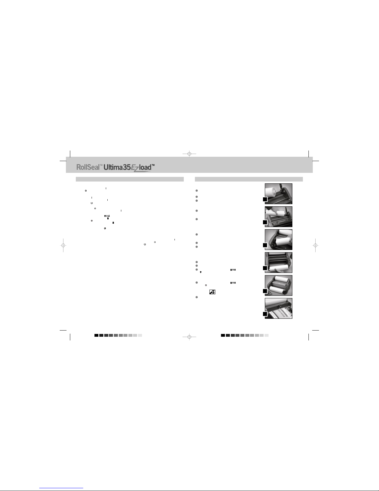
Entnehmen Sie die Folie aus dem Laminiergerät, wie im Abschnitt FOLIE
EINSETZEN UND EINFÄDELN beschrieben.
Heizen Sie das Laminiergerät vor, bis die BEREITSCHAFTANZEIGE (READY)
( ) aufleuchtet.
Reinigen Sie den oberen und unteren Heizschuh mit einem weichen Tuch.
Befolgen Sie das Verfahren im Abschnitt FOLIE EINSETZEN UND
EINFÄDELN, Einfädeln der Folie mit Kartenverfahren, um die Folie wieder
einzusetzen.
HINWEIS: Verwenden Sie keine Scheuerlappen aus Metall, um die Heizschuhe
zu reinigen!
WARNUNG: Laminieren Sie keine glitzernden- und / oder metallischen Artikel.
Dies kann zu Schäden an den Walzen führen.
4
3
2
1
16
D
17
Allgemeine Sicherheitsvorkehrungen
• Verwenden Sie das Laminiergerät ausschließlich für seinen vorgesehenen Zweck
gemäß den in der Betriebsanleitung angegebenen Spezifikationen.
• Halten Sie Hände, lange Haare, lockere Kleidung und Gegenstände wie Halsketten
oder Krawatten von der Vorderseite der Einzugswalzen fern, um zu verhindern,
dass diese sich dort verfangen.
• Vermeiden Sie eine Berührung mit den Heizschuhen beim Betrieb oder kurz nach
dem Abschalten des Laminiergeräts. Die Heizschuhe können Temperaturen von
über 148,9ºC erreichen.
• Halten Sie Hände und Finger von der Schneidbahn des scharfen
Folienschneidemessers am Folienausgang fern.
• Stellen Sie das Laminiergerät nicht auf einem unstabilen Wagen, Ständer oder
Tisch auf. Eine unstabile Auflage kann dazu führen, dass das Laminiergerät
herabstürzt und es zu schwerwiegenden Verletzungen kommt.Vermeiden Sie
Türstopper, übermäßige Gewalt und unebene Böden, wenn Sie das Laminiergerät
auf einem Wagen oder Ständer transportieren.
• Machen Sie elektrische oder mechanische Sicherheitsvorrichtungen wie Sperren,
Blenden und Schutzabdeckungen nicht unwirksam und entfernen Sie diese nicht.
• Führen Sie keine Gegenstände ein, die nicht zum Laminieren geeignet sind.
• Halten Sie Flüssigkeiten vom Laminiergerät fern.
Montage
• Der ausliefernde Spediteur ist auf etwaige Transportschäden unverzüglich
aufmerksam zu machen.
• Stellen Sie das Laminiergerät auf einer stabilen, ebenen Fläche auf, die ein
Gewicht von 20 kg tragen kann. Die Aufstellfläche muss sich mindestens
76,2 cm über Bodenhöhe befinden, damit eine bequeme Arbeitsstellung
gewährleistet ist. Das Gerät muss mit allen vier Gummifüßen auf der
Aufstellfläche aufliegen.
• Verbinden Sie das Netzkabel mit einer geeigneten Spannungsquelle.
Schließen Sie keine anderen Geräte an den Stromkreis des Laminiergeräts
an, da dies zu Störungen durch das Auslösen des Sicherungsautomaten oder
das Durchbrennen der Sicherung führen kann.
• Das Laminiergerät ist so aufzustellen, dass die austretende Folie ungehindert
auf den Boden fallen kann. Ein Stau von Folie beim Austreten aus dem
Laminiergerät kann dazu führen, dass sich die Folie um die Walzen wickelt
und das Gerät blockiert.
• Stellen Sie das Laminiergerät nicht in der Nähe von Wärme- oder
Kältequellen auf. Setzen Sie das Laminiergerät nicht direkt Heißen- oder
Kühlenluftstrom aus.
Elektrische Sicherheitsvorkehrungen
• Das Laminiergerät muss an eine Spannungsquelle angeschlossen
werden, deren elektrische Leistung der Angabe auf dem Typenschild
auf der Rückseite der Maschine entspricht.
• Trennen Sie das Laminiergerät vom Netz, bevor Sie es bewegen oder
wenn sie es für eine längere Zeit nicht benutzen.
• Betreiben Sie das Laminiergerät nicht mit einem beschädigten
Netzkabel oder Netzstecker.
• Überlasten Sie elektrische Steckdosen nicht, da dies zu Bränden
oder Stromschlägen führen kann.
• Nehmen Sie keine Veränderungen an dem Anschlussstecker vor. Der
Stecker ist für die geeignete Spannungsquelle ausgelegt.
• Das Gerät ist ausschließlich für den Gebrauch in geschlossenen
Räumen vorgesehen.
VORSICHT: Die Steckdose muss sich in der Nähe des Geräts
befinden und leicht zugänglich sein. Verwenden Sie kein
Verlängerungskabel.
• Ziehen Sie den Anschlussstecker aus der Steckdose und behalten
Sie das Netzkabel in der Hand, wenn Sie das Laminiergerät
bewegen.
• Betreiben Sie das Laminiergerät nicht mit einem beschädigten
Netzkabel oder Anschlussstecker, nach Auftreten einer Fehlfunktion
oder nach einer Beschädigung des Geräts. Setzen Sie sich zwecks
Hilfe mit einer GBC-Vertragswerkstatt in Verbindung.
Wichtige Sicherheitsanweisungen
IHRE SICHERHEIT UND DIE SICHERHEIT VON ANDEREN PERSONEN SIND FÜR GBC
SEHR WICHTIG. IN DER VORLIEGENDEN BETRIEBSANLEITUNG UND AUF DEM
GERÄT BEFINDEN SICH WICHTIGE SICHERHEITSHINWEISE. LESEN SIE DIESE
HINWEISE SORGFÄLTIG.
AUF DEM GERÄT BEFINDEN SICH WICHTIGE SICHERHEITSHINWEISE. LESEN SIE
DIESE HINWEISE UND ANWEISUNGEN SORGFÄLTIG. BEWAHREN SIE DIESE
BETRIEBSANLEITUNG ZUM SPÄTEREN GEBRAUCH AUF.
AUF DEM GERÄT BEFINDEN SICH FOLGENDE WARNUNGEN.
Dieser Sicherheitshinweis bedeutet, dass Sie ernsthaft verletzt oder getötet werden
könnten, wenn Sie das Gerät öffnen und sich einer gefährlichen elektrischen
Spannung aussetzen.
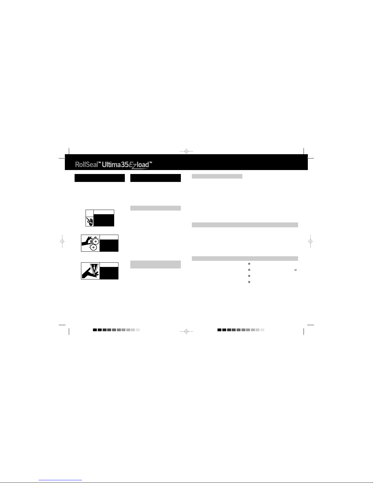
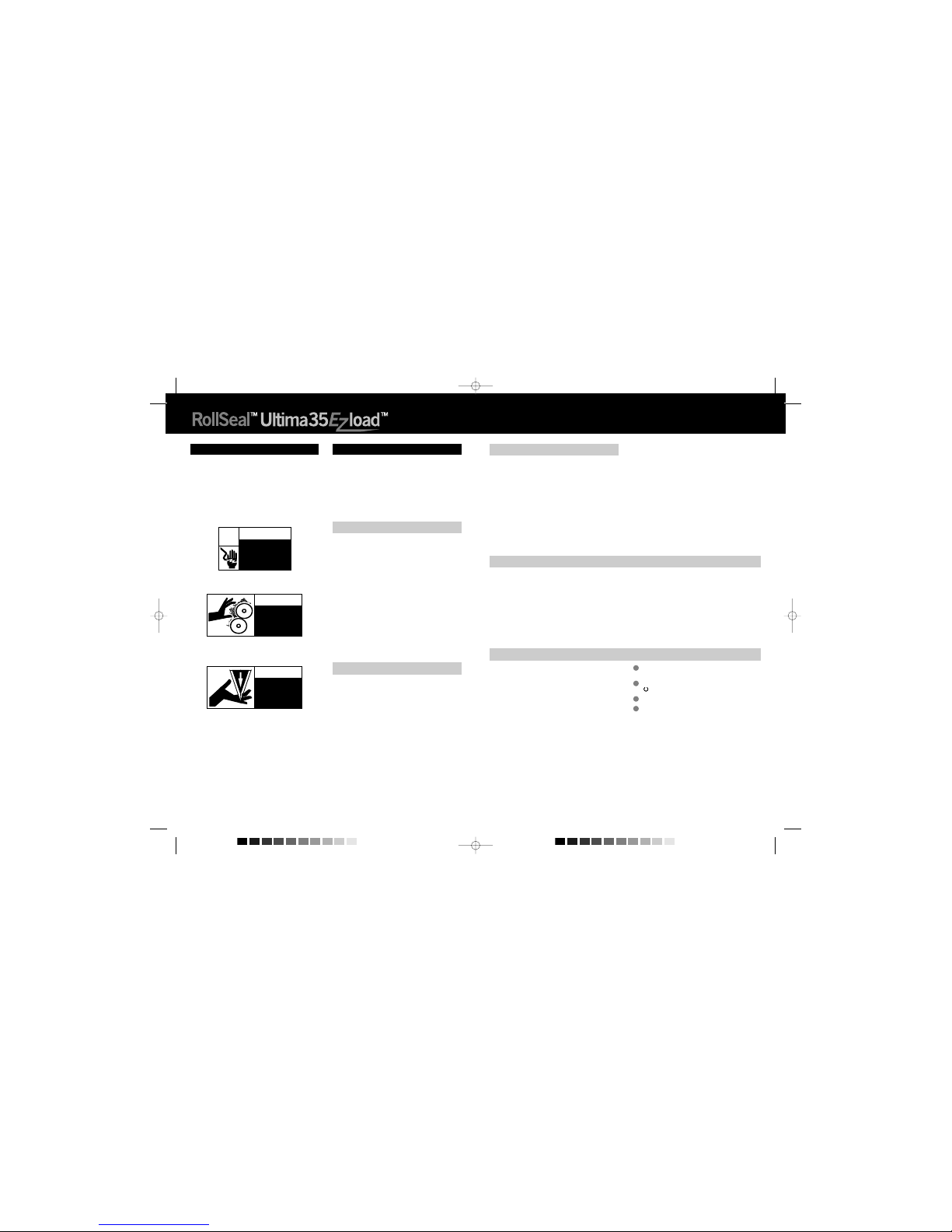
Gefahr von elektrischen Schlägen. Nicht
öffnen. Im Inneren befinden sich keine
vom Benutzer zu wartenden Teile.
Lassen Sie den Kundendienst stets
durch qualifiziertes Personal vornehmen.
WARNUNG
JEDEM SICHERHEITSHINWEIS IN DER VORLIEGENDEN
BETRIEBSANLEITUNG IST DAS WARNSYMBOL VORANGESTELLT.
m
WARNUNG: JEDEM SICHERHEITSHINWEIS IN DER VORLIEGENDEN
BETRIEBSANLEITUNG IST DAS WARNSYMBOL VORANGESTELLT.
DIESES SYMBOL WEIST AUF EIN POTENZIELLES SICHERHEITS-
RISIKO HIN, DAS ZU VERLETZUNGEN BEI IHNEN ODER ANDEREN
PERSONEN, ZU SCHÄDEN AM GERÄT ODER ZU SACHSCHÄDEN
FÜHREN KÖNNTE.
m
WARNUNG: VERSUCHEN SIE NICHT, DAS LAMINIERGERÄT
EIGENSTÄNDIG ZU WARTEN ODER ZU REPARIEREN.
m
WARNUNG: VERBINDEN SIE DAS LAMINIERGERÄT NICHT MIT
EINER ELEKTRISCHEN SPANNUNGSQUELLE UND VERSUCHEN SIE
NICHT, DAS LAMINIERGERÄT IN GANG ZU SETZEN, BEVOR SIE DIE
VORLIEGENDE BETRIEBSANLEITUNG VOLLSTÄNDIG GELESEN
HABEN. BEWAHREN SIE DIE VORLIEGENDE BETRIEBSANLEITUNG
ZUM SPÄTEREN NACHSCHLAGEN AN EINEM LEICHT
ZUGÄNGLICHEN ORT AUF.
m
cm
m
Wichtige Sicherheitsvorkehrungen
WARNUNG: VERBINDEN SIE DAS LAMINIERGERÄT ZU IHREM
EIGENEN SCHUTZ NICHT MIT EINER ELEKTRISCHEN
SPANNUNGSQUELLE UND VERSUCHEN SIE NICHT, DAS
LAMINIERGERÄT IN GANG ZU SETZEN, BEVOR SIE DIE
VORLIEGENDE BETRIEBSANLEITUNG VOLLSTÄNDIG GELESEN
HABEN. BEWAHREN SIE DIE BETRIEBSANLEITUNG ZUM SPÄTEREN
NACHSCHLAGEN AN EINEM LEICHT ZUGÄNGLICHEN ORT AUF. ZUM
SCHUTZ VOR VERLETZUNGEN SIND BEIM EINRICHTEN UND BEI
DER VERWENDUNG DES LAMINIERGERÄTS DIE FOLGENDEN
ELEMENTAREN SICHERHEITSVORKEHRUNGEN ZU BEACHTEN.
m
WARNUNG: DAS GERÄT IST KEIN SPIELZEUG - LASSEN SIE DAS GERÄT NICHT DURCH KINDER BEDIENEN!
m
m
Wartung
Führen Sie ausschließlich die in der vorliegenden Betriebsanleitung genannten
Routinewartungen durch.
Versuchen Sie nicht, das Laminiergerät eigenständig zu
warten oder zu reparieren.
Trennen Sie das Gerät in folgenden Fällen vom Netz und setzen Sie sich mit
einer GBC-Vertragswerkstatt in Verbindung:
• Netzkabel oder Anschlussstecker sind beschädigt.
• Es wurde Flüssigkeit über das Laminiergerät verschüttet.
• Das Laminiergerät weist nach falscher Bedienung Fehlfunktionen auf.
• Das Laminiergerät funktioniert nicht, wie in der vorliegenden
Betriebsanleitung beschrieben.
m
Pflege des Ultima 35 EZload
m
m
m
m
Dieser Sicherheitshinweis bedeutet, dass Sie sich Verbrennungen zuziehen und
dass sich Ihre Hände in den heißen Walzen verfangen und gequetscht werden
könnten. Kleidung, Schmuck und lange Haare könnten sich in den Walzen
verfangen und Sie hineinziehen.
HEIßE WALZEN.
QUETSCHGEFAHR.
Halten Sie Hände
und Kleidung fern.
VORSICHT
m
Dieser Sicherheitshinweis bedeutet, dass Sie sich Schnittverletzungen zuziehen
könnten, wenn Sie sich nicht vorsehen.
SCHARFES MESSER.
Halten Sie Hände
und Finger fern.
VORSICHT
m
GBC5147 Ultima 35 EZLoad Ma-EU+ 05/11/29 12:45 PM Page 16

18
Merkmale des Geräts
A. NETZSCHALTER: (Abbildung 1)
Der Netzschalter befindet sich an der Rückseite des Laminiergeräts und
schaltet die Netzspannung ein und aus. Die Stellung ‘AN’ ist durch das
Symbol ‘ ’ gekennzeichnet. Die Stellung ‘AUS’ ist durch das Symbol ‘ ’
gekennzeichnet.
B. BEDIENFELD: (Abbildung 2)
• NETZANZEIGE (POWER) ( ): Die Netzanzeige zeigt an, dass der
Netzstecker des Laminiergeräts eingesteckt ist und der Netzschalter sich
auf der Stellung ‘AN’ ( ) befindet.
• BEREITSCHAFTSANZEIGE (READY) ( ): Die Bereitschaftsanzeige
leuchtet auf, wenn das Laminiergerät Betriebstemperatur erreicht hat.
• STANDBY-TASTE ( ): Drücken Sie diese Taste, um das Laminiergerät
ein- oder auszuschalten, wenn sich der Netzschalter an der Rückseite
des Geräts auf der Stellung ‘AN’ ( ) befindet.
• SCHALTER START / STOP / ZURÜCK ( ): Dieser Schalter steuert
die Walzen.Wählen Sie ‘START’ ( ) zum Laminieren. Wählen Sie
‘STOP’ ( ), wenn der laminierte Artikel das Laminiergerät passiert hat.
Wählen Sie ‘ZURÜCK’ ( ), um Fehlzufuhr, Stau oder Aufwickeln der
Folie zu beseitigen.
• TEMPERATURREGELKNOPF ( ): Verwenden Sie den Knopf zum
Einstellen der passenden Laminiertemperatur. Die empfohlene Einstellung
entnehmen Sie bitte dem Laminierleitfaden auf dem Anlegetisch.
C. HITZESCHUTZ: (Abbildung 3a)
Der Hitzeschutz verhindert einen versehentlichen Kontakt mit den
Heizschuhen.
D. ANLAGETISCH: (Abbildung 3a)
Der Anlagetisch dient zum Ausrichten der zu laminierenden Unterlagen.
Das Laminiergerät arbeitet nur, wenn Anlagetisch und
Anlagetischriegel richtig angebracht sind.
E. ANLAGETISCHRIEGEL: (Abbildung 3a)
Der Anlagetischriegel dient dazu, den Anlegetisch in seiner Stellung zu
verriegeln und einen Sicherheitsschalter zu betätigen. Der Riegel befindet
sich auf der rechten Unterseite des Anlegetischs. Der Anlegetisch kann
entfernt werden, indem der Riegel eingezogen und der Tisch angehoben
und vom Gerät weggezogen wird. Stellen Sie sicher daß der Riegel der
Auflage geschlossen ist.
F. FÜHRUNG ANLAGETISCH: (Abbildung 3a)
Die Führung des Anlegetischs dient zum Ausrichten der zu laminierenden
Unterlagen und soll sicherstellen, dass längere Artikel gerade in das
Laminiergerät eingeführt werden. Die Führung kann auch dazu verwendet
werden, schmalere Unterlagen nebeneinander einzuführen. Platzieren
Sie die Führung in der Mitte des Anlagetischs und legen Sie die zu
laminierenden Unterlagen auf beiden Seiten der Führung an, während sie
in das Laminiergerät eingeführt werden. Heben Sie die Führung zum
Verstellen an und schieben Sie sie in die gewünschte Position.
G. HEIZSCHUHE: (Abbildung 3b)
Die teflonbeschichteten Heizschuhe schmelzen den Klebstoff auf der
Laminierfolie, bevor die Anpresswalzen die Folie pressen.
H. LEITSTANGE: (Abbildung 3b)
Leitstangen befinden sich neben jeder Folienrolle und dienen dazu,
die Folie den Heizschuhen zuzuführen. Die untere Leitstange ist am
Anlegetisch angebracht, um das Einlegen der Folie zu erleichtern.
I. ANPRESSWALZEN: (Abbildung 3b)
Die Anpresswalzen befinden sich hinter den Heizschuhen. Der
Anpresspunkt ist dort, wo die erhitzte Folie gepresst und durch das
Laminiergerät gezogen wird.
J. ZUGWALZEN: (Abbildung 4)
Die Zugwalzen befinden sich an der Rückseite des Laminiergeräts. Sie
ziehen die Folie gleichzeitig durch das Laminiergerät und spannen die
abkühlende Folie, was für Laminierergebnisse von guter Qualität sorgt.
K. HINTERE SCHNEIDEEINRICHTUNG: (Abbildung 4)
Die Schneideeinrichtung dient zum Schneiden der Folie, wo diese an der
Rückseite aus dem Laminiergerät tritt.
L. SICHERUNG: (Abbildung 4)
Die elektrische Sicherung befindet sich unter dem Netzschalter.
M. FOLIENROLLE: (Abbildung 5)
Die Folienrollen verfügen über Kernzapfen an den Rollenenden
(a, b)
.
Farbe und Durchmesser der Zapfen für die rechte und linke Seite sind
verschieden. Die Farbe und der Durchmesser der Kernzapfen entsprechen
dem Durchmesser der Haltevorrichtung und dem Farbaufkleber auf den
Seitenteilen des Laminiergeräts.
N. SELBSTABSCHALTUNG:
Nach einer Stunde ohne Aktivität schaltet sich das Laminiergerät selbst ab.
Um das Laminiergerät bei Netzschalter auf Stellung ‘AN’ ( ) zu aktivieren,
drücken Sie die Standby-Taste ( ) auf dem Bedienfeld und warten Sie,
bis die Bereitschaftsanzeige ( ) aufleuchtet.
D
19
Folie Einsetzen und Einfädeln
Beachten Sie Abbildung 6 und befolgen Sie die Verfahren zum Abnehmen von
Anlegetisch und Hitzeschutz.
Nehmen Sie den Hitzeschutz ab, indem Sie ihn nach links oder rechts
schieben und vom Laminiergerät abheben.
Schieben Sie den Riegel des Anlegetischs nach links.
Heben Sie den Anlegetisch an und nehmen Sie ihn vom Laminiergerät
ab.
VORSICHT: DIE HEIZSCHUHE KÖNNEN VERBRENNUNGEN
VERURSACHEN.
Durchschneiden Sie beim Wiedereinlegen der Folie die verbliebene obere
und untere Folienbahn zwischen Folienrollen und Heizschuhen. Achten
Sie sorgfältig darauf, die Heizschuhe nicht zu zerkratzen.
Klappen Sie die vier Folienhalterhebel nach oben und nehmen Sie die
alten Folienrollen ab (Abbildung 7). Nehmen Sie die alten Rollen ab und
prüfen Sie die Heizschuhe auf Klebstoffrückstände. Diese können mit
Hilfe eines feuchten Tuchs leicht entfernt werden. Verwenden Sie keine
Scheuermittel, da diese die Teflonbeschichtung der Heizschuhe
beschädigen. Wechseln Sie obere und untere Folienrolle gleichzeitig.
Setzen Sie neue Folienrollen ein und vergewissern Sie sich, dass die
Farbe und der Durchmesser der Kernzapfen dem Durchmesser der
Haltevorrichtung und dem Farbaufkleber auf den Seitenteilen des
Laminiergeräts entsprechen.
Schließen Sie die Folienhalterhebel.
Eine Darstellung einer korrekt eingelegten Folie entnehmen Sie bitte
Abbildung 8 oder dem Einfädel-Leitfaden auf den Anlagetisch. Wickeln
Sie genug Folie von der oberen und unteren Rolle ab, um die Folie
einfädeln zu können. Legen Sie die Folie von der unteren Rolle über die
Heizschuhe und lassen Sie genug Spiel, um Anlagetisch / Leitstange
wieder anbringen zu können. Führen Sie die Folie von der oberen
Rolle unter der Leitstange hindurch und legen Sie sie über die
Heizschuhe (Abbildung 9).
Bringen Sie den Anlagetisch wieder an und schieben Sie den Riegel des
Anlegetischs nach rechts.
Bringen Sie den Hitzeschutz wieder an.
Stellen Sie den SCHALTER START / STOP / ZURÜCK ( )
auf ‘START’ ( ). Schieben Sie die (wird mit neuen GBC-
Laminierfolienrollen mitgelieferte) Einfädelkarte auf dem Anlegetisch
entlang und schieben Sie die Folie vorsichtig in die Anpresswalzen
(Abbildung 10). Die Einfädelkarte muss nun beide Folienrollen durch das
Laminiergerät hindurchführen.
Stellen Sie den SCHALTER START / STOP / ZURÜCK ( ) auf
‘STOP’ ( ), wenn die Einfädelkarte das Laminiergerät an der Rückseite
verlässt.
VORSICHT: SCHARFES MESSER.
Zum Trennen der laminierten Objekte kann die Folienschneidevorrichtung
verwendet werden. Richten Sie die Schneidevorrichtung auf einer Seite
des Laminiergeräts aus, drücken Sie den Schneidgriff herunter und
ziehen Sie die Schneidevorrichtung über die Folie.
13
12
11
10
9
8
7
6
5
4
3
2
1
m
m
A
B
C
D
E
F
GBC5147 Ultima 35 EZLoad Ma-EU+ 05/11/29 12:45 PM Page 18

20
Laminiertipps
• Versuchen Sie nicht, scheuernde Unterlagen oder Gegenstände aus Metall
wie Heft- oder Büroklammern zu laminieren, da dadurch die Heizschuhe und
Walzen beschädigt werden.
• Führen Sie keine Medium gewaltsam in den Anpressbereich der
Anpresswalzen ein. Unterlagen, die sich vom Laminiergerät nicht leicht
einziehen lassen, sind wahrscheinlich zu dick zum Laminieren.
• Sollten Sie versuchen, einen Medium neu auszurichten, wenn die Walzen ihn
schon erfasst haben, entstehen Falten.
• Halten Sie das Laminiergerät nicht an, bevor ein Medium das Gerät an der
Rückseite vollständig verlassen hat. Selbst ein vorübergehender Stop
hinterlässt eine Spur (Hitzeabdruck) auf den laminierten Medium.
Es lagert sich Klebstoff auf den Heizschuhen und Walzen ab, wenn:
• lediglich eine Folienrolle verwendet wird. Für ein problemfreies Laminieren
müssen obere und untere Rolle verwendet werden.
• Eine oder beide Rollen laufen nicht kernzentriert.
Diese Tabelle soll nur als Hinweis dienen.Die tatsächliche Temperatureinstellung hängt ab
von der Stärke und Bedruckung des Mediums.
Material
Kopierpapier
Glanzpapier
Fotopapier
Elektrische Anforderungen - Genaue für das Gerät geltende elektrische Leistung siehe
Typenschild an der Rückseite des Laminiergeräts.
Technische Daten
Arbeitsgeschwindigkeit
Abmessungen (B x T x H)
Gewicht
Spannung
Stromaufnahme
Leistung
BTU / kCal
Aufheizzeit
Ultima35 EZLoad
1 m / Min
430 x 460 x 203 mm
16 kg
230V ~ 50 Hz
4,5 A / 230 VAC / 50 Hz
1035 W
3 534,51 BTU/Stunde / 890,68 kCal/Stunde
1 Minute
21
D
Fehlerbehebung
SYMPTOM
• Die Netzanzeige (POWER) leuchtet nicht, wenn
der Netzschalter sich auf der Stellung ‘AN’ ( )
befindet.
• Die laminierten Artikel weisen Falten auf.
• Die laminierten Artikel sind wellig.
• Die laminierten Artikel weisen Eintrübungen
auf.
• Unbefriedigende Klebewirkung auf Medium.
• Gerät arbeitet nicht
ABHILFE
Drücken Sie die Standby-Taste auf dem Bedienfeld.
Stecken Sie den Stecker in eine geeignete Steckdose.
Ersetzen Sie die Sicherung.
Folienhaltehebel ist nicht geschlossen. Schließen Sie den
Hebel vollständig.
Senken Sie die Temperatur, indem Sie die
Temperatursteuerung gegen den Uhrzeigersinn drehen.
Erhöhen Sie die Temperatur, indem Sie die
Temperatursteuerung im Uhrzeigersinn drehen.
Warten Sie, bis die Bereitschaftsanzeige aufleuchtet.
Erhöhen Sie die Temperatur, indem Sie die
Temperatursteuerung im Uhrzeigersinn drehen.
Die Bereitschaftsanzeige erleuchtet sein.
Die Zusammensetzung oder Oberfläche des Mediums ist
möglicherweise nicht für den Heißlaminationsprozess
geeignet.
Verschließ den Riegel
MÖGLICHE URSACHE
Standby-Taste auf dem Bedienfeld ist nicht
aktiviert.
Das Laminiergerät ist nicht mit dem Stromnetz
verbunden.
Die Sicherung ist durchgebrannt.
Die Spannung auf der oberen oder unteren
Folienrolle ist zu niedrig.
Zu hohe Tepperatur.
Zu niedriege Tepperatur.
Bereitschaftsanzeige leuchtet nicht.
Zu niedriege Tepperatur.
Der laminierte Artikel eignet sich möglicherweise
nicht zur Heißlamination.
Riegel ist nicht richtig geschlossen (Die
Stromversorgung schaltet sich aus)
Betrieb
VORSICHT: VERGEWISSERN SIE SICH, DASS SICH
HITZESCHUTZ UND ANLAGETISCH IN DER RICHTIGEN
POSITION FÜR DEN BETRIEB DES GERÄTS BEFINDEN.
Stellen Sie den Netzschalter auf ‘AN’ ( ) (Abbildung 1). Befindet sich
der Netzschalter auf der Stellung ‘AN’ ( ), kann das Laminiergerät mit
Hilfe der auf dem Bedienfeld befindlichen Standby-Taste ( ) an- und
ausgeschaltet werden. Wenn die Standby-Taste betätigt wird, leuchtet
die rote Netzanzeige ( ) auf. Das Laminiergerät heizt jetzt auf.
Wählen Sie mit Hilfe des Laminierleitfaden auf dem Anlagetisch die
korrekte Laminiertemperatur für die verwendete Folienstärke und das
zu laminierende Medium aus. Der Leitfaden bietet einen guten
Ausgangspunkt. Unter Umständen müssen Sie die Temperatur leicht
nach oben oder unten anpassen, um der Oberfläche oder der Dicke
des Mediums Rechnung zu tragen.
Wenn das Laminiergerät Betriebstemperatur erreicht, leuchtet die grüne
Bereitschaftsanzeige ( ) auf dem Bedienfeld auf.
Richten Sie das zu laminierenden Medium auf den Anlagetisch aus.
Stellen Sie den SCHALTER START / STOP / ZURÜCK ( ) auf
‘START’ ( ).
Schieben Sie das zu laminierenden Medium in die Anpressrollen.
Stellen Sie den SCHALTER START / STOP / ZURÜCK ( ) auf
‘STOP’ ( ), wenn das laminierte Medium das Laminiergerät an der
Rückseite verlässt..
Trennen Sie das laminierte Medium mit Hilfe der an der Rückseite des
Laminiergeräts befindlichen hinteren Schneideeinrichtung von der
Folienbahn ab.
8
7
6
5
4
3
2
1
Beseitigen von Folienstau
(Aufwicklung)
Wenn das Laminiergerät nicht so aufgestellt wird, dass die austretende Folie
ungehindert auf den Boden fallen kann, kann es zum Folienstau kommen. Ein
Stau von Folie beim Austreten aus dem Laminiergerät kann dazu führen, dass
sich die Folie um die Walze wickelt und das Gerät blockiert.
Um einen Stau zu beseitigen, müssen die Walzen in die entgegengesetzte
Richtung gedreht werden.
Beseitigen eines Staus:
Stoppen Sie das Laminiergerät sofort, indem Sie den SCHALTER START /
STOP / ZURÜCK ( ) auf ‘STOP’ ( ) stellen.
Nehmen Sie Anlagetisch und Hitzeschutz ab.
Durchtrennen Sie die obere und untere Folienbahn.
Ergreifen Sie die freien Enden der Bahnen und ziehen sie die Folie
gerade heraus. Bringen Sie den Anlegetisch mit den darauf befindlichen
freien Enden der Bahnen wider an.
Stellen Sie den SCHALTER START / STOP / ZURÜCK ( ) auf
‘ZURÜCK’ ( ) und geleiten Sie die Folie aus dem Laminiergerät
heraus.
Stellen Sie den SCHALTER START / STOP / ZURÜCK ( ) auf
‘STOP’ ( ), wenn die Folie die Heizschuhe passiert hat.
Fädeln Sie die Folie entsprechend dem Abschnitt Folie einsetzen und
einfädeln ein.
7
6
5
4
3
2
1
m
Garantie
Wir übernehmen die Garantie für die Funktionsfähigkeit dieser Maschine bei
normaler Nutzung für 2 Jahre ab Kaufdatum. Innerhalb des Garantiezeitraums
repariert oder ersetzt GBC die schadhafte Maschine kostenlos und nach
eigenem Ermessen. Mängel aufgrund von Mißbrauch oder Zweckentfremdung
fallen nicht unter die Garantie. Das Kaufdatum ist nachzuweisen. Reparaturen
oder Veränderungen, die durch nicht von GBC autorisierte Personen
durchgeführt werden, heben die Garantie auf. Wir wollen sicherstellen, dass
unsere Produkte die in den Spezifikationen angegebene Leistung erbringen.
Diese Garantie beeinträchtigt keine gesetzlichen Rechte, die Verbraucher
gemäß der jeweils geltenden nationalen Rechtsprechung bezüglich des
Verkaufs von Waren haben.
Lassen Sie dieses Gerät online unter www.gbceurope.com registrieren.
42,5mic 75mic 125mic 175mic 250mic
5 - 7 4 - 7 4 - 7 4 - 6 4 - 6
6 - 8 5 - 8 5 - 7 5 - 7 4 - 6
6 - 9 6 - 8 5 - 8 5 - 8 4 - 7
Laminierleitfaden
GBC5147 Ultima 35 EZLoad Ma-EU+ 05/11/29 12:45 PM Page 20

L'unica manutenzione richiesta all'operatore è la pulitura periodica delle piastre
di riscaldamento. La procedura descritta di seguito consente di mantenere le
piastre di riscaldamento libere dall'adesivo che si deposita lungo il bordo della
pellicola utilizzata per la plastificazione.
ATTENZIONE: LA PROCEDURA DESCRITTA DI SEGUITO DEVE
ESSERE ESEGUITA QUANDO LA PLASTIFICATRICE È CALDA.
USARE ESTREMA PRUDENZA.
AVVISO: non applicare ai rulli liquidi per la pulitura o
solventi.
AVVISO: non eseguire la plastificazione degli adesivi
contrassegnati come "infiammabili".
Rimuovere la pellicola dalla plastificatrice seguendo la procedura descritta
nella sezione CARICAMENTO E DISPOSIZIONE DELLA PELLICOLA.
Preriscaldare la plastificatrice fino a quando la SPIA "PRONTO" ( ) non
s’illumina.
Pulire le piastre di riscaldamento superiore e inferiore con un panno
soffice.
Seguire la procedura relativa al metodo di utilizzo della scheda di
disposizione della pellicola descritta nella sezione CARICAMENTO E
DISPOSIZIONE DELLA PELLICOLA per ricaricare la plastificatrice.
NOTA: per la pulitura delle piastre di riscaldamento non utilizzare tamponi per
la pulizia del metallo.
AVVISO: non eseguire la plastificazione di elementi luccicanti e/o metallici.
Questa operazione può provocare danni ai rulli.
4
3
2
1
I
23
Installazione
• Eventuali danni alla confezione devono essere immediatamente riferiti
all'addetto che ha operato la consegna.
• Posizionare la plastificatrice su una superficie livellata e stabile, in grado di
supportare il peso di 20 kg. La superficie deve essere ad almeno 76,2 cm
dal suolo per garantire un posizionamento agevole durante il funzionamento.
Sulla superficie di supporto devono essere presenti i quattro piedini in
gomma.
• Collegare il cavo d’alimentazione a una sorgente di alimentazione
appropriata. Non collegare altre apparecchiature allo stesso circuito a cui è
collegata la plastificatrice, in quanto possono verificarsi interferenze dannose
o la bruciatura dei fusibili.
• La plastificatrice deve essere posizionata in modo tale da consentire la
caduta libera della pellicola che fuoriesce dalla macchina. L'accumulo della
pellicola fuoriuscita dalla plastificatrice può provocarne l'avvolgimento intorno
ai rulli e determinare una condizione d’inceppamento.
• Non posizionare la plastificatrice accanto a fonti di calore o di freddo intenso.
Non posizionare la plastificatrice in direzione di impianti di aerazione o di
riscaldamento o raffreddamento.
AVVISO: QUESTA MACCHINA NON È UN GIOCATTOLO. EVITARE L’UTILIZZO DELLA PLASTIFICATRICE DA PARTE DEI BAMBINI.
m
Assistenza
Eseguire solo le procedure di manutenzione di routine indicate nelle presenti
istruzioni.
Non tentare di smontare o riparare la plastificatrice.
Scollegare l'unità e contattare un rappresentante dell'assistenza GBC
autorizzato per tutte le riparazioni necessarie o quando si verificano una o più
delle seguenti condizioni:
• Il cavo d’alimentazione o il connettore fornito in dotazione è danneggiato.
• All'interno della plastificatrice è penetrato del liquido.
• Si è verificato un malfunzionamento nella plastificatrice a seguito di una
manovra errata.
• La plastificatrice non funziona secondo quanto descritto nelle presenti
istruzioni.
m
Manutenzione dell’apparecchiatura Ultima 35 EZload
m
m
m
22
Precauzioni generali
Precauzioni relative ai
componenti elettrici
• Collegare la plastificatrice ad una sorgente d’alimentazione corrispondente
alla potenza elettrica indicata sulla piastra del numero di serie posizionata
sulla parte posteriore della macchina.
• Scollegare la plastificatrice prima di spostarla oppure quando non viene
utilizzata per un lungo periodo di tempo.
• Non utilizzare la plastificatrice se il cavo d’alimentazione o il connettore è
danneggiato.
• Non sovraccaricare le prese elettriche. Questa condizione può provocare
incendi o scosse elettriche.
• Non alterare il connettore fornito in dotazione. Il connettore è configurato per
la sorgente d’alimentazione appropriata.
• L'unità è progettata per essere utilizzata in ambienti chiusi.
ATTENZIONE: la presa d’alimentazione deve essere vicina
all'apparecchiatura e facilmente accessibile. Non utilizzare prolunghe.
• Scollegare il connettore dalla presa a cui è collegato e mantenere il cavo
d’alimentazione durante lo spostamento della plastificatrice.
• Non utilizzare la plastificatrice se il cavo d’alimentazione o il connettore è
danneggiato, quando si verifica un malfunzionamento oppure dopo che la
plastificatrice ha subito un danno. Per l'assistenza tecnica, contattare un
rappresentante dell'assistenza GBC autorizzato.
Informazioni importanti
sulla sicurezza
LA SICUREZZA DELL'OPERATORE E DELLE ALTRE PERSONE È DI
FONDAMENTALE IMPORTANZA PER GBC. NEL PRESENTE MANUALE DI
ISTRUZIONI E DEL PRODOTTO SONO PRESENTI MESSAGGI SULLA SICUREZZA
DA CONSULTARE. LEGGERE ATTENTAMENTE QUESTI MESSAGGI.
IMPORTANTI MESSAGGI SULLA SICUREZZA SONO PRESENTI SUL PRODOTTO.
LEGGERE ATTENTAMENTE QUESTI MESSAGGI E LE ISTRUZIONI. SALVARE LE
ISTRUZIONI PER L'UTILIZZO FUTURO.
SUL PRODOTTO SONO RIPORTATI I SEGUENTI AVVISI.
Questo messaggio sulla sicurezza indica la possibilità di danni fisici gravi o di
condizioni letali nel caso in cui il prodotto venga aperto e l'utente sia
sottoposto a scosse elettriche ad alta tensione.
Pericolo di scosse elettriche. Non
aprire. All'interno del prodotto
non sono presenti parti sostituibili
dall'utente. Per l'assistenza,
rivolgersi a personale qualificato.
AVVISO
IL SIMBOLO DI ALLARME DI SICUREZZA PRECEDE TUTTI I
MESSAGGI SULLA SICUREZZA RIPORTATI NEL PRESENTE
MANUALE DI ISTRUZIONI.
m
AVVISO: IL SIMBOLO DI ALLARME DI SICUREZZA PRECEDE
TUTTI I MESSAGGI SULLA SICUREZZA RIPORTATI NEL
PRESENTE MANUALE DI ISTRUZIONI. QUESTO SIMBOLO
INDICA UN PERICOLO POTENZIALE DI DANNI FISICI
ALL'UTENTE O AD ALTRE PERSONE, OLTRE CHE AL PRODOTTO
E ALLA PROPRIETA’.
m
AVVISO: NON TENTARE DI SMONTARE O RIPARARE LA
PLASTIFICATRICE.
m
AVVISO: NON COLLEGARE LA PLASTIFICATRICE
ALL'ALIMENTAZIONE E NON METTERE IN FUNZIONE LA
PLASTIFICATRICE SE NON SONO STATE CONSULTATE
COMPLETAMENTE LE PRESENTI ISTRUZIONI. CONSERVARE LE
PRESENTI ISTRUZIONI IN UN LUOGO FACILMENTE
ACCESSIBILE PER RIFERIMENTO FUTURO.
m
cm
mPrecauzioni importanti
AVVISO: PER LA SICUREZZA DELL'UTENTE, NON COLLEGARE
LA PLASTIFICATRICE ALL'ALIMENTAZIONE E NON METTERE
IN FUNZIONE LA PLASTIFICATRICE SE NON SONO STATE
CONSULTATE COMPLETAMENTE LE PRESENTI ISTRUZIONI.
CONSERVARE LE ISTRUZIONI OPERATIVE IN UN LUOGO
FACILMENTE ACCESSIBILE PER RIFERIMENTO FUTURO. PER
EVITARE DANNI FISICI, OSSERVARE LE SEGUENTI
PRECAUZIONI DI BASE NELL'IMPOSTAZIONE E NELL'UTILIZZO
DELLA PLASTIFICATRICE.
m
m
m
Questo messaggio sulla sicurezza indica la possibilità di ustioni e dello
schiacciamento di dita e mani nei rulli a temperatura elevata. Abiti, monili e
capelli lunghi possono impigliarsi nei rulli e trascinati al loro interno.
RULLI A TEMPERATURA
ELEVATA. PUNTO DI
SCHIACCIAMENTO.
Tenere lontani mani e
abiti.
ATTENZIONE
m
Questo messaggio sulla sicurezza indica la possibilità di tagli se non si presta
la dovuta attenzione.
LAMA AFFILATA.
Tenere lontane mani
e dita.
ATTENZIONE
m
• Utilizzare la plastificatrice solo per gli scopi per cui è stata progettata e in
base alle specifiche riportate nelle istruzioni operative.
• Tenere mani, capelli lunghi, abiti larghi e oggetti come collane o cravatte
lontani dalla parte anteriore dei rulli traenti per evitare che rimangano
impigliati.
• Evitare il contatto con le piastre di riscaldamento durante il funzionamento o
subito dopo lo spegnimento della plastificatrice. Le piastre possono
surriscaldarsi fino a raggiungere la temperatura di 148,9ºC.
• Tenere le mani e le dita lontane dalla guida della lama di taglio della pellicola
posizionata all'uscita della pellicola.
• Non posizionare la plastificatrice su un carrello, un piedistallo o una tavola
instabile. Il posizionamento su una superficie instabile può provocare la
caduta della plastificatrice e avere come conseguenza danni fisici gravi.
Evitare arresti repentini, non applicare forza eccessiva e non spostare la
plastificatrice utilizzando piedistalli o carrelli su superfici non livellate.
• Non forzare o rimuovere dispositivi di sicurezza elettrici e meccanici come
schermature, sistemi di chiusura e sistemi di chiusura interbloccati.
• Non inserire oggetti non adatti alla plastificazione.
• Non esporre la plastificatrice a liquidi.
GBC5147 Ultima 35 EZLoad Ma-EU+ 05/11/29 12:45 PM Page 22

24
Guida alle funzioni
A. INTERRUTTORE DI ALIMENTAZIONE: (figura 1)
Situato nella parte posteriore della macchina, fornisce energia alla
plastificatrice. La posizione "ACCESO" è indicata dal simbolo " ", mentre
la posizione "SPENTO" è indicata dal simbolo " ".
B. PANNELLO DI CONTROLLO: (figure 2)
• SPIA DI ALIMENTAZIONE ( ): indica che il connettore della plastificatrice
è inserito e che l'interruttore principale d’alimentazione è nella posizione
"ACCESO" ( ).
• SPIA PRONTO ( ): questa spia s’illumina quando la plastificatrice ha
raggiunto la temperatura di funzionamento.
• INTERRUTTORE DI STANDBY ( ): premere per attivare o disattivare la
plastificatrice quando l'interruttore principale situato nella parte
posteriore della macchina è nella posizione "ACCESO" ( ).
• INTERRUTTORE DI ESECUZIONE / ARRESTO / INVERSIONE ( ):
controlla il funzionamento dei rulli. Selezionare la posizione
"ESECUZIONE" ( ) per eseguire la plastificazione. Selezionare la
posizione di "ARRESTO" ( ) una volta che l'elemento plastificato è
passato attraverso la plastificatrice. Selezionare la posizione
"INVERSIONE" ( ) per eliminare difetti d’alimentazione, inceppamenti
o blocchi.
• MANOPOLA DI CONTROLLO DELLA TEMPERATURA ( ): utilizzare
questa manopola per selezionare la temperatura di plastificazione
appropriata. Esaminare la guida sulla laminatura sul tavolo
d'alimentazione per individuare l'impostazione consigliata.
C. SCHERMATURA DAL CALORE: (figure 3a)
impedisce il contatto accidentale con le piastre di riscaldamento.
D. TAVOLO D'ALIMENTAZIONE: (figure 3a)
il tavolo d'alimentazione è utilizzato per posizionare gli elementi per la
plastificazione. La plastificatrice funziona solo quando il tavolo
d'alimentazione e il relativo blocco sono installati in modo
corretto.
E. BLOCCO DEL TAVOLO D'ALIMENTAZIONE: (figure 3a)
il blocco viene utilizzato per bloccare il tavolo d'alimentazione in posizione e
attivare il sistema di chiusura interbloccato. Il blocco è posizionato nella
parte in basso a destra del tavolo d'alimentazione. Il tavolo d'alimentazione
può essere rimosso tirando il blocco e sollevando il tavolo verso l'alto
rispetto alla plastificatrice. Assicurarsi che lo sportello del ripiano
d’alimentazione sia chiuso correttamente.
F. GUIDA DEL TAVOLO D'ALIMENTAZIONE: (figure 3a)
la guida del tavolo d'alimentazione allinea gli elementi da plastificare e
viene utilizzata per consentire l'inserimento corretto degli elementi di
lunghezza maggiore all'interno della plastificatrice. Può anche essere
utilizzata per inserire elementi di dimensioni minori uno accanto all'altro.
Posizionare la guida dell'alimentazione verso il centro del tavolo
d'alimentazione e posizionare gli elementi da plastificare su ciascun lato
della guida quando vengono introdotti nella plastificatrice. Per posizionare
la guida regolabile, sollevare la guida e farla scorrere nella posizione
desiderata.
G. PIASTRE DI RISCALDAMENTO: (figure 3b)
le piastre di riscaldamento rivestite in Teflon sciolgono l'adesivo sulla
pellicola prima che i rulli di fissaggio la comprimano.
H. BARRE DI TENSIONE: (figure 3b)
le barre di tensione, situate accanto a ciascun rullo, vengono utilizzate per
dirigere la pellicola verso le piastre di riscaldamento. La barra di tensione
inferiore è collegata al tavolo d'alimentazione per facilitare il caricamento
della pellicola.
I. RULLI DI FISSAGGIO: (figure 3b)
i rulli di fissaggio sono posizionati dietro le piastre di riscaldamento. Il
punto di fissaggio è il punto in cui la pellicola riscaldata viene compressa e
immessa all'interno della plastificatrice.
J. RULLI TRAENTI: (figure 4)
i rulli traenti sono posizionati nella parte posteriore della plastificatrice. Tali
rulli traggono simultaneamente la pellicola all'interno della plastificatrice e
tendono la pellicola quando questa si raffredda per fornire livelli elevati di
plastificazione.
K. TAGLIATRICE LONGITUDINALE POSTERIORE: (figure 4)
utilizzata per tagliare la pellicola quando fuoriesce dalla plastificatrice.
L. FUSIBILE: (figure 4)
il fusibile è un dispositivo di sicurezza elettrico, posizionato al di sotto
dell'interruttore d’alimentazione principale.
M. RULLO DI ALIMENTAZIONE: (figure 5)
a ciascuna estremità dei rulli d’alimentazione sono presenti perni di
montaggio
(a, b)
. I perni sinistro e destro sono di colore e diametro
diversi. Il colore e il diametro dei perni di montaggio corrispondono alle
dimensioni del fermo e del contrassegno a colori riportati sulla piastra
laterale della plastificatrice.
N. SPEGNIMENTO AUTOMATICO:
dopo un'ora di inattività la plastificatrice si spegne. Per attivare la
plastificatrice, con il pulsante d’alimentazione nella posizione "ACCESO"
( ), premere il pulsante di standby ( ) sul pannello di controllo e
attendere fino a quando la spia "pronto" ( ) s’illumina.
I
25
Caricamento e disposizione della pellicola
Fare riferimento alla figura 6 e seguire le procedure per la rimozione del tavolo
d'alimentazione e della piastra di riscaldamento.
Rimuovere la piastra di riscaldamento facendola scorrere verso sinistra o
verso destra e sollevandola dalla plastificatrice.
Fare scorrere il blocco del tavolo d’alimentazione verso sinistra.
Sollevare il tavolo d'alimentazione ed estrarlo dalla plastificatrice.
ATTENZIONE: LE PIASTRE DI RISCALDAMENTO POSSONO
PROVOCARE USTIONI.
Se si ricarica la pellicola, tagliare la parte residua iniziale e finale della
pellicola tra i rulli d’alimentazione e le piastre di riscaldamento. Stare
attenti a non graffiare le piastre di riscaldamento.
Sollevare le quattro leve di fermo della pellicola per rimuovere i vecchi
rulli di pellicola (figura 7). Rimuovere i vecchi rulli e verificare la presenza
di residui di adesivo sulle piastre di riscaldamento. Per ripulire eventuali
residui, utilizzare un panno umido. Non utilizzare sostanze abrasive, che
potrebbero danneggiare la copertura in Teflon della piastra di
riscaldamento. Cambiare contemporaneamente il rullo d’alimentazione
superiore e quello inferiore.
Installare i nuovi rulli di pellicola verificando che il colore e il diametro dei
perni di montaggio corrispondano alle dimensioni del fermo e del
contrassegno a colori situati nella piastra laterale della plastificatrice.
Chiudere le quattro leve di fermo della pellicola.
Per un'illustrazione della procedura di caricamento appropriato della
pellicola, fare riferimento alla figura 8 o alla guida per la disposizione
situata sul tavolo d'alimentazione. Svolgere i rotoli di pellicola superiore e
inferiore lasciando spazio libero per la disposizione. Disporre la pellicola
del rullo d’alimentazione inferiore sulle piastre di riscaldamento lasciando
spazio libero per reinstallare il tavolo d’alimentazione/la barra di tensione.
Disporre la pellicola del rotolo superiore al di sotto della barra di
tensione e stenderla sulle piastre di riscaldamento (figura 9).
Reinstallare il tavolo d'alimentazione e fare scorrere il blocco del tavolo
verso destra.
Reinstallare la piastra di riscaldamento.
Spostare l'interruttore di ESECUZIONE/ ARRESTO / INVERSIONE
( ) sulla posizione "ESECUZIONE" ( ). Fare scorrere la scheda
di disposizione, fornita con i nuovi rotoli di pellicola per la plastificazione
GBC, sul tavolo d'alimentazione, spingendo delicatamente la pellicola sui
rulli di fissaggio (figura 10). La scheda di disposizione dovrà consentire di
guidare i due rotoli di pellicola attraverso la plastificatrice.
Spostare l'interruttore di ESECUZIONE / ARRESTO / INVERSIONE
() sulla posizione "ARRESTO" ( ) quando la scheda di
disposizione fuoriesce dalla parte posteriore della plastificatrice.
ATTENZIONE: LAMA AFFILATA.
La lama di taglio della pellicola può essere utilizzata per separare le parti
tagliate. Posizionare la lama al centro e farla scorrere su entrambi i lati,
premere la manopola della lama facendo scorrere la lama sulla pellicola.
13
12
11
10
9
8
7
6
5
4
3
2
1
m
m
A
B
C
D
E
F
GBC5147 Ultima 35 EZLoad Ma-EU+ 05/11/29 12:45 PM Page 24

26
Suggerimenti per la
plastificazione
• Non tentare la plastificazione di elementi dalla superficie abrasiva o in
metallo come punti metallici o graffette, in grado di danneggiare le piastre di
riscaldamento e i rulli.
• Non esercitare pressione sugli elementi per introdurli nell'area di fissaggio
dei rulli. Se un elemento non viene trascinato agevolmente all'interno della
plastificatrice, è probabilmente troppo spesso per essere sottoposto alla
plastificazione.
• Se si cerca di riposizionare un elemento una volta che è penetrato all'interno
dei rulli, possono verificarsi piegature.
• Non arrestare la plastificatrice prima che un elemento sia completamente
fuoriuscito dalla parte posteriore della plastificatrice. Anche un arresto
momentaneo può provocare la comparsa di una linea sull'elemento
plastificato.
Sulle piastre di riscaldamento e sui rulli possono depositarsi parti
di adesivo nei seguenti casi:
• Viene utilizzato un solo rullo di pellicola. Per ottenere una plastificazione
corretta è necessario utilizzare i rulli superiore e inferiore.
• Uno o entrambi i rulli di pellicola non sono centrati correttamente.
Questo grafico serve solo come riferimento. L'impostazione della temperatura vera e propria
varia in base allo spessore dei supporti e alla copertura dell'inchiostro.
Materiale
Carta per fotocopie
Carta lucida
Carta fotografica
27
I
Guida alla risoluzione dei problemi
SINTOMO
• La spia di ALIMENTAZIONE non s’illumina
quando l’interruttore d’alimentazione principale
è nella posizione "ACCESO" ( ).
• Sugli elementi plastificati sono presenti
piegature.
• Gli elementi plastificati sono ondeggiati.
• Gli elementi plastificati non sono chiari.
• L'adesione della pellicola sui supporti è di
scarsa qualità.
• Non funzionante
CONTROMISURA CORRETTIVA
Premere il pulsante di standby sul pannello di controllo.
Inserire il connettore nella presa appropriata.
Sostituire il fusibile.
Chiudere completamente la leva.
Ridurre la temperatura spostando il controllo della
temperatura in senso antiorario.
Aumentare la temperatura spostando il controllo della
temperatura in senso orario.
Attendere che la spia "pronto" s’illumini.
Aumentare la temperatura spostando il controllo della
temperatura in senso orario.
La spia "pronto" dev’essere illuminata.
La composizione o la finitura dei supporti può non essere
compatibile con il processo di plastificazione termica.
Chiudere lo sportello
CAUSA POSSIBILE
L’interruttore di standby sul pannello di controllo
non è attivato.
La plastificatrice non è collegata alla sorgente
d’alimentazione elettrica.
Il fusibile è bruciato.
La tensione sul rullo d’alimentazione superiore o
inferiore è scarsa. La leva di blocco della pellicola
non è chiusa.
Il calore è eccessivo.
Il calore è insufficiente.
La spia "pronto" non è illuminata.
Il calore è insufficiente.
L'elemento plastificato può non essere adatto alla
plastificazione termica.
Lo sportello non è chiuso correttamente (tasto
d’accensione sul pannello di controllo spento)
Garanzia
Il funzionamento di questa macchina è garantito per due anni dalla data di
acquisto, soggetto ad un uso normale. Durante il periodo di garanzia GBC, a
proprio giudizio, potrà riparare o sostituire gratuitamente la macchina difettosa .
Difetti provocati da un uso errato o un uso improprio non sono coperti dalla
garanzia. Sarà richiesta la prova della data di acquisto. Riparazioni o modifiche
effettuate da persone non autorizzate da GBC rendono nulla la garanzia.
È nostro obiettivo assicurare il funzionamento dei nostri prodotti nelle
specifiche dichiarate. Questa garanzia non ha effetto sui diritti legali garantiti
ai consumatori come effetto di leggi nazionali applicabili che regolano la
vendita di beni.
Registrare il prodotto online su www.gbceurope.com
Requisiti elettrici: per informazioni sulla potenza elettrica specifica applicabile all'unità,
consultare la piastra del numero di serie posizionata sulla parte posteriore della
plastificatrice.
Specifiche
Velocità di funzionamento
Dimensioni
(larghezza x lunghezza x altezza)
Peso
Tensione
Corrente
Alimentazione
BTU/kCal
Tempo di riscaldamento
Funzionamento
ATTENZIONE: VERIFICARE CHE LA PIASTRA DI
RISCALDAMENTO E IL TAVOLO D'ALIMENTAZIONE SIANO
NELLA POSIZIONE CORRETTA PER UTILIZZARE L'UNITÀ.
Spostare l’interruttore d’alimentazione principale nella posizione "ACCESO"
() (figura 1). Con l’interruttore principale nella posizione "ACCESO" ( ),
è possibile accendere o spegnere la plastificatrice utilizzando l’interruttore
di standby ( ) presente sul pannello di controllo. Quando l'interruttore di
standby è attivato, la spia d’alimentazione di colore rosso ( ) s’illumina.
La plastificatrice si riscalda.
Utilizzare la guida per la plastificazione sul tavolo d'alimentazione per
selezionare la temperatura di plastificazione corretta per lo spessore della
pellicola e il supporto sul quale verrà eseguita la plastificazione. La guida
fornirà il punto iniziale per la plastificazione. Può essere necessario
regolare leggermente la temperatura verso il basso o l'alto per adattarla
alla finitura o allo spessore dei supporti.
Quando la plastificatrice raggiunge la temperatura di funzionamento, la
spia "pronto" di colore verde ( ) sul pannello di controllo s’illumina.
Posizionare l'elemento o gli elementi da plastificare sul tavolo
d'alimentazione.
Spostare l'interruttore di ESECUZIONE/ ARRESTO / INVERSIONE
( ) sulla posizione "ESECUZIONE" ( ).
Fare scorrere l'elemento o gli elementi da plastificare all'interno dei rulli di
fissaggio.
Quando l'elemento plastificato esce dalla parte posteriore della
plastificatrice, spostare l'interruttore di ESECUZIONE / ARRESTO /
INVERSIONE ( ) nella posizione "ARRESTO" ( ).
Utilizzare la tagliatrice longitudinale posteriore posizionata sulla parte
posteriore della plastificatrice per separare gli elementi plastificati dalla
pellicola.
8
7
6
5
4
3
2
1
Eliminazione degli inceppamenti
della pellicola (blocco)
Gli inceppamenti della pellicola possono verificarsi se la plastificatrice non è
posizionata in modo tale da consentire la caduta libera della pellicola in uscita.
L’accumulo della pellicola fuoriuscita dalla plastificatrice può provocarne
l’avvolgimento intorno ai rulli e determinare una condizione d’inceppamento.
Per eliminare un inceppamento è necessario ruotare i rulli nella direzione
inversa.
Per eliminare un inceppamento:
Arrestare immediatamente la plastificatrice spostando l'interruttore di
ESECUZIONE/ ARRESTO / INVERSIONE ( ) sulla posizione
"ARRESTO" ( ).
Rimuovere il tavolo d'alimentazione e le piastre di riscaldamento.
Tagliare la parte iniziale e finale della pellicola.
Afferrare le estremità libere della pellicola e tirarle verso l'esterno.
Installare il tavolo d'alimentazione e disporvi le estremità libere della
pellicola.
Spostare l'interruttore di ESECUZIONE / ARRESTO / INVERSIONE
( ) sulla posizione "INVERSIONE" ( ) e consentire la
fuoriuscita della pellicola dalla plastificatrice.
Una volta che le piastre di riscaldamento sono state liberate dalla
pellicola, spostare l'interruttore di ESECUZIONE/ ARRESTO / INVERSIONE
( ) sulla posizione "ARRESTO" ( ).
Disporre la pellicola secondo quanto illustrato nella sezione Caricamento
e disposizione della pellicola.
7
6
5
4
3
2
1
m
Ultima35 EZLoad
1 m / min
430 x 460 x 203 mm
16 kg
230V ~ 50 Hz
4,5 A / 230 VAC / 50 Hz
1035 W
3 534,51 BTU/Ora / 890,68 kCal/Ora
1 minuto
42,5mic 75mic 125mic 175mic 250mic
5 - 7 4 - 7 4 - 7 4 - 6 4 - 6
6 - 8 5 - 8 5 - 7 5 - 7 4 - 6
6 - 9 6 - 8 5 - 8 5 - 8 4 - 7
Guida per la plastificazione
GBC5147 Ultima 35 EZLoad Ma-EU+ 05/11/29 12:45 PM Page 26

Het enige onderhoud dat de gebruiker hoeft te verrichten , is het zo nu en dan
schoonmaken van de warmteblokken. Op de hieronder beschreven manier
verwijdert u hechtmiddel van de warmteblokken, dat afkomstig is van de
randen van de plastificeerfolie.
PAS OP: DE VOLGENDE HANDELINGEN WORDEN UITGEVOERD
TERWIJL DE PLASTIFICEERMACHINE HEET IS. WEES UITERST
VOORZICHTIG.
WAARSCHUWING: Breng geen reinigingsvloeistoffen of
oplosmiddelen op de rollen aan.
WAARSCHUWING: Gebruik geen brandbaar hechtmiddel.
Verwijder de folie uit de plastificeermachine op de wijze zoals beschreven
onder FOLIE INBRENGEN.
Verwarm de plastificeermachine totdat het GEREED-lampje ( ) gaat
branden.
Reinig de warmteblokken aan de boven- en onderzijde met een zachte
doek.
Breng de folie opnieuw in op de wijze zoals beschreven onder FOLIE
INBRENGEN.
LET OP: Reinig de warmteblokken niet met een metalen schuurspons!
WAARSCHUWING: Plastificeer geen glitters en/of metalen voorwerpen mee.
Hierdoor kunnen de rollen beschadigd raken.
4
3
2
1
WAARSCHUWING: DE PLASTIFICEERMACHINE IS GEEN SPEELGOED – STA NIET TOE DAT DE MACHINE DOOR KINDEREN WORDT GEBRUIKT!
m
Onderhoud
Voer alleen de routinewerkzaamheden uit die in deze handleiding staan
beschreven.
Voer niet zelf onderhouds- of reparatiewerkzaamheden uit
aan de plastificeermachine.
Verwijder de stekker uit het stopcontact en neem contact op met uw dealer
voor reparatie van de plastificeermachine en in de volgende gevallen:
• Het netsnoer of de verbindingsstekker is beschadigd.
• Er is vloeistof in de plastificeermachine terechtgekomen.
• De plastificeermachine werkt niet naar behoren nadat deze op onjuiste wijze
is gebruikt.
• De plastificeermachine werkt niet zoals beschreven in deze handleiding.
m
Periodiek onderhoud van de Ultima 35 EZload
m
m
m
28
O
29
Algemene
veiligheidsvoorschriften
• Gebruik deze plastificeermachine uitsluitend voor het doel waarvoor deze is
bestemd, binnen de specificaties die in deze handleiding staan vermeld.
• Houd handen, lang haar, loshangende kleding en kledingstukken zoals
(strop)dassen uit de buurt van de rollen ter voorkoming van verstrikking en
beknelling.
• Raak de warmteblokken niet aan tijdens gebruik of kort nadat u de
plastificeermachine hebt uitgeschakeld. De warmteblokken kunnen een
temperatuur van wel 148,9ºC bereiken.
• Houd uw handen en vingers uit de buurt van de baan van het scherpe
foliemes bij de folie-uitvoeropening.
• Plaats de plastificeermachine niet op een instabiele rolwagen, steun of tafel.
De plastificeermachine kan van een instabiele ondergrond vallen, met ernstig
lichamelijk letsel als mogelijk gevolg. Vermijd plotseling stoppen, grote
krachten en ongelijke vloeroppervlakken wanneer u de plastificeermachine
op een rolwagen of rek vervoert.
• Verniel en verwijder geen elektrische of mechanische beveiligingen, zoals
vergrendelingen, afschermingen en afdekkappen.
• Voer geen artikelen in die niet geschikt zijn om geplastificeerd te worden.
• Stel de plastificeermachine niet bloot aan vloeistoffen.
Installatie
• Stel de transporteur onmiddellijk op de hoogte in het geval van
transportschade.
• Plaats de plastificeermachine op een stabiele, vlakke ondergrond met een
draagcapaciteit van 20 kg. De drager moet ten minste 76,2 cm hoog zijn,
zodat u de machine in een gemakkelijke houding kunt bedienen. De vier de
rubber voeten moeten het draagoppervlak raken.
• Sluit het netsnoer aan op een geschikte voeding. Sluit geen andere
apparaten aan op dezelfde schakeling als waarop de plastificeermachine is
aangesloten; dit kan uitschakeling van de stroomonderbreker en gesprongen
zekeringen tot gevolg hebben.
• Plaats de plastificeermachine zo dat de folie die uit de machine loopt
ongehinderd op de vloer kan vallen. Wanneer de folie die uit de
plastificeermachine komt, zich ophoopt, kan het rond de rollen gewikkeld
worden en een verstopping veroorzaken.
• Plaats de plastificeermachine niet in de buurt van warmte- of koudebronnen.
Plaats de plastificeermachine ook niet in een stroom van gestuwde, warme of
koude lucht.
Elektrische
veiligheidsvoorschriften
• Sluit de plastificeermachine aan op een voeding met de nominale
spanningswaarden die op de serieplaat op de achterzijde van de machine
zijn aangegeven.
• Verwijder de stekker van de plastificeermachine uit de contactdoos voordat u
de machine verplaatst of wanneer u de machine gedurende langere tijd niet
gebruikt.
• Gebruik de plastificeermachine niet als het netsnoer of de stekker beschadigd is.
• Voorkom overbelasting van de contactdozen; overbelasting kan brand of een
elektrische schok tot gevolg hebben.
• Verander de verbindingsstekker niet. De stekker is geconfigureerd voor de
aangewezen voeding.
• De machine is alleen bestemd voor gebruik binnenshuis.
PAS OP: De contactdoos moet zich in de buurt van de machine
bevinden en gemakkelijk toegankelijk zijn. Gebruik geen verlengsnoer.
• Verwijder de stekker uit de contactdoos en houd het netsnoer vast als u de
plastificeermachine verplaatst.
• Gebruik de plastificeermachine niet als het netsnoer of de verbindingsstekker
beschadigd zijn, in het geval van een storing of als de machine beschadigd
geraakt is. Neem voor reparatie contact op met uw dealer.
Belangrijke
veiligheidsvoorschriften
VOOR GBC IS UW VEILIGHEID EN DIE VAN ANDEREN VAN ESSENTIEEL BELANG.
IN DEZE HANDLEIDING EN OP DE MACHINE TREFT U BELANGRIJKE VEILIG-
HEIDSWAARSCHUWINGEN AAN. LEES DEZE WAARSCHUWINGEN AANDACHTIG.
OOK OP DE MACHINE TREFT U BELANGRIJKE VEILIGHEIDSWAARSCHUWINGEN
AAN. LEES DEZE WAARSCHUWINGEN EN VOORSCHRIFTEN AANDACHTIG.
BEWAAR DEZE HANDLEIDING ZORGVULDIG.
OP DE MACHINE TREFT U DE VOLGENDE WAARSCHUWINGEN AAN.
Deze waarschuwing houdt in dat u ernstig of dodelijk gewond kunt raken door
de machine te openen en uzelf bloot te stellen aan gevaarlijke spanningen.
Gevaar voor elektrische schokken.
Niet openen. Bevat onderdelen
waaraan de gebruiker zelf geen
onderhoud mag plegen. Laat het
onderhoud over aan daarvoor
opgeleide onderhoudsmonteurs.
WAARSCHUWING
ELKE VEILIGHEIDSWAARSCHUWING IN DEZE BEDIENINGS-
HANDLEIDING WORDT VOORAFGEGAAN DOOR EEN
WAARSCHUWINGSSYMBOOL.
m
WAARSCHUWING: ELKE VEILIGHEIDSWAARSCHUWING IN
DEZE BEDIENINGSHANDLEIDING WORDT VOORAFGEGAAN
DOOR EEN WAARSCHUWINGSSYMBOOL. DIT SYMBOOL DUIDT
OP EEN MOGELIJK GEVAAR, DAT PERSOONLIJK LETSEL OF
BESCHADIGING VAN DE MACHINE OF DE OMGEVING TOT GEVOLG
KAN HEBBEN.
m
WAARSCHUWING: VOER ZELF GEEN ONDERHOUDS- OF
REPARATIEWERKZAAMHEDEN AAN DE PLASTIFICEER-
MACHINE UIT.
m
WAARSCHUWING: LEES EERST DEZE HANDLEIDING IN HAAR
GEHEEL DOOR VOORDAT U DE MACHINE AANSLUIT EN GAAT
GEBRUIKEN. BEWAAR DEZE HANDLEIDING OP EEN MAKKELIJK
BEREIKBARE PLEK, ZODAT U DEZE LATER NOG EENS KUNT
RAADPLEGEN.
m
cm
mBelangrijke
veiligheidsvoorschriften
WAARSCHUWING: UIT OOGPUNT VAN UW VEILIGHEID DIENT U
EERST DEZE HANDLEIDING IN HAAR GEHEEL DOOR TE LEZEN
VOORDAT U DE PLASTIFICEERMACHINE AANSLUIT EN GAAT
GEBRUIKEN. BEWAAR DEZE HANDLEIDING OP EEN MAKKELIJK
BEREIKBARE PLEK, ZODAT U DEZE LATER NOG EENS KUNT
RAADPLEGEN. TER VOORKOMING VAN ONGELUKKEN DIENT U
DE VOLGENDE VEILIGHEIDSVOORSCHRIFTEN IN ACHT TE NEMEN
BIJ HET INSTALLEREN EN GEBRUIKEN VAN DE
PLASTIFICEERMACHINE.
m
m
m
Deze waarschuwing houdt in dat u zich kunt branden aan de hete rollen en dat
uw vingers of handen ertussen bekneld kunnen raken. Kleding, sieraden of
lang haar kunnen klem komen te zitten tussen de rollen en u meetrekken.
HETE ROLLEN.
KLEMPUNT.
Blijf met uw handen
en kleding uit de
buurt van de rollen.
PAS OP
m
Deze waarschuwing houdt in dat u zich kunt snijden als u niet oppast.
SCHERP MES.
Blijf met uw handen
en vingers uit de
buurt van de messen.
PAS OP
m
GBC5147 Ultima 35 EZLoad Ma-EU+ 05/11/29 12:45 PM Page 28

30
Eigenschappen
A. AAN/UIT-KNOP: (figuur 1)
Deze knop bevindt zich aan de achterzijde van de machine en regelt de
stroomtoevoer naar de plastificeermachine. De ‘AAN’-stand wordt
aangeduid met het symbool ‘ ’. De ‘UIT’-stand wordt aangeduid met het
symbool ‘ ’.
B. BEDIENINGSPANEEL: (figuur 2)
• AAN/UIT-LAMPJE
()
: Geeft aan dat de plastificeermachine is
aangesloten op de stroom en dat de aan/uit-knop op ‘AAN’
()
staat.
• GEREED-LAMPJE
()
: Dit lampje gaat branden wanneer de
plastificeermachine op gebruikstemperatuur is.
• STANDBY-KNOP
()
): Met deze knop zet u de plastificeermachine aan
of uit wanneer de aan/uit-knop aan de achterzijde van de machine op
‘AAN’
()
staat.
• VOORUIT / STOP / ACHTERUIT-KNOP
()
: Hiermee bedient u de
rollen. Selecteer ‘VOORUIT’
()
om te plastificeren. Selecteer ‘STOP’
()
wanneer het te plastificeren artikel uit de machine is gelopen.
Selecteer ‘ACHTERUIT’
()
om foliestoringen te verhelpen.
• TEMPERATUURKNOP
()
: Met deze knop stelt u de juiste plasti-
ficeertemperatuur in. Raadpleeg de richtlijnen op de invoertafel voor de
aanbevolen temperatuurinstelling.
C. WARMTEAFSCHERMING: (figuur 3a)
Voorkomt onbedoeld contact met de warmteblokken.
D. INVOERTAFEL: (figuur 3a)
Op de invoertafel plaatst u de te plastificeren artikelen. De
plastificeermachine werkt alleen als de invoertafel en de
vergrendeling van de invoertafel op de juiste wijze zijn
geïnstalleerd.
E. VERGRENDELING INVOERTAFEL: (figuur 3a)
Met de vergrendeling zet u de invoertafel op de juiste positie vast en stelt u
een vergrendelingsschakelaar in werking. De vergrendeling bevindt zich
rechtsonder de invoertafel. U verwijdert de invoertafel door de
vergrendeling naar achteren te trekken en de tafel uit de
plastificeermachine te tillen. Zorg ervoor dat de invoertafel goed
vergrendeld is.
F. GELEIDING INVOERTAFEL: (figuur 3a)
Met de geleiding op de invoertafel lijnt u de te plastificeren artikelen uit en
zorgt u ervoor dat lange artikelen recht in de plastificeermachine worden
ingevoerd. Met de geleiding kunt u ook kleinere artikelen naast elkaar
invoeren. Beweeg de geleiding naar het midden van de invoertafel en
breng de te plastificeren artikelen in de plastificeermachine in door deze
aan beide zijden van de geleiding te plaatsen. U verplaatst de instelbare
geleiding door deze op te tillen en naar de gewenste positie te schuiven.
G. WARMTEBLOKKEN: (figuur 3b)
Met teflon bedekte warmteblokken smelten het hechtmiddel op de
plastificeerfolie voordat de klemrollen de folie ineendrukken.
H. GELEIDESTANGEN: (figuur 3b)
De geleidestangen, die zich bij de toevoerrollen bevinden, geleiden de folie
naar de warmteblokken. De onderste geleidestang is vastgemaakt aan de
invoertafel ter vergemakkelijking van het inbrengen van de folie.
I. KLEMROLLEN: (figuur 3b)
De klemrollen bevinden zich achter de warmteblokken. Het klempunt is het
punt waarop de verwarmde folie ineengedrukt wordt en door de
plastificeermachine wordt getrokken.
J. TREKROLLEN: (figuur 4)
De trekrollen bevinden zich aan de achterzijde van de plastificeermachine.
Ze trekken de folie door de plastificeermachine en ze passen spanning toe
op de folie wanneer deze afkoelt, zodat de geplastificeerde artikelen van
goede kwaliteit zijn.
K. SNIJDER: (figuur 4)
Met de snijder kunt u de folie die uit de plastificeermachine loopt,
afsnijden.
L. ZEKERING: (figuur 4)
De zekering is een elektrische beveiliging en bevindt zich onder de aan/uit-
knop.
M. TOEVOERROL: (figuur 5)
In beide uiteinden van de toevoerrollen zit een asdop
(a, b)
. De linkerdop
heeft een andere kleur en diameter dan de rechterdop. De kleur en
diameter van de doppen komen overeen met de maat van de houder en de
gekleurde sticker op de zijplaat van de plastificeermachine.
N. AUTOMATISCHE UITSCHAKELING:
Wanneer de plastificeermachine langer dan een uur niet is gebruikt,
schakelt de machine automatisch uit. Om de plastificeermachine weer in
werking te stellen, drukt u op de standby-knop ( ) terwijl de aan/uit-knop
op ‘AAN’ staat ( ) en wacht u tot het gereed-lampje ( ) gaat branden.
O
31
Folie inbrengen
Zie figuur 6 en verwijder de invoertafel en de warmteafscherming als volgt.
Verwijder de warmteafscherming door deze naar links of rechts te
schuiven en vervolgens uit de plastificeermachine te tillen.
Beweeg de vergrendeling van de invoertafel naar links.
Til de invoertafel uit de plastificeermachine.
PAS OP: U KUNT ZICH BRANDEN AAN DE WARMTEBLOKKEN.
Voordat u de folierollen verwisselt, snijdt u de banen folie van de
onderste en bovenste rol door, die nog tussen de toevoerrollen en de
warmteblokken zitten. Pas op dat u geen krassen maakt op de
warmteblokken.
Beweeg de vier hendels voor de folierolhouders naar boven en verwijder
de oude rollen folie (figuur 7). Verwijder de oude rollen en controleer of er
hechtmiddel aan de warmteblokken is blijven kleven. Dit hechtmiddel kan
eenvoudig worden weggeveegd met een vochtige doek. Gebruik hiervoor
geen schurende middelen, aangezien deze de teflonlaag op de
warmteblokken kunnen beschadigen. Vervang de folie op zowel de
bovenste als de onderste toevoerrol.
Plaats de nieuwe folierollen en controleer of de kleur en diameter van de
einddoppen overeenkomen met de maat van de houders en de gekleurde
sticker op de zijplaat van de plastificeermachine.
Beweeg de vier hendels weer naar beneden.
Zie figuur 8 of de invoerrichtlijnen op de invoertafel voor het op de juiste
wijze inbrengen van de folie. Wikkel voldoende folie van de bovenste en
onderste folierol af om de folie te kunnen inbrengen. Leg de folie van de
onderste toevoerrol over de warmteblokken en zorg dat er voldoende folie
overblijft om de invoertafel/geleidestang terug te kunnen plaatsen. Voer
de folie van de bovenste rol onder de geleidestang door en over
de warmteblokken (figuur 9).
Plaats de invoertafel terug en schuif de vergrendeling naar rechts.
Plaats de warmteafscherming terug.
Zet de VOORUIT / STOP / ACHTERUIT-knop ( ) op ‘VOORUIT’
( ). Plaats de inbrengkaart (wordt geleverd bij nieuwe rollen
plastificeerfolie van GBC) op de invoertafel en duw de folie voorzichtig
tussen de klemrollen (figuur 10). De invoerkaart geleidt de folie van beide
rollen door de plastificeermachine.
Zet de VOORUIT / STOP / ACHTERUIT-knop ( ) op ‘STOP’ ( )
wanneer de inbrengkaart aan de achterzijde uit de plastificeermachine
komt.
PAS OP: SCHERP MES.
Met de foliesnijder scheidt u de geplastificeerde artikelen van elkaar.
Plaats de snijder in het midden en schuif deze naar beide zijden, druk de
hendel van de snijder in en beweeg de snijder over de folie.
13
12
11
10
9
8
7
6
5
4
3
2
1
m
mA
B
C
D
E
F
GBC5147 Ultima 35 EZLoad Ma-EU+ 05/11/29 12:45 PM Page 30

Garantie
De werking van deze machine is gegarandeerd voor twee jaar vanaf
de datum van aankoop, afhankelijk van normaal gebruik. Binnen de
garantieperiode zal GBC ter eigen beoordeling de defecte machine gratis
repareren of vervangen. Defecten als een gevolg van verkeerd gebruik of
gebruik voor ongeschikte doeleinden zijn niet gedekt onder de garantie.
Bewijs van datum van aankoop zal vereist worden. Reparaties of veranderingen
uitgevoerd door niet door GBC geautoriseerde personen zullen de garantie
ongeldig maken. Wij streven ernaar te verzekeren dat onze producten voldoen
aan de vastgelegde specificaties. Deze garantie heeft geen invloed op de
wettelijke rechten van consumenten onder de toepasbare nationale wetgeving
die de verkoop van goederen regelt.
Registreer dit product on line bij www.gbceurope.com
32
Plastificeertips
• Plastificeer geen schurende of metalen artikelen mee, zoals nietjes of
paperclips, aangezien deze de warmteblokken en rollen kunnen
beschadigen.
• U hoeft de te plastificeren artikelen niet met veel kracht in het klemgebied
van de rollen te duwen. Een artikel dat niet gemakkelijk in de
plastificeermachine wordt getrokken, is waarschijnlijk te dik.
• Als u probeert de positie te wijzigen van een artikel dat al door de rollen is
vastgegrepen, kan het artikel gaan kreukelen.
• Stop de plastificeermachine pas als een artikel in zijn geheel uit de
plastificeermachine is gelopen. Zelfs al stopt u de machine meer heel even,
dan verschijnt er een markering (warmtestreep) op het geplastificeerde
artikel.
Er blijft hechtmiddel aan de warmteblokken en rollen kleven als:
• Er slechts één rol folie wordt gebruikt. Zowel de bovenste als de onderste rol
moet zijn geplaatst om storingvrij te kunnen plastificeren.
• Eén of beide rollen volledig van de as lopen.
Dit schema dient slechts als indicatie. De werkelijke temperatuurinstelling hangt af van de
dikte van het medium en de inktdekking.
Materiaal
Kopieerpapier
Glanzend papier
Fotopapier
Elektrische vereisten – zie de serieplaat op de achterzijde van de plastificeermachine voor
de nominale spanningswaarden die van toepassing zijn op deze machine.
Specificaties
Werksnelheid
Afmetingen (B x L x H):
Gewicht
Voeding
Stroom
Vermogen
BTU/kCal
Opwarmtijd
Ultima35 EZLoad
1m/min
430 x 460 x 203 mm
16 kg
230V ~ 50 Hz
4,5 A / 230 VAC / 50 Hz
1035 W
3 534,51 BTU/uur / 890,68 kCal/uur
1 minuut
33
O
Storingen opsporen en verhelpen
SYMPTOOM
• Het aan/uit-lampje gaan niet branden wanneer
de aan/uit-knop op ‘AAN’ ( ) staat.
• De geplastificeerde artikelen zijn gekreukeld.
• De geplastificeerde artikelen zijn gegolfd.
• De geplastificeerde artikelen zijn gewolkt.
• Onvoldoende hechting aan medium.
• Laminator werkt niet
OPLOSSING
Druk op de standby-knop op het bedieningspaneel.
Duw de stekker in een geschikte contactdoos.
Vervang de zekering.
Duw de hendel helemaal naar beneden.
Verlaag de temperatuur door de temperatuurknop linksom te
draaien.
Verhoog de temperatuur door de temperatuurknop rechtsom
te draaien.
Wacht tot het gereed-lampje gaat branden.
Verhoog de temperatuur door de temperatuurknop rechtsom
te draaien.
Het gereed-lampje moet zijn gaan branden.
Het kan zijn dat het medium niet geschikt is voor thermisch
plastificeren vanwege de samenstelling of de afwerking
daarvan.
Sluit de vergrendeling
MOGELIJKE OORZAAK
De standby-knop op het bedieningspaneel is niet
ingedrukt.
De plastificeermachine is niet aangesloten op de
voeding.
De zekering is gesprongen.
Er staat te weinig spanning op de bovenste of
onderste toevoerrol. De hendel van de foliehouder
is niet naar beneden gedrukt.
Oververhitting.
Onvoldoende verhitting.
Het gereed-lampje gaat niet branden.
Onvoldoende verhitting.
Het artikel is niet geschikt voor thermisch
plastificeren.
De vergrendeling is niet goed dicht (er is geen
stroomtoevoer)
Werking
PAS OP: ZORG ERVOOR DAT DE WARMTEAFSCHERMING EN
DE INVOERTAFEL JUIST ZIJN GEPLAATST VOORDAT U DE
MACHINE GAAT BEDIENEN.
Zet de aan/uit-schakelaar op ‘AAN’
()
(figuur 1). Wanneer de aan/uit-
schakelaar op ‘AAN’
()
staat, kunt u de plastificeermachine in- en
uitschakelen met de standby-knop
()
op het bedieningspaneel.
Wanneer de standby-knop is ingedrukt, gaat het rode aan/uit-lampje
()
branden. De plastificeermachine gaat opwarmen.
Kijk op de temperatuurrichtlijnen op de invoertafel welke temperatuur
past bij de foliedikte en het medium dat u gaat plastificeren. De vermelde
temperaturen zijn slechts een indicatie. Het kan zijn dat u de temperatuur
iets naar boven of naar beneden moet bijstellen vanwege de afwerking of
dikte van het te plastificeren medium.
Wanneer de plastificeermachine op temperatuur is, gaat het groene
gereed-lampje
()
op het bedieningspaneel branden.
Plaats de te plastificeren artikelen op de invoertafel.
Zet de VOORUIT / STOP / ACHTERUIT-knop
()
op ‘VOORUIT’
()
.
Schuif de te plastificeren artikelen tussen de klemrollen.
Zet de VOORUIT / STOP / ACHTERUIT-knop
()
op ‘STOP’
()
wanneer de geplastificeerde artikelen aan de achterzijde uit de
plastificeermachine komen.
Scheidt de geplastificeerde artikelen van de foliebaan met de snijder op
de achterzijde van de plastificeermachine.
8
7
6
5
4
3
2
1
Foliestoringen verhelpen
Er kunnen zich foliestoringen voordoen als de plastificeermachine niet zo is
geplaatst dat de folie die uit de machine komt ongehinderd op de vloer kan
vallen. Wanneer de folie die uit de plastificeermachine komt, zich ophoopt, kan
de folie rond de rollen gewikkeld worden en een verstopping veroorzaken.
Om zo'n verstopping te verhelpen, dient u de rollen in omgekeerde richting te
draaien.
Foliestoring verhelpen:
Stop de plastificeermachine onmiddellijk door de VOORUIT / STOP /
ACHTERUIT-knop
()
op ‘STOP’
()
te zetten.
Verwijder de invoertafel en de warmteafscherming.
Snijd de foliebaan van de bovenste en onderste rol door.
Pak de losse einden en trek deze recht uit de machine. Plaats de
invoertafel terug terwijl de losse einden op de invoertafel liggen.
Zet de VOORUIT / STOP / ACHTERUIT-knop
()
op ‘ACHTERUIT’
()
en geleid de folie uit de plastificeermachine.
Zet de VOORUIT / STOP / ACHTERUIT-knop
()
op ‘STOP’
()
zodra de folie voorbij de warmteblokken is.
Breng de folie in zoals beschreven onder Folie inbrengen.
7
6
5
4
3
2
1
m
42,5mic 75mic 125mic 175mic 250mic
5 - 7 4 - 7 4 - 7 4 - 6 4 - 6
6 - 8 5 - 8 5 - 7 5 - 7 4 - 6
6 - 9 6 - 8 5 - 8 5 - 8 4 - 7
Plastificeertemperaturen
GBC5147 Ultima 35 EZLoad Ma-EU+ 05/11/29 12:45 PM Page 32

El único mantenimiento que debe realizar el operario consiste en una limpieza
periódica de las zapatas térmicas. El procedimiento que se detalla a
continuación permite eliminar de las zapatas térmicas el adhesivo que se haya
depositado en el borde de la película de plastificado.
PRECAUCIÓN: ESTE PROCEDIMIENTO SE REALIZA CON LA
PLASTIFICADORA CALIENTE. TOME LAS MÁXIMAS
PRECAUCIONES.
ATENCIÓN: No utilice limpiadores líquidos ni disolventes
para limpiar los rodillos.
ATENCIÓN: No intente plastificar adhesivos etiquetados
como “Inflamables”.
Retire la película de la plastificadora siguiendo el procedimiento descrito
en la sección CARGA Y COLOCACIÓN DE LA PELÍCULA.
Efectúe un calentamiento previo de la plastificadora hasta que se
encienda la luz LISTA ( ).
Limpie las zapatas térmicas superiores e inferiores con una tela suave.
Vuelva a cargar la plastificadora siguiendo el procedimiento descrito en la
sección CARGA Y COLOCACIÓN DE LA PELÍCULA (método con cartón de
alimentación).
NOTA: No utilice espátulas de metal para limpiar las zapatas térmicas.
ATENCIÓN: No plastifique objetos metálicos y/o brillantes, ya que podría dañar
los rodillos.
4
3
2
1
E
35
Instalación
• Comunique al transportista cualquier daño que se haya podido producir
durante el transporte.
• Ponga la plastificadora sobre una superficie plana y estable que pueda
soportar 20 kg. La superficie debe tener una altura mínima de 76,2 cm. para
que la plastificadora se pueda utilizar con comodidad. Los cuatro pies de
goma deben reposar sobre la superficie de apoyo.
• Conecte el cable de alimentación a una toma de corriente adecuada. Procure
que no haya ningún otro equipo enchufado a la misma conexión que la
plastificadora, ya que ello podría hacer que saltara el interruptor automático o
se fundieran los fusibles.
• La plastificadora debe estar situada de manera que la película al salir pueda
caer hasta el suelo. La acumulación de plastificado en la salida puede hacer
que la película quede retenida en los rodillos y se forme un atasco.
• Procure no situar la plastificadora cerca de fuentes de frío o de calor ni en
lugares con corrientes de aire frío o caliente.
ATENCIÓN: ESTA MÁQUINA NO ES UN JUGUETE. IMPIDA QUE LOS NIÑOS UTILICEN LA PLASTIFICADORA.
m
Mantenimiento
Efectúe únicamente los procedimientos de mantenimiento de rutina a los que
se hace referencia en estas instrucciones.
No intente realizar trabajos de mantenimiento o reparación
de la plastificadora.
Desenchufe la unidad y póngase en contacto con un representante autorizado
de GBC si es necesario reparar el equipo o si se dan una o más de las
siguientes circunstancias:
• El enchufe de conexión o el cable de alimentación están en mal estado.
• Ha entrado líquido en la plastificadora.
• La plastificadora funciona mal como consecuencia de un uso incorrecto.
• La plastificadora no funciona como se explica en estas instrucciones.
m
Cuidado de la plastificadora Ultima 35 EZload
m
m
m
34
Precauciones de carácter general
Precauciones de tipo eléctrico
• Esta plastificadora tiene que ir conectada a una alimentación con la tensión
indicada en la placa de la parte posterior de la máquina.
• Desenchufe la plastificadora antes de moverla o cuando no vaya a utilizarla
durante un tiempo prolongado.
• No utilice la plastificadora si el enchufe o el cable de alimentación están en
mal estado.
• No sobrecargue la toma de electricidad para evitar riesgos de incendios o
descargas eléctricas.
• No modifique el enchufe de conexión. Este enchufe está preparado
especialmente para la tensión de alimentación adecuada.
• La unidad se debe utilizar siempre en interiores.
PRECAUCIÓN: La toma de corriente debe estar situada en un lugar
de fácil acceso y próximo al equipo. No utilice prolongadores.
• Si tiene que mover la plastificadora, desconecte el enchufe de conexión de
la toma de corriente a la que esté conectado y conserve el cable de
alimentación.
• Si el enchufe de conexión o el cable de alimentación están en mal estado,
se ha producido una avería o la plastificadora ha resultado dañada por algún
motivo, no utilice el equipo y póngase en contacto con un representante
autorizado de GBC.
Instrucciones importantes
de seguridad
SU SEGURIDAD Y LA DE QUIENES LE RODEAN ES MUY IMPORTANTE PARA
GBC. TANTO EN ESTE MANUAL DE INSTRUCCIONES COMO EN EL PRODUCTO
ENCONTRARÁ IMPORTANTES MENSAJES SOBRE SEGURIDAD QUE DEBE LEER
CON ATENCIÓN.
TAMBIÉN EN EL PRODUCTO ENCONTRARÁ MENSAJES IMPORTANTES SOBRE
SEGURIDAD. LEA ATENTAMENTE LOS MENSAJES Y CONSERVE ESTAS
INSTRUCCIONES PARA PODER CONSULTARLAS EN EL FUTURO.
ESTE PRODUCTO MUESTRA LOS SIGUIENTES AVISOS.
Este aviso indica el riesgo de perder la vida o resultar herido de gravedad si
abre el producto y se expone a tensiones elevadas.
Peligro de sacudidas eléctricas. No
abrir. No contiene ningún
componente que pueda utilizar el
usuario. El mantenimiento deberá ser
realizado por personal cualificado.
ATENCIÓN
TODOS LOS MENSAJES SOBRE SEGURIDAD INCLUIDOS EN
ESTE MANUAL DE INSTRUCCIONES VAN PRECEDIDOS DE UN
SÍMBOLO DE ALERTA.
m
ATENCIÓN: TODOS LOS MENSAJES SOBRE SEGURIDAD
INCLUIDOS EN ESTE MANUAL DE INSTRUCCIONES VAN
PRECEDIDOS DE UN SÍMBOLO DE ALERTA. ESTE SÍMBOLO
INDICA UN POSIBLE RIESGO PARA LA SEGURIDAD QUE
PODRÍA PRODUCIRLE LESIONES A USTED O A OTRAS
PERSONAS, ASÍ COMO DAÑOS AL PRODUCTO O LA
PROPIEDAD.
m
ATENCIÓN: NO INTENTE REALIZAR TRABAJOS DE
MANTENIMIENTO O REPARACIÓN DE LA PLASTIFICADORA.
m
ATENCIÓN: NO CONECTE LA PLASTIFICADORA A UNA FUENTE
DE ALIMENTACIÓN ELÉCTRICA NI INTENTE UTILIZARLA HASTA
QUE HAYA LEÍDO ESTAS INSTRUCCIONES EN SU TOTALIDAD.
CONSERVE A MANO ESTAS INSTRUCCIONES PARA PODER
CONSULTARLAS EN EL FUTURO.
m
cm
mPrecauciones importantes
ATENCIÓN: POR SU SEGURIDAD, NO CONECTE LA
PLASTIFICADORA A LA ALIMENTACIÓN ELÉCTRICA NI
INTENTE UTILIZARLA HASTA QUE HAYA LEÍDO ESTAS
INSTRUCCIONES EN SU TOTALIDAD. CONSERVE A MANO
ESTAS INSTRUCCIONES PARA PODER CONSULTARLAS EN EL
FUTURO. DURANTE LA INSTALACIÓN Y EL USO DE LA
PLASTIFICADORA SE DEBEN TOMAR LAS SIGUIENTES
PRECAUCIONES BÁSICAS PARA PREVENIR LESIONES.
m
m
m
Este aviso indica el riesgo de quemarse con los rodillos calientes o de que sus
dedos y manos queden atrapados en ellos. Ropas, artículos de joyería y el pelo
largo también podrían engancharse en los rodillos y arrastrarle hacia ellos.
RODILLOS A ALTA
TEMPERATURA. PUNTO
DE PRESIÓN. Mantenga
manos y ropa fuera del
alcance de los rodillos.
PRECAUCIÓN
m
Este aviso indica el riesgo de sufrir algún corte si no se tiene el debido cuidado.
CUCHILLA AFILADA.
Mantenga alejados
sus dedos y manos.
PRECAUCIÓN
m
• Utilice esta plastificadora exclusivamente para los fines previstos según las
especificaciones incluidas en las instrucciones de funcionamiento.
• Mantenga las manos, el cabello, las ropas y otros artículos (como collares o
corbatas) fuera del alcance de los rodillos de arrastre para evitar que se
enganchen y queden atrapados en ellos.
• Evite el contacto con las zapatas térmicas durante el uso e inmediatamente
después de apagar la plastificadora. Las zapatas pueden alcanzar
temperaturas superiores a 148,9º C.
• Mantenga sus dedos y manos lejos del alcance de la cuchilla de corte de la
película, situada en la salida.
• No ponga la plastificadora sobre una plataforma, un carrito o una mesa
inestable. Una superficie sin la debida estabilidad podría provocar la caída de
la plastificadora y lesiones graves a las personas. Evite las paradas bruscas,
la fuerza excesiva y los pisos irregulares cuando desplace la plastificadora
sobre una plataforma o un carrito.
• No desmonte ni retire los sistemas eléctricos o mecánicos de seguridad,
como interbloqueos, blindajes y protecciones.
• No introduzca en el equipo ningún objeto que no se pueda plastificar.
• No permita que ningún líquido entre en la plastificadora.
GBC5147 Ultima 35 EZLoad Ma-EU+ 05/11/29 12:45 PM Page 34

36
Características
A. INTERRUPTOR DE ALIMENTACIÓN: (Fig. 1)
Está situado en la parte de atrás de la máquina y sirve para encender la
plastificadora. La posición de encendido se indica con el símbolo ‘ ’,
mientras que la de apagado está marcada como ‘ ’.
B. PANEL DE CONTROL: (Fig. 2)
• LUZ DE ENCENDIDO
()
:Indica que la plastificadora está enchufada y
que el interruptor principal está en la posición de encendido
()
.
• LUZ DE MÁQUINA LISTA
()
:Se encenderá cuando la plastificadora
haya alcanzado la temperatura de funcionamiento.
• INTERRUPTOR DE ESPERA
()
: Pulse este interruptor para encender y
apagar la plastificadora cuando el interruptor principal en la parte de
atrás de la máquina esté en la posición de encendido
()
.
• CONMUTADOR CONTINUAR / DETENER / INVERTIR
()
: Controla
el funcionamiento de los rodillos. Seleccione la posición “CONTINUAR”
()
para plastificar, “DETENER”
()
cuando el objeto plastificado
haya pasado ya por la máquina o “INVERTIR”
()
para eliminar atascos
en la unidad.
• MANDO DE CONTROL DE LA TEMPERATURA
()
: Utilice este mando
para seleccionar la temperatura adecuada de plastificado. Consulte la
guía que encontrará en la bandeja de entrada para determinar el valor
más apropiado.
C. PANTALLA TÉRMICA: (Fig. 3a)
Impide el contacto accidental con las zapatas térmicas.
D. BANDEJA DE ENTRADA: (Fig. 3a)
Se utiliza para colocar los objetos que se van a plastificar. La
plastificadora no funcionará si la bandeja de entrada y el cierre
de la bandeja de entrada no están instalados correctamente.
E. CIERRE DE LA BANDEJA DE ENTRADA: (Fig. 3a)
Se utiliza para bloquear la posición de la bandeja de entrada y activar un
interruptor de seguridad. El cierre está situado en la parte inferior derecha
de la bandeja de entrada, que se puede separar de la plastificadora
abriendo el cierre y levantando la bandeja.
F. GUÍA DE LA BANDEJA DE ENTRADA: (Fig. 3a)
Se utiliza para colocar correctamente los objetos que se van a plastificar,
de manera que los objetos más largos entren rectos en la plastificadora.
También se puede usar para introducir objetos más pequeños uno junto a
otro, colocando la guía en el centro de la bandeja de entrada y poniendo
los objetos a ambos lados de ella. Para colocar la guía, levántela y
deslícela hasta la posición deseada. Asegúrese de que el cierre de
alimentación está adecuadamente bloqueado.
G. ZAPATAS TÉRMICAS: (Fig. 3b)
Las zapatas térmicas recubiertas de teflón derriten el adhesivo en la
película de plastificado antes de presionarla en los rodillos.
H. BARRAS DE GUÍA: (Fig. 3b)
Las barras de guía, situadas cerca de cada uno de los rodillos de entrada,
se utilizan para dirigir la película hacia las zapatas térmicas. La barra de
guía inferior está unida a la bandeja de entrada para facilitar la
introducción de la película.
I. RODILLOS DE PRESIÓN: (Fig. 3b)
Los rodillos de presión están situados detrás de las zapatas térmicas.
El punto de presión es el punto en el que la película calentada es
presionada y arrastrada dentro de la plastificadora.
J. RODILLOS DE ARRASTRE: (Fig. 4)
Los rodillos de arrastre están situados en la parte posterior de la
plastificadora. Estos rodillos tiran simultáneamente de la película y la
tensan cuando se enfría para mejorar la calidad del plastificado.
K. CUCHILLA TRASERA: (Fig. 4)
Se utiliza para cortar la película cuando sale por la parte de atrás de
la plastificadora.
L. FUSIBLE: (Fig. 4)
El fusible es un dispositivo eléctrico de seguridad que está situado debajo
del interruptor principal.
M. RODILLOS DE ENTRADA: (Fig. 5)
Los rodillos de entrada llevan en sus extremos unos tapones de distinto
color y diámetro
(a, b)
. El color y el diámetro de estos tapones
corresponden al tamaño de la sujeción y de la etiqueta adhesiva en color,
que están situadas en la placa lateral de la plastificadora.
N. DESCONEXIÓN AUTOMÁTICA:
La plastificadora se apaga automáticamente después de una hora de
inactividad. Para volver a activar la plastificadora con el interruptor principal
en la posición de encendido ( ), pulse el botón de espera ( ) en el
panel de control y espere hasta que se encienda la luz LISTA ( ).
E
37
Carga y colocación de la película
Consulte la Figura 6 y siga los procedimientos indicados para separar la
bandeja de entrada y la pantalla térmica de la plastificadora.
Retire la pantalla térmica deslizándola hacia izquierda o derecha y
levantándola para separarla de la plastificadora.
Deslice hacia la izquierda el cierre de la bandeja de entrada.
Levante la bandeja de entrada para separarla de la plastificadora.
PRECAUCIÓN: LAS ZAPATAS TÉRMICAS PUEDEN CAUSAR
QUEMADURAS.
Si va a volver a cargar la película, corte las bandas superior e inferior de
la película entre los rodillos de entrada y las zapatas térmicas,
procurando no rayar estas últimas.
Suba las cuatro palancas de sujeción y retire los rollos de película vieja
(Fig. 7). Si las zapatas térmicas tienen restos de adhesivo, se pueden
eliminar fácilmente limpiando con un paño húmedo. No utilice abrasivos,
ya que podría dañar el recubrimiento de teflón de las zapatas térmicas.
Cambie al mismo tiempo los rodillos de entrada superior e inferior.
Coloque nuevos rollos de película, asegurándose de que el color y el
diámetro de los tapones en los extremos corresponden al tamaño de la
sujeción y de la etiqueta adhesiva en color, que están situados en la
placa lateral de la plastificadora.
Cierre las cuatro palancas de sujeción.
Consulte la Figura 8 o la guía de colocación que hay en la bandeja de
entrada para ver un ejemplo de carga correcta de la película. Desenrolle
los rollos superior e inferior de película, dejando holgura suficiente para
el enfilado. Cubra las zapatas térmicas con película del rodillo de entrada
inferior, dejando espacio suficiente para volver a colocar la bandeja de
entrada y la barra de guía. Pase película del rodillo de entrada
superior por debajo de la barra de guía y cubra con ella las
zapatas térmicas (Fig. 9).
Vuelva a colocar la bandeja de entrada y deslice el cierre hacia la
derecha.
Vuelva a colocar la pantalla térmica.
Ponga el CONMUTADOR CONTINUAR / DETENER / INVERTIR ( )
en la posición “CONTINUAR” ( ). Coloque el cartón de alimentación
(incluido con los rollos nuevos de película de plastificado GBC) en la
bandeja de entrada y empuje suavemente la película hacia los rodillos de
presión (Fig. 10). El cartón de alimentación guiará los dos rollos de
película por la plastificadora.
Ponga el CONMUTADOR CONTINUAR / DETENER / INVERTIR ( )
en la posición “DETENER” cuando el cartón de alimentación salga de la
plastificadora.
PRECAUCIÓN: CUCHILLA AFILADA.
Los objetos plastificados se pueden separar con la cuchilla de película.
Coloque la cuchilla en el medio y deslícelo hacia ambos lados mientras
presiona el mango de la cuchilla.
13
12
11
10
9
8
7
6
5
4
3
2
1
m
m
A
B
C
D
E
F
GBC5147 Ultima 35 EZLoad Ma-EU+ 05/11/29 12:45 PM Page 36

38
Consejos para el plastificado
• No intente plastificar materiales abrasivos o metálicos, como grapas o clips
para papel, ya que producirán daños en las zapatas térmicas y los rodillos.
• No introduzca a la fuerza ningún objeto en la zona de presión de los rodillos.
Si un objeto no entra con facilidad en la plastificadora, lo más probable es
que sea demasiado grueso para plastificarlo.
• Pueden aparecer arrugas si se intenta cambiar la posición de un objeto una
vez atrapado por los rodillos.
• No detenga la plastificadora hasta que todos los objetos hayan salido de ella.
Cualquier parada, incluso momentánea, haría que apareciera una marca
(línea térmica) en el objeto plastificado.
En las zapatas térmicas y los rodillos quedará depositado material
adhesivo si:
• Sólo se utiliza un rollo de película. Hay que utilizar los rollos superior e
inferior para poder realizar el plastificado sin problemas.
• Uno de los rodillos (o ambos) se puede desviar del eje.
Esta tabla se debe utilizar sólo como referencia. El valor real de la temperatura variará en
función del espesor del soporte y de la cobertura de tinta.
Material
Papel de imprenta
Papel satinado
Papel fotográfico
Requisitos eléctricos: Consulte en la placa de la parte posterior de la plastificadora el tipo de
alimentación eléctrica que se debe emplear para la unidad.
Especificaciones
Velocidad de funcionamiento
Dimensiones (anch. x long. x prof.)
Peso
Tensión
Corriente
Potencia
Valor BTU/kCal
Tiempo de calentamiento
Ultima35 EZLoad
1 m/min
430 x 460 x 203 mm
16 kg
230V ~ 50 Hz
4,5 A / 230 VAC / 50 Hz
1035 W
3 534,51 BTU/hora / 890,68 kCal/hora
1 minuto
39
E
Detección y resolución de problemas
SÍNTOMA
• El indicador de ALIMENTACIÓN no se enciende
cuando el interruptor principal está en la
posición de ENCENDIDO ( ).
• Los objetos plastificados presentan arrugas.
• Los objetos plastificados presentan
ondulaciones.
• Los objetos plastificados quedan borrosos.
• Mala adhesión al soporte.
• No funciona
ACCIÓN CORRECTIVA
Pulse el interruptor de espera en el panel de control.
Introduzca el enchufe en la toma de corriente.
Cambie el fusible.
Cierre completamente la palanca.
Reduzca la temperatura girando el mando de control de
temperatura en sentido antihorario.
Aumente la temperatura girando el mando de control de
temperatura en sentido horario.
Espere hasta que se encienda la luz indicadora de que la
plastificadora está lista.
Aumente la temperatura girando el mando de control de
temperatura en sentido horario.
La luz indicadora de que la plastificadora está lista tiene que
estar encendida.
Es posible que la composición o el acabado del soporte no
sean compatibles con el proceso de plastificado térmico.
Bloquee el cierre
POSIBLE CAUSA
El interruptor de espera no está activado en el
panel de control.
La plastificadora no está conectada a la
alimentación eléctrica.
Se ha fundido el fusible.
El rodillo de entrada superior o inferior no está lo
bastante tenso. La palanca de la sujeción no está
cerrada.
Temperatura excesiva.
Temperatura insuficiente.
La luz indicadora de que la plastificadora está lista
no está encendida.
Temperatura insuficiente.
Es posible que el objeto no sea adecuado para
plastificado térmico.
Cierre no bloqueado adecuadamente (alimentación
del panel de control en posición off)
Garantía
El funcionamiento de esta máquina está garantizado durante 2 años desde la
fecha de compra bajo una utilización normal. Durante el período de garantía,
GBC reparará o sustituirá a su criterio la máquina defectuosa sin coste alguno.
Los defectos debidos a una mala utilización o a un uso con otra finalidad no
quedan cubiertos bajo esta garantía. Se requerirá prueba de la fecha de
compra. Las reparaciones o modificaciones realizadas por personas no
autorizadas por GBC invalidarán la garantía. Nuestro objetivo es que nuestros
productos funcionen según las especificaciones indicadas. Esta garantía no
afecta a los derechos legales que los consumidores tengan bajo la legislación
nacional vigente sobre la venta de artículos.
Registre este producto online en: www.gbceurope.com
Funcionamiento
PRECAUCIÓN: COMPRUEBE QUE LA PANTALLA TÉRMICA Y LA
BANDEJA DE ENTRADA ESTÁN EN LA POSICIÓN CORRECTA
ANTES DE UTILIZAR LA UNIDAD.
Ponga el interruptor principal en la posición de ENCENDIDO ( ) (Fig. 1).
Con el interruptor en esta posición, la plastificadora se puede encender y
apagar utilizando el interruptor de espera ( ) del panel de control. Una
vez activado el interruptor de espera, se encenderá el indicador rojo de
alimentación ( ) para señalar que la plastificadora se está calentando.
Utilice la guía de plastificado de la bandeja de entrada para seleccionar
la temperatura más adecuada para el tipo de película que vaya a utilizar.
La guía le puede servir de punto de partida, aunque es posible que tenga
que subir o bajar ligeramente la temperatura para adaptarla al acabado o
al espesor del soporte.
El indicador verde ( ) del panel de control se encenderá cuando la
plastificadora alcance la temperatura de funcionamiento.
Coloque en la bandeja de entrada los objetos que vaya a plastificar.
Ponga el CONMUTADOR CONTINUAR / DETENER / INVERTIR ( )
en la posición “CONTINUAR” ( ).
Introduzca los objetos en los rodillos de presión.
Cuando los objetos plastificados salgan por la parte de atrás de la
máquina, ponga el CONMUTADOR CONTINUAR / DETENER / INVERTIR
( ) en la posición “DETENER” ( ).
Utilice la cuchilla situado en la parte posterior de la unidad para cortar
las bandas de la película y separarlas de los objetos plastificados.
8
7
6
5
4
3
2
1
Eliminación de atascos
La película se puede atascar si la plastificadora no está colocada de manera
que la película al salir pueda caer hasta el suelo. La acumulación de
plastificado en la salida puede hacer que la película quede retenida en los
rodillos y se forme un atasco.
Para eliminar un atasco es necesario hacer girar los rodillos en dirección
contraria.
Eliminación de atascos:
Detenga inmediatamente la plastificadora poniendo el CONMUTADOR
CONTINUAR / DETENER / INVERTIR ( ) en la posición “DETENER”
().
Retire la bandeja de entrada y la pantalla térmica.
Corte las bandas superior e inferior de la película.
Tire de los extremos sueltos de las bandas. Coloque la bandeja de
entrada con los extremos sueltos de las bandas sobre la bandeja.
Ponga el CONMUTADOR CONTINUAR / DETENER / INVERTIR ( )
en la posición “INVERTIR” ( ) y saque la película de la plastificadora.
Cuando la película haya superado las zapatas térmicas, ponga el
CONMUTADOR CONTINUAR / DETENER / INVERTIR ( ) en la
posición “DETENER” ( ).
Coloque la película como se explica en la sección CARGA Y
COLOCACIÓN DE LA PELÍCULA.
7
6
5
4
3
2
1
m
42,5mic 75mic 125mic 175mic 250mic
5 - 7 4 - 7 4 - 7 4 - 6 4 - 6
6 - 8 5 - 8 5 - 7 5 - 7 4 - 6
6 - 9 6 - 8 5 - 8 5 - 8 4 - 7
Guía de plastificado
GBC5147 Ultima 35 EZLoad Ma-EU+ 05/11/29 12:45 PM Page 38

A única manutenção necessária por parte do utilizador é a limpeza periódica
das fontes de calor. O seguinte procedimento ajudará a manter os rolos de
aquecimento isentos de adesivos depositados na extremidade da película de
laminagem.
ATENÇÃO: O SEGUINTE PROCEDIMENTO É EXECUTADO
ENQUANTO O LAMINADOR ESTÁ QUENTE. TENHA MUITO
CUIDADO.
CUIDADO: Não aplique líquidos de limpeza ou solventes nos
rolos.
CUIDADO: Não tente laminar adesivos com a indicação de
“Inflamável”.
Retire a película do laminador seguindo os procedimentos indicados na
secção CARREGAMENTO E INSERÇÃO DE PELÍCULA.
Pré-aqueça o laminador até que a LÂMPADA PRONTO ( ) se ilumine.
Limpe os rolos superiores e inferiores de aquecimento com um pano
suave.
Siga o procedimento indicado na secção CARREGAMENTO E INSERÇÃO
DE PELÍCULA, método que utiliza o cartão de inserção de película para
recarregar o laminador.
NOTA: Não utilize esfregões de limpeza metálicos para limpar os rolos de
aquecimento!
CUIDADO: Não lamine itens metálicos e/ou brilhantes. Essa acção pode
causar danos nos rolos.
4
3
2
1
CUIDADO: ESTE EQUIPAMENTO NÃO SE DESTINA A DIVERSÃO – NÃO PERMITA A SUA UTILIZAÇÃO POR CRIANÇAS.
m
Assistência
Efectue apenas os procedimentos de manutenção de rotina mencionados
nestas instruções.
Não tente efectuar a manutenção ou reparar o laminador.
Desligue a unidade da corrente e contacte um representante de assistência
GBC autorizado para quaisquer reparações necessárias ou no caso de uma
das seguintes situações:
• Se o cabo da fonte de alimentação ou ficha de ligação estiverem danificados.
• Se tiver entrado líquido para o interior do laminador.
• Se o laminador não estiver a funcionar correctamente após uma utilização
inadequada.
• Se o laminador não funcionar como descrito nestas instruções.
m
Manutenção do Ultima 35 EZload
m
m
m
40
P
41
Medidas de segurança gerais
• Utilize este laminador apenas para os fins a que se destina consoante as
especificações mencionadas nas instruções de funcionamento.
• Mantenha as mãos, cabelo comprido, roupas largas e artigos como colares
ou gravatas afastados da frente dos rolos de tracção para evitar que estes
se prendam na máquina.
• Evite o contacto com os rolos de aquecimento durante o funcionamento ou
pouco tempo depois do laminador ter sido desligado. Os rolos de
aquecimento podem atingir temperaturas superiores a 148,9º C.
• Mantenha as mãos e os dedos afastados do percurso da lâmina afiada de
corte de película localizada à saída da película.
• Não coloque o laminador em suportes móveis, bases ou mesas instáveis. As
superfícies instáveis podem provocar a queda do laminador resultando em
ferimentos corporais graves. Evite as paragens bruscas, a força excessiva e
superfícies de pisos irregulares quando mover o laminador num suporte
móvel ou base.
• Não desligue ou remova equipamento de segurança mecânico ou eléctrico
como bloqueios internos, protecções e coberturas.
• Não introduza objectos impróprios para laminagem.
• Não exponha o laminador a líquidos.
Instalação
• Os danos resultantes do transporte devem ser imediatamente comunicados à
empresa de entregas.
• Coloque o laminador numa superfície plana estável com capacidade para
suportar 20 kg. A superfície deverá encontrar-se a uma altura mínima de
76,2 cm para permitir o posicionamento confortável durante o
funcionamento. Os quatro suportes de borracha devem encontrar-se nos
limites da superfície de montagem.
• Ligue o cabo de alimentação a uma fonte de alimentação adequada. Evite
a ligação de outro equipamento ao circuito a que está ligado o laminador.
Tal poderá resultar em disparos incomodativos do disjuntor ou em fusíveis
queimados.
• O laminador deve ser posicionado de forma a permitir a saída livre da
película para o chão. A acumulação de laminagens na saída do laminador
pode causar o enrolamento da película nos rolos, provocando
encravamentos.
• Evite colocar o laminador próximo de fontes de calor ou frio. Evite colocar o
laminador perto do percurso directo de ar quente ou frio.
Medidas de segurança eléctrica
• Este laminador tem de ser ligado a uma tensão que corresponda às
indicações eléctricas mencionadas na placa de série localizada na parte
posterior da máquina.
• Desligue o laminador antes de o mover, ou quando não estiver em utilização
durante longos períodos de tempo.
• Não utilize o laminador se a ficha ou cabo de alimentação estiverem
danificados.
• Não sobrecarregue as tomadas eléctricas. Tal poderá resultar em incêndio
ou choque eléctrico.
• Não altere a ficha de ligação. Esta ficha está configurada para a fonte de
alimentação eléctrica adequada.
• Esta unidade destina-se apenas a utilização em interiores.
ATENÇÃO: O recipiente deve encontrar-se próximo do equipamento e
ser de fácil acesso. Não utilize cabos de extensão.
• Desligue a ficha de ligação do recipiente ao qual está ligada e mantenha o
cabo da fonte de alimentação consigo durante a mudança do laminador.
• Não utilize o laminador com um cabo de alimentação ou ficha de ligação
danificados, aquando de uma avaria, ou após o laminador ter sido
danificado. Contacte um representante de assistência GBC autorizado para
obter ajuda.
Instruções de segurança
importantes
A SUA SEGURANÇA E A SEGURANÇA DE TERCEIROS É IMPORTANTE PARA A
GBC. NESTE MANUAL DE INSTRUÇÕES E NO PRODUTO PODEM SER
ENCONTRADAS MENSAGENS DE SEGURANÇA IMPORTANTES. LEIA ESTAS
MENSAGENS COM ATENÇÃO.
NO PRODUTO IRÁ ENCONTRAR MENSAGENS DE SEGURANÇA IMPORTANTES.
LEIA ESTAS MENSAGENS E INSTRUÇÕES COM ATENÇÃO. GUARDE ESTAS
INSTRUÇÕES PARA UTILIZAR MAIS TARDE.
É POSSÍVEL ENCONTRAR OS SEGUINTES AVISOS NESTE PRODUTO.
Esta mensagem de segurança significa que a abertura do produto e consequente
exposição a tensões perigosas pode causar ferimentos graves ou morte.
Perigo de choque eléctrico. Não abrir.
Inexistência de peças no interior com
possibilidade de reparação pelo
utilizador. A assistência deverá ser
efectuada por técnicos qualificados.
CUIDADO
O SÍMBOLO DE ALERTA DE SEGURANÇA PRECEDE TODAS AS
MENSAGENS DE SEGURANÇA PRESENTES NESTE MANUAL DE
INSTRUÇÕES.
m
CUIDADO: O SÍMBOLO DE ALERTA DE SEGURANÇA PRECEDE
TODAS AS MENSAGENS DE SEGURANÇA PRESENTES NESTE
MANUAL DE INSTRUÇÕES. ESTE SÍMBOLO INDICA UM
POTENCIAL PERIGO PARA A SEGURANÇA PESSOAL
PODENDO IMPLICAR LESÕES PARA O UTILIZADOR OU
PARA TERCEIROS, BEM COMO CAUSAR DANOS NO PRODUTO
OU NA PROPRIEDADE.
m
CUIDADO: NÃO TENTE EFECTUAR A MANUTENÇÃO OU
REPARAR O LAMINADOR.
m
CUIDADO: NÃO LIGUE O LAMINADOR A UMA FONTE DE
ALIMENTAÇÃO ELÉCTRICA OU TENTE UTILIZÁ-LO ATÉ TER
CONCLUÍDO A LEITURA DESTAS INSTRUÇÕES. MANTENHA
ESTAS INSTRUÇÕES NUM LOCAL ACESSÍVEL PARA FUTURAS
CONSULTAS.
m
cm
mMedidas de segurança
importantes
CUIDADO: PARA SUA PROTECÇÃO NÃO LIGUE O LAMINADOR
À CORRENTE ELÉCTRICA OU TENTE UTILIZÁ-LO ATÉ TER
CONCLUÍDO A LEITURA DESTAS INSTRUÇÕES. MANTENHA AS
INSTRUÇÕES DE FUNCIONAMENTO NUM LOCAL ACESSÍVEL
PARA FUTURAS CONSULTAS. PARA EVITAR FERIMENTOS,
DEVEM SER TIDAS EM CONSIDERAÇÃO AS SEGUINTES
PRECAUÇÕES DE SEGURANÇA DURANTE A INSTALAÇÃO E
UTILIZAÇÃO DO LAMINADOR.
m
m
m
Esta mensagem de segurança significa que pode queimar-se e que os seus
dedos e mãos podem ficar entalados e podem ser esmagados nos rolos
quentes. O vestuário, jóias e cabelo comprido podem ficar presos nos rolos e
ser puxados para estes.
ROLOS QUENTES.
PONTO DE PRESSÃO.
Mantenha mãos e
vestuário afastados.
ATENÇÃO
m
Esta mensagem de segurança significa que pode cortar-se se não tomar as
precauções necessárias.
LÂMINA AFIADA.
Mantenha mãos e
dedos afastados.
ATENÇÃO
m
GBC5147 Ultima 35 EZLoad Ma-EU+ 05/11/29 12:46 PM Page 40
Table of contents
Languages:
Other GBC Laminator manuals

GBC
GBC Talon 44 CE User manual

GBC
GBC HeatSeal H535 Turbo User manual

GBC
GBC 425LM-1 User manual

GBC
GBC 620OS User manual

GBC
GBC 56FM User manual

GBC
GBC ORCA-IV User manual

GBC
GBC 62FM User manual

GBC
GBC HeatSeal H212 User manual

GBC
GBC 3500 PRO-SERIES User manual

GBC
GBC ULTIMA 65-1 Installation and operation manual