849-5000448 Rev. 1
Installation Preparation
INSTALLATION INSTRUCTIONS
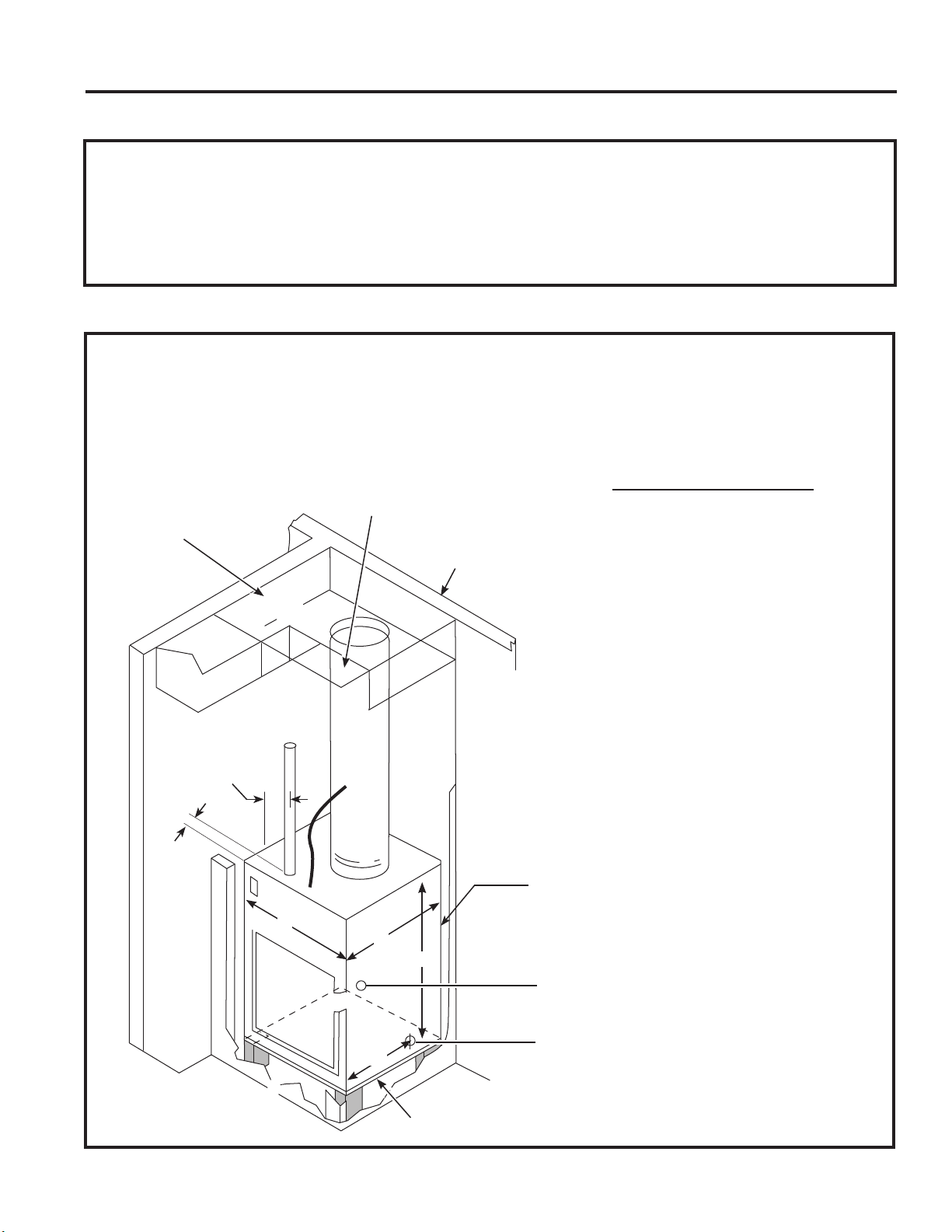
Ductwork
7KHVXSSO\GXFWV\VWHPVKRXOGEHGHVLJQHGYLD
a recognized method such as the equal friction
method, or velocity reduction method, using the
appropriate duct calculator(s) for the type(s) of duct
LHPHWDOGXFWGXFWERDUGRUIOH[GXFWEHLQJXVHG
LQWKHV\VWHP7KHGXFWV\VWHPVKRXOGEHGHVLJQHG
IRUDPD[LPXPIULFWLRQUDWHRI´ZDWHUFROXPQ
taking into consideration all fittings, registers and/or
diffusers. DO NOT operate unit without a supply
duct attached.
7KHUHWXUQDLUWR6398VHULHVXQLWV0867127EH
GXFWHGDQGDOOXQLWV0867KDYHDIUHHUHWXUQDLU
configuration to perform properly.
7KHWRWDOIORZUDWH&)0DQGH[WHUQDOVWDWLFSUHVVXUH
(ESP) available can be estimated from the chartsto
the left. Use these charts to select your fan speed
setting.
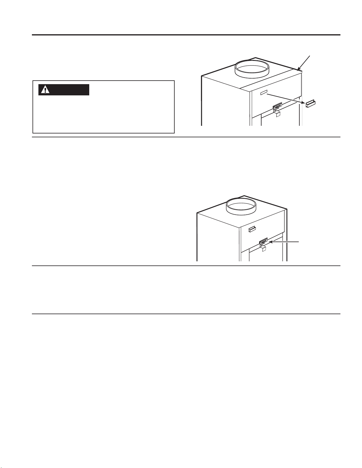
7KHFROODURQWRSRIWKHXQLWDFFHSWVVWDQGDUG
´
duct.
3XOODOOGXFWWLJKW([WUDGXFWVODFNFDQJUHDWO\
increase static pressure.
NOTICE: Flex duct can collapse and
cause airflow restrictions. Do not use flex duct
for 90° bends or unsupported runs of 5 ft. or
more.
Indoor Air Flow Data
,QGRRUDLUIORZPD\EHGHWHUPLQHGE\PHDVXULQJWKH
H[WHUQDOVWDWLFSUHVVXUH(63RIWKHGXFWV\VWHP
using an inclined manometer or magnehelic gauge,
WKHQFRQVXOWLQJFKDUW³$´WRGHWHUPLQHDFWXDODLUIORZ
Use the air flow correction multipliers contained in
FKDUW³%´WRGHWHUPLQHDFFXUDWHDLUIORZXQGHUWKH
listed conditions. Under no circumstances should
WKH6398HTXLSPHQWEHRSHUDWHGDWDQH[WHUQDO
VWDWLFSUHVVXUHLQH[FHVVRI´:&2SHUDWLRQ
of the SPVU under these conditions will result in
inadequate air flow leading to poor performance and/
or premature component failure.
Chart A - CFM - Determining the Indoor CFM
Models
$=+$=+
Fan
Speed Low High
(63³ SCFM
´
´
´
´
´
(63 H[WHUQDOVWDWLFSUHVVXUHLQLQFKHVZDWHUFROXPQ
Rated CFM at Low Speed:
$=+ $=+
For single speed thermostats connect to the GL terminal for
/RZ6SHHGRU*+WHUPLQDOIRU+LJK6SHHG7ZRVSHHGFRQWURO
thermostats will use both terminals.
Chart B - Correction Multipliers
Correct CFM (if needed)
Correction Multipliers for:
99
9
Heating
Cooling
Your airflow should be balanced based on many
factors, such as available ESP, room CFM, and
ductwork. Consult an HVAC engineer for proper
DSSOLFDWLRQV([WHUQDOVWDWLFSUHVVXUH(63FDQEH
measured with a manometer or pitot tube. Once this
ESP is established, you can calculate the CFM using
the above chart.
Higher CFMs tend to increase 6(16,%/(capacity,
enhance room circulation and increase duct noise,
while lower CFMs tend to increase /$7(17capacity
and reduce noise.


 null")