GE Everest Ca-Zoom 6.2 User manual

GE
Inspection Technologies Remote Visual Inspection
Everest Ca-Zoom®6.2
Operating Manual
www.ge.com/inspectiontechnologies

Everest Ca-Zoom®6.2
Preface
Overview of Manual
Congratulations! You now have one of the most advanced technology available for
remote visual inspection. The Everest Ca-Zoom 6.2 Digital Inspection System is
the first fully digital inspection camera system available on the market for industrial
applications. With its advanced iV
IEW
™ software technology, unique features such
as your choice of camera head diameter, and ease of operation combine to make the
Everest Ca-Zoom 6.2 Digital Inspection System the newest innovation in remote visual
inspection. Thank you for your business.
This manual provides you with all necessary information you need to operate and
maintain the Everest Ca-Zoom 6.2 Digital Inspection System. The manual will assist
you to optimize your inspections and was developed to help all levels of operators
learn quickly and precisely.
In addition, the manuals appendices provide fast references to any questions or
problems you might encounter. Should you have any questions beyond the scope of
this manual, please call your local sales representative or our customer service depart-
ment (listed on back cover), either of whom will be happy to help you.
1

Everest Ca-Zoom®6.2
1. Warning and Precautions...................... 3
.
2. System Symbol Description ................. 7
3. Features and Benefits .......................... 8
4. Applications ...........................................8
5. Helpful Hints .......................................... 9
6. System Overview .................................. 9
6.1 System .......................................... 9
6.2 Standard System .........................10
6.3 Optional Component ....................10
7. System Components ...........................11
7.1 Camera Control Unit ....................11
7.2 Camera Head .........................11-12
7.3 Hand-held Controller ..................12
8. System Setup ......................................13
8.1 Attaching HH Controller Cable.....13
8.2 Attaching the Camera Cable........14
8.3 Attaching Strain Relief Cable .....14
8.4 Attaching Slip Ring Cable
Reel ............................................15
8.5 Attaching other PeripheralDevices.15
8.6 System Power ............................15
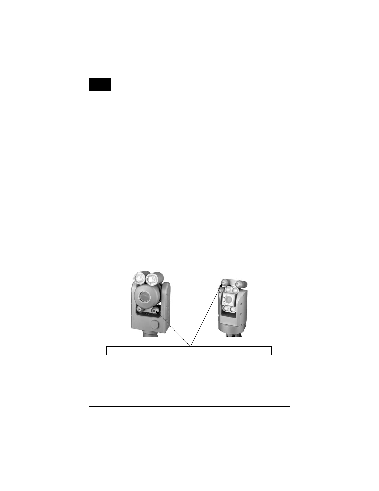
8.7 Laser Installation PTZ100............16
8.8 Laser Installation PTZ140............17
9. Operation Procedures ....................... 18
10. Hand-Held Controls ...........................19
11. Menu Features .................................. 27
11.1 SAVE IMAGE ................................ 27
11.2 ANNOTATION ............................... 29
12. Main Menu Operation ......................
36
12.1 GO TO HOME................................37
12.2 CAMERA SETUP Menu ................37
12.3 LASERS ..................................... 43
12.4 POSITIONS ................................. 43
12.5 SPLIT SCREEN ............................45
12.6 VIDEO RECORD ...........................48
12.7 FILE MANAGER Menu ................
50
12.8 SETUP Menu .............................
58
Table of Contents
13. Measurement Operations ............... 67
14. Maintenance ......................................71
14.1 Cleaning .................................... 71
14.2 Storage & Shipment .................. 71
14.3 Lamp & Lamp Window
Replacement - PTZ140............... 71
14.4 Camera Window
Replacement - PTZ140............... 72
14.5 Camera Module
Replacement - PTZ140...............73
14.6 Lamp Window
Replacement - PTZ100............... 75
14.7 Camera Window
Replacement - PTZ100.............. 76
14.8 Camera Module
Replacement - PTZ100...............77
14.9 Lamp Replacement - PTZ70...... 79
14.10 Camera Window
Replacement - PTZ70................ 80
14.11 Camera Module
Replacement - PTZ70.................81
14.12 Purging ....................................... 82
14.13 Pressure testing .........................82
15. Troubleshooting ............................... 83
16. Service .............................................. 84
17. Warranty............................................. 85
18. Appendices ........................................86
A - Specifications ...............................86
B - Software......................................... 90
C - Legacy ......................................... 91
D - New System Default Settings.........92
E - Accessories.................................. 92
F - Manual Image Control Features......93
G - Laser Accessory Calibration ..........94
H - Agency Certification..................... 96
I - System Configuration (w/cable)......97
J - System Configuration (no cable).....98
K - Spare Part List ..............................99
L - Chemical Compatibility.................101
M - Creating a Logo Bitmap File ........102
N - Environmental Compliance ........ 103
2

Everest Ca-Zoom®6.2
Please Read
To ensure operators safety, be sure to read and understand this User’s Manual before using any
of this equipment!
Possible Explosion Hazard
The Everest Ca-Zoom 6.2 Digital Inspection System camera and its accessories are not explo-
sion-proof, pressurized, or intrinsically-safe. Do not use in hazardous environments as defined in
NFPA 70 National Electrical Code, or IEC 79-10, or EN60079-10.
Accessories
The accessories listed in this manual are the only accessories that the manufacturer considers
being suitable for use with this product.
Electrical Shock Hazard
Electrical shock hazard exists due to high internal voltage. The Everest Ca-Zoom 6.2 CCU should
never be misused or exposed to hazardous environments. There are no serviceable parts inside
the CCU. The CCU should never be forced open or misused. The Hand-held Controller housing and
cable connectors should never be exposed to hazardous environments. There are no serviceable parts
inside these mentioned components. Refer all service to listed Service Centers (see “Service”).
Environmental
The Everest Ca-Zoom 6.2 Digital Inspection System camera head and cable are for in-air or
underwater use. The CCU and Hand-held Controller should not be used in wet environments as
their materials are not waterproof.
Earth Ground Required/ Warning, Electrical Shock Hazard: Proper use of this product requires
the presence of a protective earth ground path at the AC power source. Use of two-conductor
extension cords or any other action that may result in the loss of this ground path are in violation
of the product’s safe operating requirements.
Warning
Always turn off main power switch before disconnecting the AC power source.
1 Warnings and Precautions
3

Everest Ca-Zoom®6.2
Warning
Use of any piece of this equipment in a manner not specified by the manufacturer may impair the
product’s ability to protect the user from harm.
Warning
The Everest Ca-Zoom 6.2 Digital Inspection System and accessories should never come in direct
contact with any voltage or current source. Damage to the equipment and/or electrical shock to
the operator may result!
The Everest Ca-Zoom 6.2 Digital Inspection System may be disconnected from the AC power
main supply by disconnecting the power cord from the main power source.
Warning
Image may become distorted and unuseable between 95 and 145 MHz at a field strength of
greater than 10V/M.
Warning
Parallel Laser Accessory: avoid inadvertent exposure to hazardous laser radiation
• Prevent direct eye exposure to beam
• Ensure that the beam is always terminated at a suitable non-specular (i.e. non mirror-like)
surface
• Do not direct the beam at other people or into areas where other people may be present
Divergence of the beam : the laser beam divergence is less than 5 m/radians
4

Everest Ca-Zoom®6.2
Lisez
Pour assurer la sécurité de l’opérateur, prenez bien soin de lire et de comprendre ce manuel de
l’utilisateur avant de vous servir de l’appareil.
Risque D’Explosion
Le système d’inspection digital Everest Ca-Zoom 6.2 et ses accessoires ne sont pas antidéfla-
grants, pressurisés ou intrinsèquement sans danger. Ne pas utiliser dans un environnement
dangereux tel que décrit dans le NFPA 70 du Code National Électrique ou le IEC 79-10 ou le
EN60079-10.
Accessoires
Les accessoires énumérés dans le présent manuel sont les seuls accessoires que le fabricant
considère appropriés à l’usage de ce produit
Risque de Choc Électrique
Le risque de choc électrique existe à cause du haut voltage interne. L’unité de contrôle informa-
tisé du Everest Ca-Zoom 6.2 ne doit pas faire l’objet d’une mauvaise utilisation ni être exposé à
un environnement dangereux.
Aucunes pièces à l’intérieur de l’unité de contrôle informatisé ne requièrent de service. L’unité
de contrôle informatiseé ne doit jamais être ouverte de force ni faire l’objet d’une mauvaise
utilisation. Le boîtier du moniteur et les connecteurs du câble ne doivent jamais être exposés
à un environnement dangereux. Il n’y a aucunes pièces qui requièrent du service à l’intérieur
de ces composantes. Référer toute demande de service à la liste des centres de services (voir
«Service»).
Environement
La tête de la caméra et le câble du système d’inspection digital Ca-Zoom PTZ 6.2 sont conçus
pour l’utilisation à l’air libre ou sous l’eau. L’unité de contrôle informatiseé et le moniteur ne
doivent pas être en contact avec de l’eau puisqu’ils ne sont pas étanches.
Fiche de mise à la terre requise/Avertissement, Risque de choc électrique : L’utilisation correcte
de ce produit requière une fiche de mise à la terre à la source d’alimentation CA.
L’utilisation d’une rallonge électrique à deux branchements ou n’importe quelles actions qui
pourraient avoir comme conséquence la perte de la mise à la terre sont en violation avec les
recommandations d’utilisations du produit.
5
1 AVERTISSEMENTS ET PRÉCAUTIONS D’EMPLOI

Everest Ca-Zoom®6.2
Avertissement
Toujours fermer le bouton d’alimentation principal avant de débrancher le courant CA.
Avertissement
L’utilisation de toute pièce de cet équipment d’une façon non décrite par le fabricant risque de
nuire à la capacité du produit de protéger l’utilisateur contre des blessures.
Avertissement
Le systèm d’inspection digital Everest Ca-Zoom 6.2 et ses accessories ne doivent jamais entrer
en contact direct avec une cource de courant ou avec du voltage. Ceci pourrait causer des dom-
mages à l’équipment ou donner des chocs électriques à l’opérateur!
Le systèm d’inspection digital Everest Ca-Zoom 6.2 peut être débranché du courant d’alimentation
CA en débranchant le cordon d’alimentation de la source de courant.
Avertissement
L’image peut devenir déformée et inutilisable entre 95 et 145 Mhz dans des champs de plus de
10V/M.
Avertissement
Pointeurs laser parallèles: exposition à de la radiation laser dangereuse.
• Prévenir l’exposition directe des yeux aux faisceaux
• S’assurer que le faisceau se termine sur une surface non réfléchissante (ex: miroir)
• Ne pas diriger le faisceau sur des personnes ou dans un endroit où il peut y avoir des per-
sonnes
6
Divergence des faisceaux: La divergence des faisceaux est moins de 5 m/radians

Everest Ca-Zoom®6.2
2 System Symbol Description
CAUTION: REFER TO USER’S
MANUAL
CAUTION: SURFACES MAY BE HOT
FUSE INFORMATION: REPLACE ONLY
WITH SAME TYPE AND RATING
ATTENTION: REPORTEZ-VOUS
AU MANUEL DE L’UTILISATEUR
ATTENTION: LES SURFACES
PEUVENT ÊTRE CHAUDES
INFORMATION SUR LE FUSIBLE:
REMPLACEZ UNIQUEMENT AVEC LE
MÊME TYPE ET MÊME CAPACITÉ
Description des Symboles
7
10AF 250V
10AF 250V
Caution - Use of controls or adjustments or
performance of procedures other than those
specified herein may result in hazardous
radiation exposure
ATTENTION: L’utilisation de contrôle,
d’ajustement ou de procédures autres que
celles précitées peuvent causer une exposi-
tion à de la radiation dangereuse.

Everest Ca-Zoom®6.2
3 Features and Benefits
Three Camera Head Diameter Options to provide inspection tools for large area viewing and in
cases where access is limited to small openings. Camera heads are interchangeable and operate
from same camera control unit and Hand-held Controller.
• PTZ140 Camera head features 25x optical zoom / 12 x Digital, 300:1 Total
• PTZ100 Camera head features 10x optical zoom / 4 x Digital, 40:1 Total
• PTZ70 Camera head features 10x optical zoom / 4 x Digital, 40:1 Total
Exclusive iV
IEW
™technology platform delivers the most advanced digital imaging and measure-
ment capabilities around, with still or video inspection recordings that can be sent to any PC in
the world.
Remote operation with Hand-held Controller with built in color-VGA LCD monitor to control zoom,
lighting, image control, and extensive menu functions for image management.
Dual-function joystick for camera movement and software menu control and an on-board file
manager
Measurement capability with parallel laser accessory mounted on the camera head provides a
reference measurement on a perpendicular surface.
Portable shipping case, just plug it in and in 30 seconds, you’re ready to inspect, with advanced
viewing capabilities at your fingertips.
8
4 Applications
Nuclear
• Nuclear Fuel and Serial Number Verification
• Reactor Vessel
• On-line Monitoring
• Large Pipes
• Remote Monitoring of Contaminated Rooms
• Steam Generator Bowl and Secondary-Side Inspection
• Remote Tooling Monitoring
• IWE/IWL Code Inspection
• Reactor Coolant Pump
• CRDM and BMI Inspection
Process and General Industrial
• Tank and Vessel • General Plant Maintenance
• Weld Inspections • Refractory Linings
• Corrosion Evaluation • Lined Vessels
• Coke Drum Lining Inspection • Fractionation Towers
• Floating Roof Inspection

Everest Ca-Zoom®6.2
6 System Overview
6.1 System
9
5 Helpful Hints
• Prior to any inspection, familiarize yourself with the Hand-held Controller buttons, fea-
tures, joystick navigation in order to save you time during inspection.
• Clean the camera window regularly. In most cases a poor image is due to dirt on the
camera window lens.
• Always allow sufficient time for camera head to cool before placement in storage/
shipping case.
iV
IEW
™ Hand-Held
Controller
Camera
Control Unit (CCU)
Rugged Shipping/Storage Case
Wheels
Retractable
Case Handle
Ca-Zoom Camera
with Integrated
Lights and Pan & Tilt
(comes with PTZ140,
and/or PTZ100,
and/or PTZ70 Camera
Heads)

Everest Ca-Zoom®6.2
10
6.2 Standard System
• Ca-Zoom camera with integrated lights and pan & tilt
• Camera Control Unit (CCU)
• iV
IEW
Hand-held Controller with LCD monitor
• 30 m (100 ft.) Camera Cable
• 5 m (16 ft.) Hand-held Control Cable
• AC Power Cable
• Tool Kit
• Operator Manual and Setup instructions
• Shipping/Storage Case
6.3 Optional Components
• Parallel Laser Measurement Accessory (PTZ140/PTZ100)
• iV
IEW
Remote Software for Controlling Ca-Zoom camera from a PC
• Sony GV-D1000 Digital VCR
• CO
2
Pressurization Kit
• Telescoping and Interconnecting Poles
• Tripod
• Swivel/Manway Tripod
• Rackmount Consoles
• Cable Reel
• Camera Head Stand
• Keyboard
• Extension Cables for Operation up to 500 m (1640 ft.)
• Extra Hand-held Controller
• Shipping/Storage Case for Cable Assembly

Everest Ca-Zoom®6.2
&!
(Z
6
!
2%0,!#%&53%!3-!2+%$
#OMPLIESWITH#&2ANDEXCEPTFOR
THEDEVIATIONSPURSUANTTO,ASER.OTICE.ODATED
*ULY
530ATENTS
7 System Components
7.1 Camera Control Unit
11
Keyboard Connection
Coaxial Video Out
S-Video Out
Coaxial Video In
S-Video In
USB Video Output
Hand-held
Controller
Connection
Camera
Connection
System Power
On/Off
7.2 Camera Head Options
AC Power
RS-232 Cable
Pan & Tilt Housing
2 X 35 Watt Lights
Schrader Valve Cap
Camera lens
Pan & Tilt Housing Schrader Valve Cap
Camera lens
4x5W LED
Lights
PTZ140 PTZ100
CompactFlash Drive
AC Fuse

Everest Ca-Zoom®6.2
12
7.3 Hand-held Controller
:OOM :OOM
&/#53
,)'(43
)-!'%
3AVE &REEZE
%.4%2
%8)4
-%.5
Lights
Image
Focus
Multi-function joystick
Exit
Enter
Menu
Freeze
Save
Power (LCD)
Audio Level
Zoom
Microphone
7.2 Camera Head Options (Continued)
Pan Housing
8 X 5 Watt Lights
Schrader Valve Cap
Camera lens
PTZ70
Tilt Mechanism
LDC Monitor
Speakers
Soft Buttons
(8 total)

Everest Ca-Zoom®6.2
13
8 System Setup
Step 1. Remove the Hand-held Controller and Hand-held Controller’s cable from the
system’s case.
Step 2. Attach the Hand-held Controller cable to the Hand-held Controller by aligning
the red dot on the cable to the small keyway on the Hand-held Controller and
push in. The ferrite bead on the cable is to be oriented toward the Hand-held
Controller.
Step 3. Attach the other end of the Hand-held Controller cable to camera control by align-
ing the red dot on the cable to the small keyway on the CCU.
Before setting up the system for use make sure the CCU, Camera Head and Hand-held Controller
are placed on a sturdy surface.
8.1 Attaching Hand-held Controller Cable
Hand-held Controller Cable Connection

Everest Ca-Zoom®6.2
14
8.3 Attaching Strain Relief Cable
The Strain Relief Cable Prevents damage to the camera connector. It must be used
whenever the camera hangs from the cable.
Step 1. Use a hex wrench to connect the two strain relief cables to opposite ends of the
camera head base.
Step 2. Use a hex wrench to remove the four screws from the strain relief collar.
Step 3. Place strain relief collar around main cable ensuring rubber grommet remains in
collar.
Step 4. Insert the four collar screws back in collar. Screw the screws in only one to two
rotations.
Step 5. Pull main cable through collar to create a slack loop between collar and camera
head.
Step 6. Tighten collar screws.
Figure 4
8.2 Attaching Camera Cable to Camera and CCU
Step 1. Align the small key on the cable connector with the keyway inside the connec-
tor on the camera head. Push the cable in and turn the nut until it comes to a
hard stop (fig. 2).
Note: If the nut does not reach a hard stop, the cable may not be aligned correctly.
Realign the cable with camera head and repeat Step 1.
Step 2.Align the wide key on the cable connector (fig. 3) with the wide notch at the top
of the cable connector on the camera control unit. Push the cable in and turn
the nut until it locks in place.
Note: If the nut does not lock in place, the cable may not be aligned correctly. Realign
the cable with camera control unit and repeat Step 2.
Figure 2 Figure 3Figure 1

Everest Ca-Zoom®6.2
15
8.6 System Power
Power Cord
Attach the power cord to the receptacle in the back of the CCU. Plug the power cord into a
properly grounded power source.
Turn ON power switch
CAUTION: Do not turn on power with cables disconnected.
8.5 Attaching other Peripheral Devices
Keyboard
For text generation, attach supplied keyboard to connection located in front of the CCU
labeled Keyboard.
Note: The keyboard may be plugged in or removed after the PTZ has been turned on.
Output Devices (Monitors, VCR, others)
For connection of output devices, determine the type of video cable required for proper
connection (S-Video or coaxial BNC). Connect the end of the video cable to the appropriate
video-out receptacle in the front of the CCU. Connect the opposite end of the same video
cable to the appropriate video-in receptacle of the output device.
Input Devices
For connection of input devices, determine the type of video cable required for connection
(S-Video or coaxial BNC). Connect the end of the video cable to the appropriate video-in
receptacle in the front of the CCU. Connect the opposite end of the same video cable to
the appropriate video-out receptacle of the input device.
8.4 Attaching Slip Ring Cable Reel (Optional)
Step 1. Align the wide key on the female end of the patch cable (fig. 5) with the wide
notch on the top of the connector on the cable reel. Push the cable in and turn
the nut until it locks in place (fig. 6).
Step 2. Align the wide key on the cable termination with the top of the cable connector
on the CCU. Push the cable in and turn the nut until it locks into place.
Figure 6Figure 5

Everest Ca-Zoom®6.2
16
8.7 Laser Accessory Installation (PTZ100)
Step 1. Locate the Schrader air valve on the pan and tilt section of the camera. Remove
the Schrader air valve cover.
Step 2. Release the pressure from the camera head
Step 3. Remove the screw from the laser mounting port on camera head (fig. 8)
Step 4. The laser accessory has a wire and connector assembly. Place the mounting plate
over the end of the harness. Make sure the “O” ring is in place on laser mounting
plate (fig. 8).
Step 5. Connect to mating connector from camera head (fig. 9).
Step 6. Align the mounting holes in the laser attachment with the mounting plate and
thread holes in the camera housing. Place laser attachment flush to mounting sur-
face and tighten mounting screws (fig. 10).
In order to insure the integrity of the camera system with laser accessory, the camera head needs
to be pressure tested. See “Pressure Testing” section on page 82.
Figure 7
Figure 9 Figure 10
Figure 8

Everest Ca-Zoom®6.2
17
8.8 Laser Accessory Installation (PTZ140)
Step 1. Locate the Schrader air valve on the pan and tilt section of the camera. Remove
the Schrader air valve cover.
Step 2. Release the pressure from the camera head (fig. 11)
Step 3. Remove the three screws from the laser mounting plate on camera head (fig. 12)
Step 4. The laser accessory has a wire and connector assembly. Connect to mating con-
nector from camera head (fig. 13)
Step 5. Make sure the ‘o’ ring is in place on laser mounting plate. Place laser accessory
flush to mounting plate surface and tighten mounting screws (fig. 14)
In order to insure the integrity of the camera system with laser accessory, the camera head needs
to be pressure tested. See “Pressure Testing” section on page 82.
Figure 11 Figure 12
Figure 13 Figure 14

Everest Ca-Zoom®6.2
18
1. Place Ca-Zoom PTZ case on sturdy surface.
2. Take out AC power cable and connect to power outlet. If possible, use AC power cord
in combination with a GFI protector.
3. Connect Hand-held Controller cable to Hand-held Controller and CCU.
4. Connect camera cable to camera and CCU.
5. Attach strain relief cable.
6. Place camera on mounting pole.
7. Insert new a CompactFlash®card into the CompactFlash drive.
8. Connect other peripherals as needed.
9. Turn on the green power switch. When system power is on, the green power switch
will illuminate.
10. Allow approximately 30 seconds for software boot.
11. Your are now ready for your inspection.
9 Operation Procedures

Everest Ca-Zoom®6.2
19
Joystick Overview
The joystick is used to control the PTZ camera motion and navigate through the menu selection
on the hand-held contoller’s LCD. The left and right joysticks will both be simultaneously active.
Hence, contradictory joystick movement will result in the camera dithering (camera moving back
and forth). Both joysticks will also operate identically, which will enable right-handed or left-
handed operation. Pressing the joystick in will have the same results as pressing the ENTER
button on the Hand-held Controller. Please be advised that camera pan/tilt speed is proportional
to joystick motion. However, the higher level of joystick motion will not have an effect on speed
of menu selection. The pan-tilt speed will be proportional to zoom level (Camera head rev. 4.3 or
higher). If the camera is mounted upside-down, a setup option “Invert Camera” is used to restore
the intuitive up, down, left and right joystick movements.
Joystick - Menu Navigation
The joystick is used to navigate through the various menus. Up/Down joystick movements
navigate up and down the menu while Left/Right joystick movements access “drop-down” menu
features which appear on-screen associated with primary menu options.
Menu Access
• Press MENU button
Menu Navigation
• Use joystick to move the cursor to desired item
• To select a field, move the joystick up or down until it is highlighted (changes color).
• To change the values or option in a field, move the joystick left or right until the desired
setting is highlighted.
Drop Down Menus
• If there is a drop-down menu associated with an item in a menu, a “ ” character will
appear after the menu item. Example: LIVE ANNOTATION
To Accept Menu Setting
• Press the ENTER button (unless screen instructions indicate alternate methods).
To Accept Menu Setting
• Press the MENU button a second time to return to previous operational mode (unless
screen instructions indicate alternate methods).
• Or, press EXIT button to return to default live viewing mode.
10 Hand-held Controls
Table of contents
Other GE Analytical Instrument manuals
Popular Analytical Instrument manuals by other brands

Servomex
Servomex SERVOTOUGH SpectraExact 2500 Quick start manual

Keysight
Keysight N5241AU-927 Installation note

Steinberg Systems
Steinberg Systems SBS-EC-10 user manual

Anritsu
Anritsu MS2711B user guide

Eddyfi Technologies
Eddyfi Technologies TSC U41 user manual

Milwaukee
Milwaukee AIC2 Original instructions