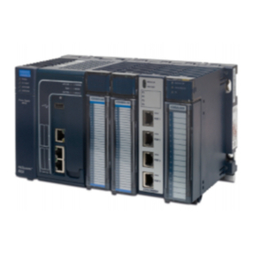
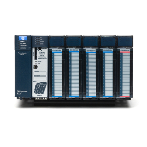
GE PACSystems* RX3i User manual

GE
Intelligent Platforms
Programmable Control Products
PACSystems* RX3i
IEC 104 Server
Module IC695EIS001
User Manual
GFK-2949C
July 2017
g

Legal Information
Warnings, Cautions, and Notes as Used in This Publication
Warning
Warning notices are used in this publication to emphasize that hazardous
voltages, currents, temperatures, or other conditions that could cause personal
injury exist in this equipment or may be associated with its use.
In situations where inattention could cause either personal injury or damage to
equipment, a Warning notice is used.
Caution
Caution notices are used where equipment might be damaged if care is
not taken.
Note: Notes merely call attention to information that is especially significant to understanding and
operating the equipment.
These instructions do not purport to cover all details or variations in equipment, nor to provide for
every possible contingency to be met during installation, operation, and maintenance. The
information is supplied for informational purposes only, and GE makes no warranty as to the accuracy
of the information included herein. Changes, modifications, and/or improvements to equipment and
specifications are made periodically and these changes may or may not be reflected herein. It is
understood that GE may make changes, modifications, or improvements to the equipment referenced
herein or to the document itself at any time. This document is intended for trained personnel familiar
with the GE products referenced herein.
GE may have patents or pending patent applications covering subject matter in this document. The
furnishing of this document does not provide any license whatsoever to any of these patents.
GE PROVIDES THE FOLLOWING DOCUMENT AND THE INFORMATION INCLUDED THEREIN AS-IS AND
WITHOUT WARRANTY OF ANY KIND, EXPRESSED OR IMPLIED, INCLUDING BUT NOT LIMITED TO ANY
IMPLIED STATUTORY WARRANTY OF MERCHANTABILITY OR FITNESS FOR PARTICULAR PURPOSE.
* Indicates a trademark of General Electric Company and/or its subsidiaries.
All other trademarks are the property of their respective owners.
Copyright © 2014-2017 General Electric Company. All Rights Reserved

Contact Information
If you purchased this product through an Authorized Channel Partner, please contact the seller
directly.
General Contact Information
Online technical support and
GlobalCare
http://support.ge-ip.com
Additional information
http://www.ge-ip.com/
Solution Provider
solutionpr[email protected]
Technical Support
If you have technical problems that cannot be resolved with the information in this manual, please
contact us by telephone or email, or on the web at http://support.ge-ip.com
Americas
Online Technical Support
http://support.ge-ip.com
Phone
1-800-433-2682
International Americas Direct Dial
1-780-420-2010 (if toll free 800 option is unavailable)
Technical Support Email
Customer Care Email
customercar[email protected]
Primary language of support
English
Europe, the Middle East, and Africa
Online Technical Support
http://support.ge-ip.com
Phone
+800-1-433-2682
EMEA Direct Dial
+420 239015850 (if toll free 800 option is unavailable or if
dialing from a mobile telephone)
Technical Support Email
Customer Care Email
customercar[email protected]
Primary languages of support
English, French, German, Italian, Czech, Spanish
Asia Pacific
Online Technical Support
http://support.ge-ip.com
Phone
+86-400-820-8208
+86-21-3877-7006 (India, Indonesia, and Pakistan)
Technical Support Email
Customer Care Email
customercar[email protected]

Contact Information


GFK-2949C July 2017 i
Table of Contents
TABLE OF CONTENTS ...............................................................................................................................................I
TABLE OF FIGURES................................................................................................................................................. IV
CHAPTER 1INTRODUCTION................................................................................................................................1
1.1 REVISIONS IN THIS MANUAL .................................................................................................................................................1
1.2 IEC 104 OVERVIEW...............................................................................................................................................................2
1.3 DESCRIPTION...........................................................................................................................................................................3
1.4 PRODUCT OVERVIEW.............................................................................................................................................................4
1.5 SPECIFICATIONS......................................................................................................................................................................5
1.6 CONTROLS AND INDICATORS................................................................................................................................................6
1.7 RX3I IEC 104 SERVER SPECIFICATIONS AND RESTRICTIONS.........................................................................................7
1.7.1 ADSU Supported in General Interrogation...................................................................................................7
1.7.2 ADSU Supported without Time Tag and RBE..............................................................................................7
1.7.3 ADSU Supported with 56-Bit Time Tag and RBE.......................................................................................7
1.7.4 ADSU Supported Commands.............................................................................................................................8
1.7.5 ADSU Supported Commands and Responses............................................................................................8
1.7.6 General Purpose ADSUs Supported................................................................................................................8
1.8 PERFORMANCE AND LIMITATIONS ....................................................................................................................................10
1.8.1 General Restrictions ............................................................................................................................................10
1.8.2 Point Count Restrictions ....................................................................................................................................10
1.8.3 Point Event Count Restrictions .......................................................................................................................10
1.9 GLOSSARY.............................................................................................................................................................................11
1.10 REFERENCES.........................................................................................................................................................................12
CHAPTER 2INSTALLATION............................................................................................................................... 14
2.1 PRE-INSTALLATION CHECK................................................................................................................................................15
2.2 INSTALLATION LOCATION...................................................................................................................................................15
2.3 INSTALLATION IN HAZARDOUS AREAS .............................................................................................................................16
2.3.1 ATEX Zone 2............................................................................................................................................................16
2.3.2 ATEX Marking .........................................................................................................................................................16
2.4 MODULE INSTALLATION .....................................................................................................................................................17
2.4.1 Mounting the EIS001...........................................................................................................................................17
2.4.2 EIS001 Module Removal....................................................................................................................................17
2.5 SPARE PARTS........................................................................................................................................................................17
CHAPTER 3CONFIGURATION........................................................................................................................... 18
3.1 CONFIGURATION TOOLS.....................................................................................................................................................19
3.2 RX3I RACK/SLOT HARDWARE CONFIGURATION ...........................................................................................................19
3.3 RX3I CPU SETTINGS...........................................................................................................................................................21
3.4 LAN INTERFACE STATUS BITS...........................................................................................................................................22
3.5 ETHERNET CONFIGURATION..............................................................................................................................................23
3.6IEC 104 SERVER CONFIGURATION ..................................................................................................................................24
3.7 STATION MANAGER CONFIGURATION..............................................................................................................................25
CHAPTER 4SYSTEM OPERATION...................................................................................................................... 26
4.1 SYSTEM OVERVIEW .............................................................................................................................................................26
4.1.1 Communications...................................................................................................................................................26

Contents
ii PACSystems RX3i Ethernet 104 Server Module User Manual GFK-2949C
4.1.2 Redundancy............................................................................................................................................................26
4.1.3 I/O Scans ..................................................................................................................................................................27
4.1.4 Alarms........................................................................................................................................................................27
4.1.5 Station Manager ...................................................................................................................................................27
CHAPTER 5DIAGNOSTICS................................................................................................................................ 28
5.1 STATUS DATA.......................................................................................................................................................................29
5.2 LIGHT-EMITTING DIODE (LED) INDICATIONS..................................................................................................................29
5.3 POWER-UP...........................................................................................................................................................................30
5.3.1 Problems during Power-Up .............................................................................................................................30
5.3.2 Firmware Update Mode.....................................................................................................................................30
5.4 MODULE FAULTS IN THE RX3I I/O FAULT TABLES ........................................................................................................31
5.4.1 Typical Fault Messages during Power-Up.................................................................................................32
5.4.2 Using Status Data for Troubleshooting ......................................................................................................33
5.4.3 Clearing the RX3i Fault Tables........................................................................................................................33
CHAPTER 6CONFIGURATION OF IEC 104 SERVER PARAMETERS USING COMMREQ........................................ 34
6.1 OVERVIEW ............................................................................................................................................................................35
6.2 REQUIRED CONFIGURATION PARAMETERS......................................................................................................................37
6.2.1 Standard COMMREQ Command Block Parameters..............................................................................37
6.2.2 Parameters for Client Station-Server Connection..................................................................................37
6.3 MEMORY TRANSLATION FEATURE CONFIGURATION PARAMETERS.............................................................................38
6.3.1 Parameters for Read Translation Table .....................................................................................................38
6.3.2 Parameters for Command Translation Table ..........................................................................................38
6.3.3 Configuration Examples for Address Translation..................................................................................39
6.4 OPTIONAL CONFIGURATION PARAMETERS......................................................................................................................44
6.4.1 Parameters for Filter Times..............................................................................................................................44
6.4.2 Parameters for Short and Long Pulse Durations...................................................................................44
6.4.3 Parameters for Server Status Space............................................................................................................45
6.4.4 IEC 104 Polled Object Parameters, and CPO Setting for ADSUs .....................................................46
6.4.5 Option Parameters...............................................................................................................................................50
6.5 POINT PUSH INTERFACE DEFINITION ...............................................................................................................................55
6.5.1 Interface Specification........................................................................................................................................55
6.5.2 Record Format.......................................................................................................................................................55
6.5.3 Interface Collection Mechanism.....................................................................................................................57
6.5.4 Point Push for Digital and Analog Data .....................................................................................................57
6.6 REQUIRED COMMREQ FUNCTION BLOCK PARAMETERS............................................................................................58
6.7 PROGRAM DOWNLOAD ......................................................................................................................................................58
6.8 IEC 104 COMMUNICATIONS START-UP..........................................................................................................................59
6.9 COMMREQ STATUS WORD CODES ...............................................................................................................................59
6.10 SECURITY ..............................................................................................................................................................................59
APPENDIX ADEFINITION OF THE STATUS AREA.................................................................................................. 60
A-1 GENERAL TABLE VIEW........................................................................................................................................................60
A-2 SPECIFIC AREAS OF STATUS...............................................................................................................................................61
A-2.1 Status of Read........................................................................................................................................................61
A-2.2 Status of a Client Connection..........................................................................................................................61
A-2.3 Point Push................................................................................................................................................................61
A-2.4 Events being stored.............................................................................................................................................61
APPENDIX BSTATION MANAGER STATUS .......................................................................................................... 62
APPENDIX CLOG MESSAGES TABLE .................................................................................................................. 64


Contents
GFK-2949C July 2017 iii
APPENDIX DDEVICE PROFILE............................................................................................................................ 66
D-1 REVISION HISTORY ..............................................................................................................................................................67
D-2 INTRODUCTION ....................................................................................................................................................................68
D-3 INTEROPERABILITY ...............................................................................................................................................................69
D-3.1 System or device...................................................................................................................................................69
D-3.2 Network configuration.......................................................................................................................................69
D-3.3 Physical layer..........................................................................................................................................................70
D-3.4 Link layer ..................................................................................................................................................................71
D-3.5 Application layer...................................................................................................................................................72
D-3.6 Basic Application Functions.............................................................................................................................80

Contents
iv PACSystems RX3i Ethernet 104 Server Module User Manual GFK-2949C
Table of Figures
Figure 1: IEC 104 Basic System Architecture.........................................................................................................................2
Figure 2: Application Showing two IEC 104 LANs Accessing RX3i through two EIS001 Modules................2
Figure 3: IC695EIS001 Front View...............................................................................................................................................4
Figure 4: IEC 104 Server Module EIS001 Features at a Glance.....................................................................................6
Figure 5: Adding Module to Rack/Slot location .................................................................................................................19
Figure 6: Selection of EIS001 for Installation......................................................................................................................20
Figure 7: CPU Configuration Showing Example of Scan Settings (Scan Tab) .....................................................21
Figure 8: EIS001 LAN Status Bits (Bits 11 & 13)..................................................................................................................22
Figure 9: PME Tab for Entering Ethernet Settings to be used by EIS001...............................................................23
Figure 10: Station Manager Configuration Tab (Showing Defaults)........................................................................25
Figure 11: WinLoader Utility Screen-Shot............................................................................................................................30
Figure 12: Typical Power-Up Controller Fault Table Entries Originated by EIS001..........................................32
Figure 13: Sample IEC 104 Server Memory Setup............................................................................................................35
Figure 14: Ladder Logic Used to Configure IEC 104 Server Parameters ..............................................................35
Figure 15: COMMREQ Parameters & Corresponding Read/Write Permissives (Case 1) ................................39
Figure 16: Red/Write Interaction between Controller and IEC104 Client (Case 1) ...........................................39
Figure 17: COMMREQ Parameters & Corresponding Read/Write Permissives (Case 2) ................................40
Figure 18: Red/Write Interaction between Controller and IEC104 Client (Case 2) ...........................................40
Figure 19: COMMREQ Parameters & Corresponding Read/Write Permissives (Case 3) ................................41
Figure 20: Red/Write Interaction between Controller and IEC104 Client (Case 3) ...........................................41
Figure 21: COMMREQ Parameters & Corresponding Read/Write Permissives (Case 4) ................................42
Figure 22: Red/Write Interaction between Controller and IEC104 Client (Case 4) ...........................................42
Figure 23: COMMREQ Parameters & Corresponding Read/Write Permissives (Case 5) ................................43
Figure 24: Red/Write Interaction between Controller and IEC104 Client (Case 5) ...........................................43
Figure 25: Example of CPO Splitting ADSU into Read-Only and Read/Write Segments................................46
Figure 26: Status Area Contents and Layout .....................................................................................................................60
Figure 27: Response to stat a Command.............................................................................................................................62
Figure 28: Node Commands Showing Available Plug-in Communication Modules .......................................63

GFK-2949C July 2017 1
Chapter 1 Introduction
This manual describes the RX3i IEC 60870-5-104 Option Parameters Ethernet Server Module,
IC695EIS001 (or EIS001 for short). By installing this module in the backplane of an RX3i controller, the
controller may be set up as an IEC 104 Server on an IEC 104 Network. This permits RX3i data to be
exchanged with the IEC 104 Clients on that network.
Introductory material may be found in this chapter. Chapter 2 provides installation and set-up
information. Chapter 3 provides configuration instructions. Chapter 4 describes system operation.
Chapter 5 provides diagnostic information. Chapter 6 covers the use and format of ladder logic
COMMREQ instructions used to set up and configure the EIS001 module and its interaction with the
IEC 104 Clients to which it is connected over Ethernet.
The appendices provide reference material for this application. Appendix D, Device Profile provides a
profile of the IEC 104 Server.
1.1 Revisions in this Manual
Rev
Date
Description
C
Jul-2017
The IEC-104 communication module IC695EIS001 firmware Release 1.40 provides enhancement to
enable Report by Exception of analog data without time stamp through ASDU13 spontaneously
instead of ASDU36, this enhancement makes use of unused bit 10 of Option parameter [67] as
described in section Option Parameters
B
Mar-2016
The section, Specifications updated
The section, Parameters for Client Station-Server Connection updated
The section, Option Parameters updated table and added new subsections Multiple Client Connection
Configuration and COMMREQ –Shift RBE on Client Connection Associated With a Specified Port Number
The section, Point Push for Digital Data removed
The section, Point Push for Digital and Analog Data table updated
A
Apr-2015
Addition of support for Memory Translation Feature and Control Point Offset.
-
Dec-2014
▪Original Issue

Chapter 1. Introduction
2 PACSystems RX3i Ethernet 104 Server Module User Manual GFK-2949C
1.2 IEC 104 Overview
IEC 104 is a client/server communications protocol originally developed for use in the electric
utility sector for power transmission and distribution systems. It has migrated
to other vertical
markets, and is now a general market protocol based on a 3-layer protocol scheme. IEC 104 is a
generational protocol coming from a foundation of the IEC 60870-5-101 protocol.
Figure 1: IEC 104 Basic System Architecture
Figure 2: Application Showing two IEC 104 LANs Accessing RX3i through two EIS001 Modules
HMI / SCADA
IEC104 Client
Enet
switch
PACSystems RX3i
IEC104 Server
(RTU)
Enet
switch
Ethernet Capable Net.
SCADA Master Station / Control
Center with IEC 104 Client
Engg. Station- PME
RX3i System
EIS001–IEC 104
Server Modules
HMI–IEC 104 Client
LAN1
104 LAN2

Chapter 1. Introduction
GFK-2949C July 2017 3
1.3 Description
The RX3i IEC 104 Server Module, catalog number IC695EIS001 (or EIS001), hosts the IEC 104 Server
protocol on a common RX3i ETM001 module hardware platform. Thus, many of the specifications
and behaviors are shared with the ETM001 module. IC695EIS001 is an Ethernet-connected module
which fits in the RX3i backplane and permits the RX3i to behave as a Server on the IEC 104 network.
The data exchanges between the EIS001 module and one IEC 104 Client are configurable, using a
single COMMREQ instruction in the ladder logic or Structured Text program, as detailed in Chapter 6,
and are limited to exchanging only linear (%) memory. Symbolic references, which represent non-
linear use of memory, cannot therefore be specified in this interface. However, the corresponding
data may be exchanged as part of a block of memory (%R, for instance).

Chapter 1. Introduction
4 PACSystems RX3i Ethernet 104 Server Module User Manual GFK-2949C
1.4 Product Overview
The PACSystems RX3i Ethernet IEC 60870-5-104 Server Module, catalog
number IC695EIS001 implements the IEC communications protocol. It
permits a PACSystems RX3i controller to be connected to an Ethernet
network using a standard TCP/IP connection scheme, allowing an IEC 104
Client to poll data from the Server, as well generate unsolicited
communications from the Server back to the Client.
Two auto-sensing 10BaseT/100BaseTX RJ-45 shielded twisted-pair
Ethernet ports permit direct connection to either a 10BaseT or 100BaseTX
IEEE 802.3 network without an external transceiver. Line, Star and Daisy
Chain topologies are supported.
The RX3i Ethernet IEC 104 Server Module hosts the IEC104 Server side
protocol on a common RX3i ETM001 module hardware platform. Thus,
many of the specifications and behaviors are shared with the ETM001
module including protocol support. IC695EIS001 is an Ethernet-connected
module that fits in the RX3i backplane and permits the RX3i to behave as a
Server on the IEC104 network. The data exchanges between the EIS001
module and IEC104 Client(s) are configurable, using a single COMMREQ
instruction in the ladder logic or Structured Text program.
Module Features
The Ethernet 104 Server Module:
•Supports up to eight connections to the RX3i Controller data set
specified in the configuration.
•Supports Interrogation and RBE for Single Point and Double Point data.
•Supports Interrogation and RBE for Regulated Step.
•Supports Interrogation and Measured data sets for Scaled, normalized,
and single precision Float.
•Supports 56-bit IEC 60870-5-104 time format, with the default being
56-bit time format.
•Supports Time Set, and query of the RX3i Controller CPU Clock in UTC
time.
•Cause of Transmission size is two octets.
The Ethernet 104 Server Module specifications:
•Up to four EIS001 per RX3i, as allowed by available power and slots.
•Module can be installed in any available RX3i main rack I/O slot.
•Module supports insertion into and removal from an RX3i backplane
which is under power.
•Firmware upgrade through RX3i CPU using WinLoader software utility.
ETHERNET OK
LAN OK
LOG EMPTY
EIS001
ETHERNET
RESTART
MAC IP
100 Mbps
Port 1B
LINK
100 Mbps
Port 1A
LINK
10/100 Mbps ETHERNET
STATION MGR
Figure 3: IC695EIS001 Front
View

Chapter 1. Introduction
GFK-2949C July 2017 5
1.5 Specifications
Module Name
PACSystems RX3i Ethernet 104 Server Module
Catalogue
IC695EIS001-AA
Protocol Supported
IEC60870-5-104 Server
Connectors
- Station Manager (RS-232) Port: 9-pin female D-connector
- Two 10BaseT / 100BaseTX Ports: 8-pin female shielded RJ-45
LAN
IEEE 802.2 Logical Link Control Class I
IEEE 802.3 CSMA/CD Medium Access Control 10/100 Mbps
Number of IP addresses
One
Number of Ethernet
Ports
Two. Both are 10BaseT / 100BaseTX with auto-sensing. Connectors are RJ-45.
Embedded Ethernet
Switch
Yes –Allows daisy-chaining of Ethernet nodes.
Serial Port
Station Manager Port: RS-232 DCE, 1200 –115,200 bps.
Modules per RX3i CPU
4
Number of 104 Clients
supported per module
8
Refer to the sections Multiple Client Connection Configuration and
COMMREQ –Shift RBE on Client Connection Associated With a Specified Port Number
Number of 104 Sectors
supported per module
One
Number of 104 Clients
supported per RX3i CPU
4 per RX3i CPU
Number of 104 points
per module
61441
Network Topology
supported
Star, Line, Daisy Chain
Hot Swappable
Yes
Time Synchronization
SNTP Client
Power Requirements
3.3Vdc: 0.840 A maximum
5 Vdc: 0.614 A maximum
For system standards, general operating specifications, and installation requirements, refer to
PACSystems RX3i System Manual, GFK-2314.
1
Two Protection objects (M_EP_TB_1 and M_EP_TC_1) are only accessible through Point Push and not as Controller points.
This constitutes 2048 points (1024 each) and is included in the total number of Points per Module.

Chapter 1. Introduction
6 PACSystems RX3i Ethernet 104 Server Module User Manual GFK-2949C
1.6 Controls and Indicators
Figure 4 shows the front of the module and identifies its controls and indicators.
ETHERNET OK
LAN OK
LOG EMPTY
EIS001
ETHERNET
RESTART
MAC IP
100 Mbps
Port 1B
LINK
100 Mbps
Port 1A
LINK
10/100 Mbps ETHERNET
STATION MGR
Status LEDs
Module ID
Restart
Pushbutton
Station
Manager
Port
RS-232
Address
ID Area
RJ-45
Connector
Ethernet
Ports (2)
10BaseT/
100BaseTX
Network
Speed LED
Network
Link OK LED
Figure 4: IEC 104 Server Module EIS001 Features at a Glance

Chapter 1. Introduction
GFK-2949C July 2017 7
1.7 RX3i IEC 104 Server Specifications and Restrictions
The following tables document the IEC 104 Server capabilities of the EIS001 module. Refer to the IEC
104 standard for details.
Interrogation Types
Description
General
General Interrogation is a full request of all point data on the Server from
the client.
RBE
Whenever a point changes state, an exception report is sent to the Client
of this event. Refer to Report By Exception Shutter Time
mComreq_Setup[12] in Parameters for Filter Times for details.
The IEC 104 Server does not buffer events, so a constant connection is
required in order to receive a report.
1.7.1 ADSU Supported in General Interrogation
ADSU
2
supported in General Interrogation
Mnemonic
Number
Description
M_SP_NA_1
1
Single-point information
M_DP_NA_1
3
Double-point information
M_ST_NA_1
5
Step position information
M_BO_NA_1
7
Bit string of 32-bit
M_ME_NA_1
9
Measured value, normalized value
M_ME_NB_1
11
Measured value, scaled value
M_ME_NC_1
13
Measured value, scaled value (Short Float)
M_EP_TB_1
18
Packed start events of protection equipment with time tag
M_EP_TC_1
19
Packed output circuit information of protection equipment with time tag
1.7.2 ADSU Supported without Time Tag and RBE
ADSU supported without time tag, and Report By Exception (RBE)
Mnemonic
Number
Description
M_ME_NC_1
13
Measured value, scaled value (Short Float) without time tag
1.7.3 ADSU Supported with 56-Bit Time Tag and RBE
ADSU supported with 56-bit time tag, and Report By Exception (RBE)
Mnemonic
Number
Description
M_SP_TB_1
30
Single-point information with time tag CP56Time2a
M_DP_TB_1
31
Double-point information with time tag CP56Time2a
M_ST_TB_1
32
Step position information with time tag CP56Time2a
M_BO_TB_1
33
Bit String of 32-bit with time tag CP56Time2a
M_ME_TD_1
34
Measured value, normalized value with time tag CP56Time2a
2
For definition of ADSU, refer to Glossary.

Chapter 1. Introduction
8 PACSystems RX3i Ethernet 104 Server Module User Manual GFK-2949C
M_ME_TE_1
35
Measured value, scaled value with time tag CP56Time2a
M_ME_TF_1
36
Measured value, scaled value with time tag CP56Time2a
M_EP_TE_1
39
Packed start events of protection equipment with time tag CP56Time2a
M_EP_TF_1
40
Packed output circuit information of protection equipment with time tag
CP56Time2a
1.7.4 ADSU Supported Commands
ADSU Commands
Mnemonic
Number
Description
C_SC_NA_1
45
Single command
C_DC_NA_1
46
Double command
C_RC_NA_1
47
Regulating step command
C_BO_NA_1
51
Bit String set command
C_SE_NA_1
48
Set-point Command, normalized value
C_SE_NB_1
49
Set-point Command, scaled value
C_SE_NC_1
50
Set-point Command, short floating point number
1.7.5 ADSU Supported Commands and Responses
ADSU Command and Responses
Mnemonic
Number
Description
C_SC_TA_1
58
Single command with time tag CP56Time2a
C_DC_TA_1
59
Double command with time tag CP56Time2a
C_RC_TA_1
60
Regulating step command with time tag CP56Time2a
C_BO_TA_1
64
Bit String Response with time tag CP56Time2a
C_SE_TA_1
61
Measured value, normalized value command with time tag CP56Time2a
C_SE_TB_1
62
Measured value, scaled value command with time tag CP56Time2a
C_SE_TC_1
63
Measured value, short floating point number command with time tag
CP56Time2a
Note: The commands are time tagged and only valid for the Command Age time.
Command Age: The value for this field is fixed to 5000 milliseconds. Time tagged commands must
have a time tag no older than this period or the control operation will not take place.
1.7.6 General Purpose ADSUs Supported
General Purpose ADSUs supported
Mnemonic
Number
Description
C_IC_NA_1
100
Interrogation command
C_CS_NA_1
103
Clock synchronization command

Chapter 1. Introduction
GFK-2949C July 2017 9

Chapter 1. Introduction
10 PACSystems RX3i Ethernet 104 Server Module User Manual GFK-2949C
1.8 Performance and Limitations
1.8.1 General Restrictions
Topic
Notes
Ethernet parameters
The IEC 104 server application code is developed on top of the RX3i ETM001
platform and is configured as an IC695EIS001 in the PME hardware
configuration. The module is limited to IPV4 addressing and can accept
AUP file settings for module parameters. Refer to the PACSystems RX7i &
RX3i TCP/IP Ethernet Communications User Manual, GFK-2224 for more
information.
1.8.2 Point Count Restrictions
Maximum Point Counts
ADSU
Maximum
Point Count
(in a Demo
Mode)
Maximum
Point Count
(when
licensed)
Memory Restriction
M_SP_NA_1
16
1024
Digital Memory Only
M_DP_NA_1
8
512
Digital Memory, where each 2 points is a byte
M_ST_NA_1
8
512
Analog Memory, 16-bit width per point
M_BO_NA_1
8
512
Word Memory, 32-bit width per point.
M_ME_NA_1
8
512
Analog Memory, 16-bit width per point
M_ME_NB_1
8
512
Analog Memory, 16-bit width per point
M_ME_NC_1
8
512
Word Memory, 32-bit width per point, “REAL” type
M_EP_TB_1
16
1024
Only accessible through Point Push
M_EP_TC_1
16
1024
Only accessible through Point Push
1.8.3 Point Event Count Restrictions
Maximum Event Counts
ADSU
When SOE for this
ADSU is enabled
Memory Restriction
M_SP_NA_1
2000 (Default -1024)
Digital Memory Only
M_DP_NA_1
2000 (Default -1024)
Digital Memory, where each 2 points takes a byte
M_ST_NA_1
2000 (Default - 512)
Analog Memory, 16-bit width per point
M_BO_NA_1
2000 (Default -1024)
Word Memory, 32-bit width per point.
M_ME_NA_1
2000 (Default - 512)
Analog Memory, 16-bit width per point
M_ME_NB_1
2000 (Default - 512)
Analog Memory, 16-bit width per point
M_ME_NC_1
2000 (Default - 512)
Word Memory, 32-bit width per point, “REAL” type
M_EP_TB_1
2000 (Default - 512)
Digital Memory Only (Only accessible through Point Push)
M_EP_TC_1
2000 (Default - 512)
Digital Memory Only (Only accessible through Point Push)

Chapter 1. Introduction
GFK-2949C July 2017 11
1.9 Glossary
ADSU
A generic term used for referring to a collection of data points, or a single data
point, on an IEC 104 device. An object can have a specific action on a Server and
all objects are defined in the IEC 104 Specification.
ASDU
Application Service Data Unit
AUP
Advanced User Parameters for Ethernet configuration, a file which contains
specific parameter overrides and options for the Ethernet Module.
COMMREQ
A Communications Request Instruction supported by RX3i CPUs. Conveys data
from the RX3i CPU to a designated target device. In this application, a single
COMMREQ conveys all the IEC 104 Server parameters to the EIS001.
CPO
Control Point Offset, a point index scheme by which the Server can protect data
from being over-written. It does so by only allowing points above a given index
value to be written to. Points at or below the index are read-only.
CRS
COMMREQ Status word.
CRU
A Controller (CPU) configured for Redundancy application.
IEC 104
The document term for the IEC60870-5-104 protocol specification.
IOA
Item of Activation, a term for a point which is the target object of a command.
IPv4
Internet Protocol version 4 (IPv4) is the fourth version in the development of the
Internet Protocol (IP), and routes most traffic on the Internet. IPv4 is described in
IETF publication RFC 791.
LAN
Local Area Network
LED
Light Emitting Diode
LIS
LAN Interface Status Bits are data provided by the module concerning the health
and status of its Ethernet interface. The status includes that of the physical
module as well as of the attached network.
PME
Proficy Machine Edition –used to configure, program and monitor RX3i Systems.
RBE
Report By Exception.
Segment
This term refers to the instance of data, the IEC 104 plug-in only supports one
data segment, as the Controller has only one memory space
Sessions
This term refers to the number of clients that can connect to the IEC 104 server.
The IEC 104 plug-in supports up to one.
ST
Structured Text: a programing language supported by RX3i CPUs.
SOE
Sequence Of Events: a generic term used to describe a mechanism that is capable
of detecting data change, then time-stamping each change for the purpose of
establishing the sequence in which the changes were detected.
TCP/IP
The Transmission Control Protocol (TCP) is one of the core protocols of the Internet
Protocol suite (IP), and is so common that the entire suite is often called TCP/IP.
TCP provides reliable, ordered and error-checked delivery of a stream of octets
between programs running on computers connected to a local area network,
intranet or the public Internet. It resides at the transport layer.
Other manuals for PACSystems* RX3i
9
Table of contents
Other GE Controllers manuals
Popular Controllers manuals by other brands

Delta Electronics
Delta Electronics Programmable Logic Controller DVP-SC instruction sheet

MR
MR TAPCON 230 quick guide

SALUPO
SALUPO EVO 1 AVM Instruction and installation manual

HP
HP Compaq Presario,Presario 4400 Replacement instructions

Instruo
Instruo tanh 3 user manual

Mitsubishi Electric
Mitsubishi Electric M800VS Series Connection and set up manual

KELCO
KELCO F60 Programming instructions

ARCA
ARCA MA60 Series Operating and maintenance manual

Firetrol
Firetrol Emerson Mark IIXG Installation and operation instructions

Sectoriel
Sectoriel TCR-02T manual

Monacor
Monacor img Stage Line CU-1RC manual

Siemens
Siemens SINUMERIK 802D sl Programming and operating manual