BASIC OPERATION AND FEATURES
SX TRANSISTOR CONTROL Page 7
October 1998
Function 4 and Function 8 of the Handset. The C/L setting is
based on the maximum thermal rating of the control.
Because of the flyback current through 3REC, the motor
current isusually greater than battery current, exceptat
100% ON time, or when the lA contactor is closed.
Section 2.1.3 Braking
Section 2.1.3.a Plug Braking
Slow down is accomplished when reversing direction by
providing a small amount of retarding torque for
deceleration. If the vehicle is moving, and the directional
lever ismoved from one direction to the other, theplug
signal is initiated. Once the plug signal has been initiated,
the field is reversed, and the armature current is regulated
to the plug currentlimit as setby Function 6. Armature
current is regulated by increasing the field current as the
vehicle slows down. Once the field current reaches a
preset value, set by Function 10, and armature plug current
can no longer be maintained, the braking function is
canceled, and the control reverts back to motoring.
All energy produced by themotor during plugging is
dumped as heatin the motor in this braking mode.
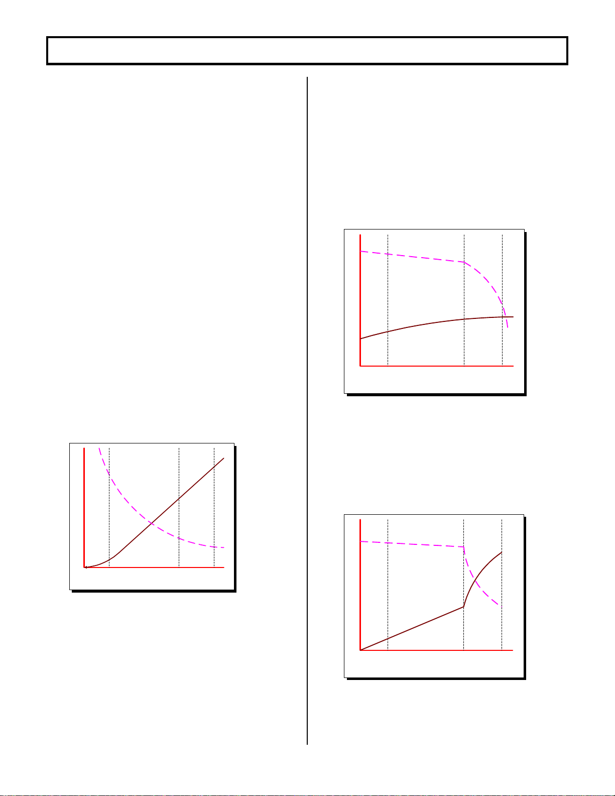
Section 2.1.3.b Regenerative Braking to Zero Speed
Slow down is accomplished when
reversing direction by providing a
small amount of retarding torquefor
deceleration. If the vehicle is
moving, and thedirectional lever is
moved from one direction to the
other, the regen signal is initiated.
Once the regen signal has been
initiated, the field current is
increased. Armature current is
regulated to the regen current limit
as set by Function 9. As the vehicle slows down, thefield
current continues to increase, and transistor Q2 begins to
chop. The field current will increase until it reaches a
preset value set by Function 10, and transistor Q2 on-time
will increase until it reaches 100% on-time. Once both of
the above conditions have been met, and regen current
limit can no longer be maintained, the braking function is
canceled. The fields will then reverse, and the control
reverts back to motoring.
Part of the energy produced by the motor during regen is
returned to the battery, and partis dumped in the motor as
heat.
Section 2.1.3.c PedalPosition Plug Braking
This feature allows control of the plugging distance based
on pedal position when there has been a “directional
switch" change. Pedal position will reduce the plugging
current to the "value set by this function" as the accelerator
is returned to the creep speed position. Maximum plug
current is obtained with the accelerator in the top speed
position. This featureis adjustable by using Function 16 on
the Handset.
Section 2.1.3.d Auto Braking
This featurecan be setup with the Handset using Function
17 to select "Auto Plug/Regen" . Thisfeature is enabled by
initiating a "neutral position" using either the directional
switch or the accelerator switch. Once activated, Auto
Braking operates similar to Pedal Position Plug Braking
and is adjusted by using Function 16 ofthe Handset.
Section 2.1.3.e Brake Pedal Regenerative Braking
This feature sets or varies the amount of REGEN current
with AUTO-REGEN braking feature. The current is variable
through the use of a pot on the brake pedal to provide a
minimum AUTO-REGEN braking level at pedal up, but
increasing as the pedal is depressed. A set level of REGEN
CURRENT LIMIT is available with a set resistor on the brake
pedal. An open inputwith either adjustment modea pot or
resistor will allowcoast until either is selected. Minimum
REGEN CURRENT LIMIT requires a 4200 ohm resistor input
(minimum level 50 amp). Maximum REGEN CURRENT LIMIT
requires a 330 ohm resistor input.
Section 2.1.4 Auxiliary Speed Control
Section 2.1.4.a Field Weakening
This function allows the adjustmentof the field weakening
level in order to set the top speed of the motor. The function
is enabled when the armature current is less than the value
set by Function 24 and the accelerator input voltage isless
than 1 volt. It is important to note that this function is used
to optimizemotor and control performance, and this setting
will be determined by GE and OEM engineers at the time of
vehicle development. This setting must not be changed by
field personnel withoutthe permission of the OEM.
Section 2.1.4.b Speed Limits
This feature provides a means to control speed by limiting
motor volts utilizing three "adjustable speed limits", initiated
by individual limit switches. The NC switches are
connected between input points on the control card and
battery negative. The lower motor volt limit always takes
prioritywhen more than one switch inputis open. This
motor volt limit regulates top speed of the transistor
controller, but actual truck speed will vary at any set point
depending on the loading of the vehicle. Each speed limit
can be adjustable with the Handset using Functions 11, 12,
and 13, for speed limits SL1, SL2, and SL3 respectively. SLl
is active in all card types and must be disabled with the
Handset if speed limits are not used.
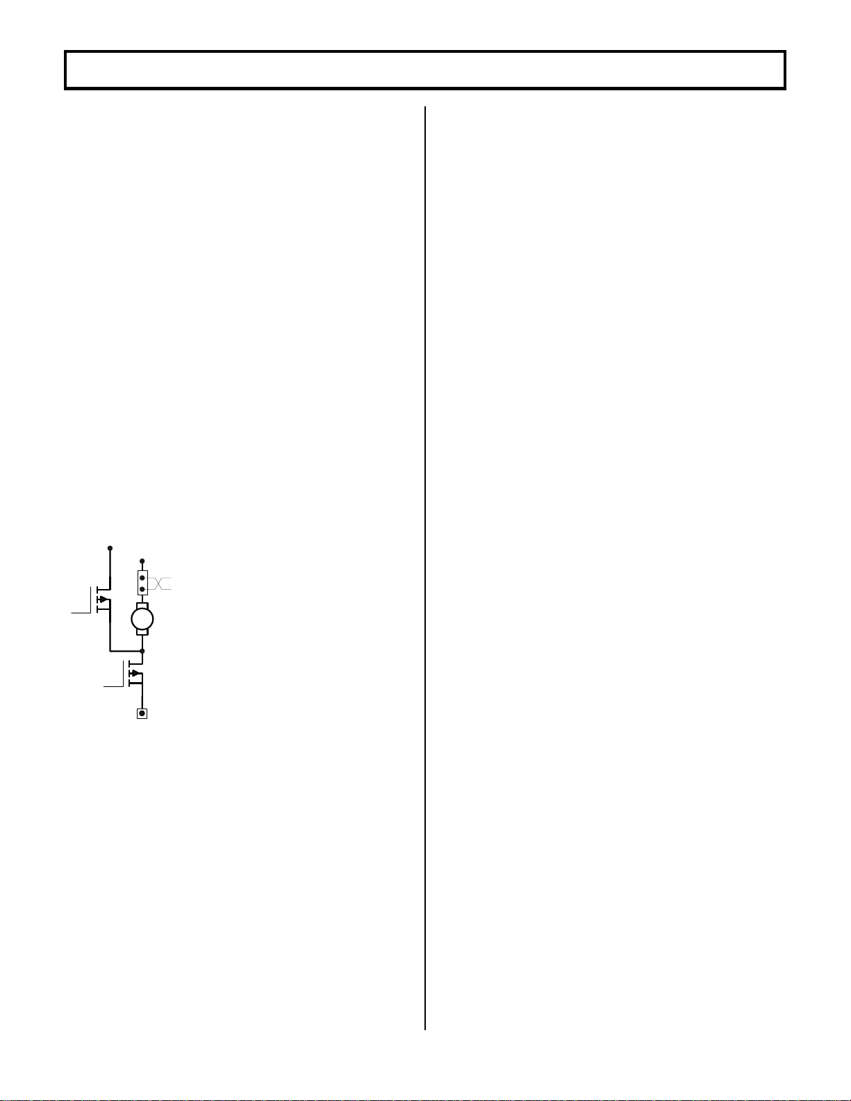
ARM
Q1
Q2