manuals.online logo
Brands
  1. Home
  2. •
  3. Brands
  4. •
  5. GE
  6. •
  7. Controllers
  8. •
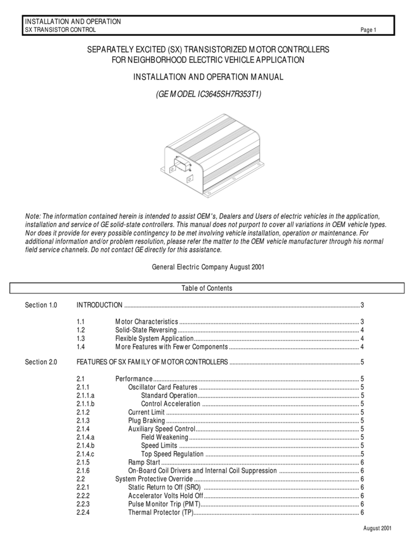
  9. GE 262E1 User manual

GE 262E1 User manual

49-Tomberlin Emerge (262E1_262TB1_403TB1) Install Sheet-370 Rev 02 11/29/18Sheet 1 of 4
CHECK MOTOR WINDINGS:
Set your VOM to RESISTANCE (Ω).
To test the resistance of VOM leads, please touch the meter leads together.
Subtract this measurement from each test below to get your true measurement.
With motor disconnected, measure A1 to A2. This should measure approximately BETWEEN .2Ω and 2Ω.
With motor disconnected, measure F1 to F2. This should measure approximately BETWEEN .8Ω and 3Ω.
With your motor disconnected, measure A1 to F1. This should measure OPEN.
With your motor disconnected, measure F1 to motor case. This should measure greater than 5MΩ.
CHECK MAIN SOLENOID:
Disconnect all wires from the main solenoid.
Set your VOM to RESISTANCE (Ω).
Measure the solenoid coil. This should measure 100Ω - 250Ω (depending on solenoid type).
Connect VOM leads to the main solenoid lugs.
Attach jumpers from main battery positive and negative to the coil (small terminals).
Meter must jump from infinity to LESS THAN .3Ω.
Remove jumpers and reconnect solenoid wiring from the harness. (If suppression diode is present,
The non-banded side must go to the wire from pin 11 (Pin 17 on 403E1/TB1) on the controller. Be sure to check diode
functionality with VOM prior to install. If pre-charge resister is installed, please remove. This control is equipped
with an internal resistor, and installing one on the solenoid could cause damage to the control)
CHECK THE CART WIRE HARNESS:
Check the connectors on the wire harness for corrosion, loose, broken, burnt or missing pins.
Repair or replace pins as necessary.
GE 262E1, 262/403 TB1 DIAGNOSTICS
STEPS TO PERFORM BEFORE CONTROL INSTALLATION
GE 262E1, 262TB1, 403E1, 403TB1
This sheet is provided to aid in the installation of your remanufactured General Electric
controller. Upon installation, you may encounter problems that may, or may not, be due to a
faulty controller. The following steps must be taken to help diagnose a possible cart fault or
faulty controller. An analog or digital volt ohm meter (VOM) will be needed to perform these
checks.
WARRANTY WILL BE VOID
If These Steps are Not Performed Before Installing The Control
IF ANY OF THE ABOVE ITEMS ARE NOT WITHIN THE SPECIFIED RANGES THE CONTROLLER WILL FAIL. THESE ITEMS MUST
BE CORRECTED BEFORE THE CONTROLLER IS INSTALLED OR WARRANTY WILL BE VOID.
It is recommended to replace your solenoid at the time of controller replacement. FSIP now stocks popular replacement White Rodgers solenoids for your convenience.
49-Tomberlin Emerge (262E1_262TB1_403TB1) Install Sheet-370 Rev 02 11/29/18Sheet 2 of 4
Diagram shows the back (wire) side of Connector
262E1, 262TB1,
403E1, 403TB1
Controller
FUSE
P1 (B+ from Run/Tow Switch)
For
P4 (Forward In)
Rev
P5 (Reverse In)
Reverse
Alarm
P10 (Backup Alarm Out)
Run/Tow
Switch
(Pot Wiper In) P7
Speed
Sensor
Out
+
-
(Speed Sensor Supply Out) P15
F1
48V Battery Pack
+
-
B-
B+
Main Solenoid
Contacts
F1
Motor
Field
F2
F2
(Speed Sensor In) P14
(Speed Sensor Return Out) P16
Main Solenoid Coil
P3 (Pedal Switch In)
Foot Pedal
P2 (B+ from Run/Tow Switch)
P11 (Main Solenoid Out)
P6 (Key Switch In)
PC/Run Switch
Key Switch
Sense
Circuit
E-Z-GO
ITS
PCB
Tomberlin Converter
PCB w/E-Z-GO ITS
Option #1 (Obsolete)
Option #2 (Current)
Sense
Circuit
TOMBERLIN ITS
B+
B-
B+
B-
OR
OR
0-5V
0-5V
Tomberlin p/n: 1007918 & 1008284
A
A1
Motor
Armature
A2
A2
A1
P17 (Main Solenoid Out) 403E1/TB1 model
49-Tomberlin Emerge (262E1_262TB1_403TB1) Install Sheet-370 Rev 02 11/29/18Sheet 3 of 4
Tomberlin Emerge Troubleshooting Sequence
FOR SAFETY, ALWAYS LIFT THE DRIVE WHEELS OFF THE GROUND WHEN TROUBLESHOOTING!
ALL TESTS ARE CONDUCTED WITH RUN-TOW/MAINTENANCE SWITCH IN THE RUN POSITION AND WITH A GOOD
BATTERY PACK VOLTAGE MEASUREMENT. ALSO, THE CONNECTOR MUST BE ATTACHED TO THE CONTROLLER
WHEN MAKING THESE CHECKS. YOU WILL NEED TO ‘BACK PROBE’ THE PINS FROM THE WIRE SIDE OF THE
CONNECTOR. USE A PAPERCLIP IF NECESSARY.
Attach voltmeter negative (-) lead to main Battery Negative (-) for the following tests.
Use the following sequence when checking individual pins (don’t skip steps). If you find a fault, do not move on
to the next step until the fault is corrected:
Measure the voltage at the main battery positive post (let’s call it Pack Voltage)
Pin 1 Must be equal to Pack Voltage
-If not Pack Voltage, check polarity protection diode, wiring, and Fuse for open condition
Pin 6 With Key Switch Off, must equal 0 volts
-If not 0 volts, check wiring and Key Switch for a shorted condition
Pin 6 With Key Switch On, must equal Pack Voltage
-If not Pack Voltage, check wiring and Key Switch for an open condition
Pin 2 With PC/Run Switch in Run mode, must equal Pack Voltage
-If not 0 volts, check wiring and Pc/Run Switch for an open condition
Pin 4 With F/R Switch in Reverse, must equal 0 volts
-If not 0 volts, check wiring and F/R Switch for a shorted condition
Pin 4 With F/R Switch in Forward, must equal Pack Voltage
-If not Pack Voltage, check wiring and F/R Switch for an open condition
Pin 5 With F/R Switch in Forward, must equal 0 volts
-If not 0 volts, check wiring and F/R Switch for a shorted condition
Pin 5 With F/R Switch in Reverse, must equal Pack Voltage
-If not Pack Voltage, check wiring and F/R Switch for an open condition
Pin 3 With Pedal Up, must equal 0 volts
-If not 0 volts, check wiring and Pedal Switch for a shorted condition
Pin 3 With Pedal Down, must equal Pack Voltage
-If not Pack Voltage, check wiring and Pedal Switch for an open condition
Pin 10 With Direction Switch in Neutral, must equal Pack Voltage
-If not Pack Voltage, check wiring and make sure beeper is present and connected
Pin 10 With Direction Switch in Reverse, must equal approximately 0 volts (and beeper sounds)
-If not approximately 0 volts, check connector and wire terminal for being burnt/corroded. If
terminal is clean, controller may be defective
Pin 7 With Pedal Up, must be less than .5 volts
-If not less than approximately .5 volts, check wiring and ITS assembly connections
Pin 7 With Pedal Fully Down, must equal approximately 5.0 volts
-If not approximately 5.0 volts, check wiring and ITS assembly connections
Continued on next page …
49-Tomberlin Emerge (262E1_262TB1_403TB1) Install Sheet-370 Rev 02 11/29/18Sheet 4 of 4
Pin 15 Must equal approximately 11.5 volts
-If not approximately 11.5 volts, remove speed sensor to see if voltage recovers to 11.5 volts. If it
does return to 11.5 volts, replace speed sensor, if it does not return to 11.5 volts, check wiring
Pin 16 Must equal approximately 0 volts
-If not approximately 0 volts, check terminal for being burnt/corroded. If terminal is clean,
controller may be defective.
Pin 14 While slowly turning the drive wheel, must toggle between 0 volts and approximately 4.5 volts
-If not toggling, check wiring and if necessary replace Speed Sensor and magnet
Pin 11 (Pin 17 on 403E1/TB1) With Pedal Up, must equal approximately pack voltage
-If not approximately pack voltage, check PC/Run Switch, solenoid coil and wiring for an open
condition
Pin 11 (Pin 17 on 403E1/TB1) With Pedal Down, must equal approximately 0 volts
-If not approximately 0 volts, check terminal for being burnt/corroded. If terminal is clean,
controller may be defective.
Upgrade Note: If upgrading from 262 to the 403, pin 11 will need to be moved to pin 17 location.
Helpful Hints
DO NOT UNDER ESTIMATE THE IMPORTANCE OF MOTOR RESISTANCE CHECKS AND MAIN SOLENOID CHECKS.
MANY CART ISSUES ARE CAUSED BY BURNT/DAMAGED BRUSHES THAT WILL BE FOUND AS PART OF THE
ARMATURE RESISTANCE CHECK. ALSO A SHORTED ARMATURE AND FIELD WITHIN THE MOTOR WILL DAMAGE
THIS CONTROLLER.
PRE-INSTALLATION
INSTRUCTIONS MUST BE
FOLLOWED OR WARRANTY
WILL BE VOID
IMPORTANT!
TOMBERLIN EMERGE
TROUBLESHOOTING INFORMATION
INCLUDED IN THIS PACKET
Flight Systems Industrial Products also offers the
following Technical Support options …
Troubleshooting Manuals / Codes
www.fsip.biz/TroubleshootingManuals.html
Live Tech Support Chat
www.fsip.biz
Technical Support Forum
fsip.websitetoolbox.com
Frequently Asked Questions
www.fsip.biz/FAQ.html
Phone Support
1-800-333-1194 (Option 4)

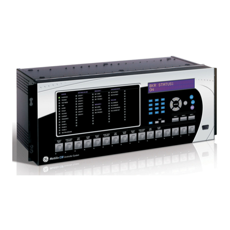
This manual suits for next models

3

Other GE Controllers manuals

GE ASTAT XB User manual

GE

GE ASTAT XB User manual

GE Multilin GEK-113000T User manual

GE

GE Multilin GEK-113000T User manual

GE Becker VRP-SB-PID Series User manual

GE

GE Becker VRP-SB-PID Series User manual

GE PACSystems* RX3i User manual

GE

GE PACSystems* RX3i User manual

GE IC3645SR3R404P2 User manual

GE

GE IC3645SR3R404P2 User manual

GE IC3645SR7A353E1 User manual

GE

GE IC3645SR7A353E1 User manual

GE ASTAT XT QT 0008U Series User manual

GE

GE ASTAT XT QT 0008U Series User manual

GE DMC490 User manual

GE

GE DMC490 User manual

GE C30 User manual

GE

GE C30 User manual

GE T60 User manual

GE

GE T60 User manual

GE RSTi-EP User manual

GE

GE RSTi-EP User manual

GE AF-650 GP Series User manual

GE

GE AF-650 GP Series User manual

GE Masoneilan 4700E User manual

GE

GE Masoneilan 4700E User manual

GE IC3645SH7R354D2 User manual

GE

GE IC3645SH7R354D2 User manual

GE IC3645SR4R404U2 User manual

GE

GE IC3645SR4R404U2 User manual

GE VAT20 User manual

GE

GE VAT20 User manual

GE IC3645SH7R353E2 Owner's manual

GE

GE IC3645SH7R353E2 Owner's manual

GE GuardSwitch 300 Series User manual

GE

GE GuardSwitch 300 Series User manual

GE Mooney Flowgrid User manual

GE

GE Mooney Flowgrid User manual

GE IC3645SR7A353T4 User manual

GE

GE IC3645SR7A353T4 User manual

GE GPS2BHA User manual

GE

GE GPS2BHA User manual

GE PMC423 Series Application guide

GE

GE PMC423 Series Application guide

GE RX3i PROFINET User manual

GE

GE RX3i PROFINET User manual

GE IC695CNM001 User manual

GE

GE IC695CNM001 User manual

Popular Controllers manuals by other brands

Steren MODLED-010 instruction manual

Steren

Steren MODLED-010 instruction manual

Herz clever&smart Room Controller Installation and operating instruction

Herz

Herz clever&smart Room Controller Installation and operating instruction

FUJIDENZO FVR-2000SC Operation manual

FUJIDENZO

FUJIDENZO FVR-2000SC Operation manual

Kelly KLS6045H user manual

Kelly

Kelly KLS6045H user manual

Moeller Home-Manager operating instructions

Moeller

Moeller Home-Manager operating instructions

Yaesu G-550 instruction manual

Yaesu

Yaesu G-550 instruction manual

Omron NJ-series Network Connection Guide

Omron

Omron NJ-series Network Connection Guide

Infineon XDPP1100 user manual

Infineon

Infineon XDPP1100 user manual

Lumen WF-C user manual

Lumen

Lumen WF-C user manual

Johnson Controls CVM03050 installation guide

Johnson Controls

Johnson Controls CVM03050 installation guide

J&E Hall Fridgewatch 4000 Installation, operating and maintenance manual

J&E Hall

J&E Hall Fridgewatch 4000 Installation, operating and maintenance manual

BIFFI ALGA - EAC Installation, operation and maintenance manual

BIFFI

BIFFI ALGA - EAC Installation, operation and maintenance manual

FW Murphy Centurion C5 M-VIEW Touch Series Operation manual

FW Murphy

FW Murphy Centurion C5 M-VIEW Touch Series Operation manual

Moore Industries 532 user manual

Moore Industries

Moore Industries 532 user manual

Arcadia REPTILE CONTROLLER RACRE Installation and maintenance instructions

Arcadia

Arcadia REPTILE CONTROLLER RACRE Installation and maintenance instructions

Centurion D3 quick guide

Centurion

Centurion D3 quick guide

Leviosa Zone user manual

Leviosa

Leviosa Zone user manual

Walchem WCU Series instruction manual

Walchem

Walchem WCU Series instruction manual

manuals.online logo
manuals.online logoBrands
  • About & Mission
  • Contact us
  • Privacy Policy
  • Terms and Conditions

Copyright 2025 Manuals.Online. All Rights Reserved.